OCEM PAPI User manual

Use and Maintenance Manual
ocem
EN
29acdb84-d07b-41e6-b3b5-3049609cfc5f
HALO
Precision
Approach
Path
Indicator
FIXTURE FOR
AIRPORTS-HELIPORTS
HALOGEN LAMPS
LOW MANAGEMENT COSTS
LOW MAINTENANCE
UT-MT-0970_1.0_02-08-2022 (EN)

Contact us
Editions
Revision Date Notes
1.0 02-08-2022 First edition

UT-MT-0970_1.0_02-08-2022 (EN)
Use and Maintenance Manual
PAPI
3
1 GENERAL INFORMATION
1.1 Package content 5
1.2 Manual reference guide 6
1.3 Safety instructions 6
1.4 Safety symbols 7
1.5 Denitionofoperator 7
1.6 Limited warranty 8
1.7 CE marking 9
1.8 Condentiality,industrialpropertyrights 9
1.9 Disposal 9
1.10 Articleidentication 9
1.11 Photo-biologicalrisk 10
2 FIXTURE DESCRIPTION
2.1 Generalcharacteristics 11
2.2 Article number 15
2.3 Wiring 16
2.4 Methodofcalculationoftheinstallationparameter 16
3 INSTALLATION
3.1 Fixtureplacement 19
3.2 Foot assembly 20
3.3 Unitpermanentinstallation 21
3.4 Initialinspection 24
4 ADJUSTMENTS AND MAINTENANCE
4.1 Scheduledmaintenance 25
4.2 Removalofthecover 26
4.3 Cleaningthefrontglass 27
4.4 Replacementofthelamp 28
4.5 Replacementofthesupport 30
4.6 Troubleshooting 33
4.7 Spareparts 35

Page intentionally left blank
UT-MT-0970_1.0_02-08-2022 (EN)
Use and Maintenance Manual
PAPI
4

GENERAL INFORMATION
UT-MT-0970_1.0_02-08-2022 (EN)
Use and Maintenance Manual
PAPI
5
ThePAPIofOCEMAireldTechnologyisanelevatedsignallingsystemPAPItypetoindicatetoapproaching
aircraftstheverticalpositionwithrespecttotheoptimalvalue.Thedeviceisdesignedincompliancewith:
●ICAOAnnex14-VolumeI(Paragraph5.3.5)andAerodromeDesignManual(Part4):PrecisionApproach
Pathindicator(PAPI)andAbbreviatedPAPI(A-PAPI);
●CASA:ManualofStandardsPart139;
●NATO:Stanag3316;
●ENAC(ItalianCivilAviationAuthority):ENACAirportConstructionRegulation.
Immediatelycheckforvisibledamagesofthecontainer.Carefullyremovethedeviceandcheckforvisibledamages.
Check the presence of all accessories that can be ordered separately (EMT 2” pipe) and any assembly tool
(optionals).Beforeproceedingreadallwarningsonthepackaging.
Store all the components in the original packaging until the time of installation.
Pay attention not to damage the cables, the pipes or the watertightness of the components.
The device described in this manual has been designed to be powered by series circuits,
powered by constant current regulators from 6,6 A.
1 GENERAL INFORMATION
1.1 Package content

GENERAL INFORMATION
UT-MT-0970_1.0_02-08-2022 (EN)
Use and Maintenance Manual
PAPI
6
1.2 Manual reference guide
Thisdocumentcontainsalltheinformationrelatedtotheequipmentanddescribestheprocedurestofollowduring
theinstallationoftheproductandduringordinarymaintenance.Thedocumentisindentedforalloperatorsthat
mustinterveneontheequipment.
This document does not replace in any manner applicable laws, rules or regulations, included the
standards FAA and ICAO.
Theprecautionsprovidedinthemanualarealwaysprecededbyasymbolasillustratedbelow:
Indicates the warnings, the notes, the suggestions and other points on which is intended to
draw the attention of the reader.
Indicates the operations to be carried out mandatorily or the information which should be
carefully read to avoid possible risks.
Indicates particular risks connected with the power supply. It reports the operations to be
carried out mandatorily or the information which should be carefully read to avoid possible
risks.
Theseprecautionssafeguardthepersonalsecurityofeveryonewhoworkonand/orareinproximityoftheequipment
andoftherelativesupplycircuits.
The failure to comply with the instructions (in particular those preceded by danger, warning, caution
precautions) can cause serious injury or death.
1.3 Safety instructions
CAREFULLY READ THIS DOCUMENT.
The improper use of the equipment or the failure to comply all the precautions indicated
implies life danger and serious injury to persons and damages to things.
HAZARD OF ELECTRICAL SHOCK, EXPLOSION OR ELECTRIC ARC
Carefully read the enclosed documentation before installing or starting to use the equipment.
Do not install the equipment until the completion of all construction works required to carry
out the work.
DO NOT OPERATE ON POWERED CIRCUITS
Do not carry out any operation on powered circuits.
Beforeeveryaccess,inspectionorinterventionontheequipment,ensuretohaveswitchedothe
equipmentbyopeningthemainpowerswitchandbyremovingthesupplyfromtheunit(openthe
powerswitchatthebeginningofthelineorswitchotheconstantcurrentregulator).
The failure to comply all the precautions indicated implies life danger and serious injury to
persons.

GENERAL INFORMATION
UT-MT-0970_1.0_02-08-2022 (EN)
Use and Maintenance Manual
PAPI
7
1.4 Safety symbols
Thesymbolsillustratedinthefollowingtableareusedintheuserandmaintenancemanualandonthedevice.
Thesesymbolsindicatetheexistenceofanydangeroussituations,toindicateobligationsandprohibitionsinrelation
tothesituationsthatmayrepresentanhazardfortheoperatororindicatethebehaviourtoadopttominimizethe
riskfortheoperator.
Warning signs Prohibition and obligation signs
W001 | General warning sign P001|Generalprohibitionsign
W004 | Laser beam M001 | General mandatory sign
W005|Non-ionizingradiation M002 | Refer to instruction manual/
booklet
W006|Magneticeld M005|Connectanearthterminaltothe
ground
W012 | Electricity M009|Wearprotectivegloves
W017 | Hot surface M015|Wearhighvisibilityclothing
W027|Opticalradiation M021 | Disconnect before carrying out
maintenanceorrepair
1.5 Denition of operator
Alloperationsondevicesandonitsinternalpartsmustbeperformedbyprofessionalsta,properlyformedand
awareoftherisksconnectedwiththepowersupplyandtotheuseoflowandhighvoltagecircuits.
Take all the precautions in compliance with the safety standards for the work carried out on
electrical installations and however for the works carried out using electrical installations or
in buer zones of the installations and of the electrical devices.
Alloperationsonequipmentsandonitsinternalpartsmustbeperformedbyprofessionalsta,properlytrained
forCardioPulmonaryResuscitation(CPR)techniques.
Never operate on devices if there is not at least another operator properly trained for CPR
techniques.
CheckthatOperatorsdonotoperateoutsidetheirownspeciceldsofcompetenceandresponsibility.OCEM
AireldTechnologydeclinesanyandallliabilityarisingfromwrongoperationscarriedoutbyuntrainedpersonnel
intheuseofthedevices,orderivingfromthenoncomplianceofgeneralsafetystandards.

GENERAL INFORMATION
UT-MT-0970_1.0_02-08-2022 (EN)
Use and Maintenance Manual
PAPI
8
1.6 Limited warranty
OCEMAireldTechnologyassuresthatallthePAPIproductsmarketedarefreeofmanufacturingdefectsatthe
timeofshipment.Thislimitedwarrantywillbevalidfortheperiodindicatedinthesalesagreement.THISLIMITED
WARRANTYIMMEDIATELYDECAYSIFTHEPRODUCTISUSEDFORPURPOSESOTHERTHANORIGINALLY
INTENDED.
ThislimitedwarrantyisprovidedbyOCEMAireldTechnologytotheoriginalpurchaserofPAPIproductsasidentiedbythe
documentsissuedatthetimeofpurchase.ThislimitedwarrantycanbetransferredtothesubsequentpurchasersoftheProduct,
onlyonconditionthatthisProductisresoldasNEWandwiththeoriginalpackaging.
Each change and/or tampering made to the product immediately terminates the warranty. OCEM
Aireld Technology cannot be held responsible for any damage to items or persons deriving
from the failure to comply with instructions relating to installation, use and maintenance of
the product, and to the installation and storage environmental conditions stipulated by the
Manufacturer or by applicable rules regarding electrical devices and systems.
Incaseofpotentialdefectsornon-usabilityoftheGoodssupplied,theapplicablewarrantythatexcludesanyotherlegalwarranty
andagreement-appliestothedefectsofmaterials,inthedesign,and/orintheinstallationoftheGoodssupplied.Thewarranty
consists,dependingontheSupplier,intherepairorreplacement,attheexpenseoftheSupplier,ofeachfaultycomponentor
malfunctioningcomponentfromthebeginning,butisnotextendedtodamagesarisingfromnegligenceorwear.
Thiswarrantylastsforatleast12monthsafterthedateonwhichthereceivedGoodsareputintoservice,butwillnotinany
caseexceed24monthsfromtheshippingdate.
FAA
For FAA certied products this warranty lasts for at least 4 years after the date on which
the received Goods are put into service, but will not in any case exceed 5 years from the
shipping date.
TheSupplierundertakestorepairorreplacethecomponentsintheshortestpossibletimewithoutprejudicetothefactthatfor
thesocalledcommercialcomponentsandmoregenerallyforthecomponentssuppliedbythird-partymanufacturers,willonly
beappliedthetermsoftherespectiveoriginalmanufacturer'swarranties.
ThewarrantyabsolvesfromallliabilitytheSupplieranddoesnotapplytothedamageofanykind,causedby:improperuse
bytheCustomerorbytheCustomer’ssta,useofinadequatematerials,orincorrectorinsucienttreatments;installation
ofequipmentsorsparepartsnotapprovedbytheSupplier;installationandoperatingworkingoftheGoodsreceivedwithout
followingtheindicationsandtheinstructionsprovidedbytheSupplier’sTechnicalsta;improperorexcessiveuse,insucient
maintenance,and/orworksnotcarriedoutincompliancewiththeinformationprovidedintheuseandmaintenanceinstructions;
anyotherreasonnotattributabletotheSupplier.TheCustomermustshoulder,atitsowncostandemployingitsownsta,
withoutinvolvingtheSupplier,thoserepairsthatonthebaseoftheSupplier’sopinionareconsideredcompliantatamoderate
leveloftechnicalknow-how.
TheCustomermust,underpenaltyofexpiration,communicatethecomplaintconcerningthedefectorthenon-compliancetothe
Supplierwithin 8 days from the date of discovery of the defect,andmustsendawrittenrequesttoactivatetheintervention
underwarranty.Theinterventionrequestunderwarrantymustbesentto:
OCEM Aireld Technology | via della Solidarietà, 2/1 | 40056 Valsamoggia BO (Italia)
TheCustomermustbearthetravelandaccommodationcostsbornebythetechnicalstaoftheSupplierthatmust
completeontheinstallationsiteanyinterventionassociatedwiththeguarantee.
Thewarrantyexcludesanyotherdamage,includedthoseresultingfromeconomiclossandfromlowproduction
capacity;direct,indirectorconsequentialdamages;andtheContracttermination.
TheSupplierisnotinanymannerresponsibleforanyothercompensationorindemnity,includingdamagederived
frommissedorreducedproduction,fromthelossofchance,fromthemissedorreducedprot,fromthelossof
contracts,impossibilityofuseoringeneralthepartialuse,inadditiontoindirectand/orconsequentialdamages.
GENERAL INFORMATION
UT-MT-0970_1.0_02-08-2022 (EN)
Use and Maintenance Manual
PAPI
9
1.7 CE marking
ThisequipmentcomplieswiththerequirementsofEuropeanlegislationfortheCEmarking.The
usershouldcarefullyreadthisdocumentandrespectalltherequirementsquoted.
ThisequipmentmeettherequirementsinrelationtohealthandsafetyofthemainECdirectives,andinparticular
oftheEMCDirectiveonelectromagneticcompatibility(2014/30/EU)andoftheLVDirectiverelatingtoelectrical
equipmentdesignedforusewithincertainvoltagelimits(2014/35/EU).
1.8 Condentiality, industrial property rights
TheCustomerneedstoadoptthemaximumcondentialitywithrespecttoalltheinformationoftechnicalnature
(including,bywayofexampleandnotexhaustively,plans,programmes,documentation,formulas,recipes,setting
andcorrespondence)receivedbytheSupplierorinanycaseassimilatedorgainedduringtheconclusionofthe
Contract of sale.
Anyrightregardingintellectualandindustrialpropertyconnectedtoequipmentandtoanyotherelementincluded
inthesuppliedGoodsasindicatedintheContractremainexclusivepropertyoftheSupplier.
1.9 Disposal
Attheendofuse,theusermustconferallthewasteinsuitabledierentiatedwastecollectioncentres.
ItistheresponsibilityoftheuserthecorrectdisposaloftheequipmentinaccordancewiththeWEEE
Directiveandwiththerespectivenationallawsinforceatthetimeofdisposal.Theseequipments
mustneverbedisposedofinthehouseholdwaste.
1.10 Article identication
Oneachequipmentthereisanidenticationplateofthearticle,wherethearticlecodeisreported;ontheplate
thereareadditionaldata:thenameofthemodel,employmentsoruse,powersupplyfeatures,anytrademarks
and/ormarksthatattesttheagreementoftheequipmenttospecicregulationsorlegislations.

GENERAL INFORMATION
UT-MT-0970_1.0_02-08-2022 (EN)
Use and Maintenance Manual
PAPI
10
1.11 Photo-biological risk
ThexturesPAPIaredesignedandmanufacturedincompliancewithcurrentregulations,butifusedunsafelyor
withoutprecautions,thelightemittedbythexture,reachingevenhighlevelsofintensity,canbeharmfulnotonly
tothosewhousethelightxturelocally,butforanyonewithinthelightbeamrange.
Theopticalradiationissuedbytheequipmentdoesnotpresentanyparticularphoto-biologicalrisks,howevercan
beharmful.
Don’t look directly inside the light source during high intensity operation. Wear appropriate
personal protective equipment (goggles or similar protections).

Description
UT-MT-0970_1.0_02-08-2022(EN)
Use and Maintenance Manual
PAPI
11
Thextures,positionedontheleftofthelandingarea,projectstablelightbeamsanddependingontheapproach
angletherecanbedierentcombinations:
PAPI Glideslope A-PAPI Glideslope
● ● ● ● Veryhighglideslope ● ● Highglideslope
● ● ● ● Slightlyhighglideslope
● ● ● ● Appropriate approach glideslope ● ● Appropriate approach glideslope
● ● ● ● Slightlylowglideslope ● ● Lowglideslope
● ● ● ● Verylowglideslope
2 FIXTURE DESCRIPTION
2.1 General characteristics
ThePAPIxturesaredesignedforthepurposeofprovidingvisualguidancetoaircraftsinthebichromaticapproach
ashsignalling:
●Four-lightPAPI:thesystem(inuseincommercialandmilitaryairports)consistsof4unitseachequipped
with2or3lamps(200W),current-poweredinenvironmentswithtemperaturesbetween-55°C[-67F]and
+55°C[+131F].
●Two-lightPAPI:thesystem(inuseincommercialairportsorheliports)consistsof2unitseachequipped
with2lamps(100or200W),current-poweredinenvironmentswithtemperaturesbetween-55°C[-67F]
and+55°C[+131F].
Thehalogenlampsinstalledallowtominimizemaintenancecosts.Optics,madeupofanaluminiumparabolic
reector,alterandalensassureuniformintensityandthered/whiterapidtransitiontoprovidethepilotwithan
accuratereportingontheglideslopeapproachingtherunway.ThePAPIxtureisadeviceabletooerinthesame
opticsvisibleandinfraredoperatingstates.

Description
UT-MT-0970_1.0_02-08-2022 (EN)
Use and Maintenance Manual
PAPI
12
SUPPORT
Semi-sphericaljoint
Threadedpin
Locking ring nut
Baseplate
Frangiblecoupling
PoleEMT2”
supplied separately - to be
cut to the desired length
PAPI401C/H(2lampsversion)
PAPI401C/M(3lampsversion)
Availablewithsupportsforxedinstallationwithcontrolledfrangiblecoupling,thePAPIsystemisdesignedtobe
installedonconcretebasesproperlydimensioned.
ThePAPIiscompliantwiththerules:
ICAOAnnex14-VolumeI(Paragraph5.3.5)andAerodrome
DesignManual(Part4)
CASA Manual of Standards Part 139
NATO Stanag 3316 ENACAirportConstructionRegulation
The xtures PAPI described in this manual have been designed to be installed on the concrete
basis of suitable dimension.
The threaded fastening system must be installed in the right position.
The supply circuits for the light(s) xtures (one for each lamp) can be positioned within plastic
or metallic pipes permanently laid in the ground, equipped with appropriate coupling devices.

Description
UT-MT-0970_1.0_02-08-2022(EN)
Use and Maintenance Manual
PAPI
13
DT: Theoreticalthreshold-Distanceoftheopticalaxis
DY: Distancebetweenthecentreofthelandingrunway/
helipadandlongitudinalaxisoftheunit
α: Elevation angle of the unit (compared with the
threshold)
DA: DistanceofthepointA(infrontoftheunit)
QA: ElevationmeasurementofthepointA
DB: DistanceofthepointB(behindtheunit)
QB: ElevationmeasurementofthepointB
DO: Actualthreshold-Distanceoftheopticalaxis
DX: Actualthreshold-Distanceofthefrontsupport
QO: Actualelevationoftheopticalaxis
QOC:Conventionalactualelevationoftheopticalaxis
QC: Actualelevationofthebase
TheexampleshowsthemainmeasurestobeevaluatedforproperdesignofthePAPI(orA-PAPI)system:
TheinstallationofaPAPI(orA-PAPI)systemrequiresspecicdesigncorrectlyassessingthepositioning,orientation
andinclinationofdevicesaccordingtothecharacteristicsofaireld-helipad:
●Conformationofthelandingrunwayorofthehelipad;
●Theelevationoftheinstallationpoints(comparedwiththethresholdortothecentreoftheplatformTLOF);
●Theapproachangle;
●Theminimumheightofthelineofsightofthepilotabovethethresholdorthehelipad.
IfastructureisequippedwithInstrumentLandingSystem(ILS),itmustbetakenintoconsiderationalsothedistance
betweentheoriginoftheglidepathandthethreshold.

Description
UT-MT-0970_1.0_02-08-2022 (EN)
Use and Maintenance Manual
PAPI
14
Theconcretebasemustrespectalltheindicationsfortheirproperimplementation.
FortheproperinstallationofthePAPIsystem(optional)equipmentsareavailableforinstallation,pointingand
xturesadjustment:atemplate(1)forthepositioningofthegroundanchorage(diversiedforthe2or3lamps
model),thethreadedanchorageanges(2)(2”11-GAS),alinear levelgauge(3)forthexturealignment,an
analogueclinometer(4)withrelatedsupportbrackettoadjusttheunits.Forfurtherinformationontheuseofthe
mountingaccessories,pleaserefertotherespectivemanuals.

Description
UT-MT-0970_1.0_02-08-2022(EN)
Use and Maintenance Manual
PAPI
15
2.2 Article number
example: 401CP - 2 - 20 - 18-16
Standard
C
M
H
=
=
=
ICAO/CASA
NATO*
Heliport(ICAO)**
System
P
A
U
=
=
=
PAPIsystem(4units)
A-PAPIsystem(2units)
Single unit
Number of lamps
2
3
=
=
Twolampsunit
Threelampsunit
Type of installed lamp
10
20
=
=
100W6.6APK30/d+
200W6.6APK30/d
Option
16
18
ANT
=
=
=
Frontglass(alwayspresent)
Flexiblesheathingforpowercableprotection
Anti-condensationheater
* NATOsystemcongurableonlywith3lampsunit
** Heliportsystem(ICAO)congurableonlywith2lampsunit
+Lamp 100 W available only for PAPI systems for Heliport
Intheexample401CP - 2 - 20 - 18-16:4lightunitsPAPIsystemforairportscompliantwithICAOstandard.2200W
lampsxtures(6.6APK30/d),equippedwithprotectivefrontglassandadaptablesupportsystem(note:PoleEMT
2”notprovided,tobeorderedseparately).Systemequippedwithexiblesheathingsforpowercableprotection.

Description
UT-MT-0970_1.0_02-08-2022 (EN)
Use and Maintenance Manual
PAPI
16
2.4 Method of calculation of the installation parameter
ToproperlyinstallthePAPI401systemthefollowingparametersmustbeassessed:
●DX: actualdistanceofthefrontleginrelationtothethreshold
●QC: elevationoftheconcreteplatforminrelationtothethreshold
2.3 Wiring
ThePAPI401systemmustbepoweredbyacircuitairportseries(6.6A).
In case of double PAPI system, installed both right and left of the landing runway (or of the
helipad), each branch should be powered by a dierent series circuit. Thus congured, the
failure of a power supply circuit causes the failure to function on only one of the two blocks.
In case of single PAPI system, installed only on the right and on the left of the landing runway
(or in front of the helipad), is appropriate to use a single circuit to power the unit.
Using two dierent circuits to power the lamps of a single unit, the fault of a circuit can
generate a misreading of the xture inducing the pilot into error.

Description
UT-MT-0970_1.0_02-08-2022(EN)
Use and Maintenance Manual
PAPI
17
ThetheoreticaldistanceDTbetweentheopticalaxisoftheunitorthecentreoftheTLOFplatformcanbecalculated
withthefollowingformula:
wheretheMangleisequivalenttotheapproachangleminus2minutesofarc.Theapproachangledependson
theinstallationtype:
●Aireld: (anglereferredtothesecondunitonthesideoftherunway)
●AireldwithILSsystem(InstrumentLandingSystem): (anglereferredtothesecond
unitonthesideoftherunway)
●AireldwithMLSsystem(MicrowaveLandingSystem): (anglereferredtothesecond
unitonthesideoftherunway)
●Helipad: (angle referred to the left side, from the point of view of the pilot
approaching)
TheactualdistanceoftheopticalaxisDOoftheunitinrelationtothethresholdcanbecalculatedwiththefollowing
formula(distancesexpressedinm):
TheactualelevationoftheopticalaxisQOCinrelationtothethresholdortotheaxisoftheplatformTLOFcanbe
calculatedwiththefollowingformula(distancesexpressedinm):
For more information on the meaning of the symbols, please refer to the previous paragraphs.
AftercompletionofthevalueoftheactualdistanceDOandoftheactualelevationDOCispossibletoobtainthe
valueoftheparametersrequiredforcivilworks.
TheactualdistanceofthefrontlegDX inrelationtothethresholdortotheaxisoftheplatformTLOFcanbecalculated
withthefollowingformula(distancesexpressedinm):
TheelevationoftheconcreteplatformCX inrelationtothethresholdcanbecalculatedwiththefollowingformula
(distancesexpressedinm):

Page intentionally left blank
UT-MT-0970_1.0_02-08-2022 (EN)
Use and Maintenance Manual
PAPI
18

INSTALLATION
UT-MT-0970_1.0_02-08-2022 (EN)
Use and Maintenance Manual
PAPI
19
3 INSTALLATION
3.1 Fixture placement
Thesignallingdevices,incombinationwithhorizontalandverticalxtures,provideinformationtothepilotsand
thereforerepresentafundamentaldrivingaid.
Thesedevicesmustalwaysbeinoperatingconditionandmustbeclean,maintainedand,ifnecessary,replaced
assoonastheirvisibilityisaected.
Thelightsourcesmustbepositionedaccordingtothelegislativeprovisionsneartherunwayorientedtowardsthe
approachdirectiontothelandingrunway.Theopticalaxisoftheunitmustbeparalleltotherunwayedge.The
positioningofthelightunitsoftherunwaymustbeincompliancewithcurrentregulations.
For the positioning of the xtures always refer to the requirements of the relevant Standards:
• ICAO Annex 14 Part 1 5.3.5 - PAPI and APAPI

INSTALLATION
UT-MT-0970_1.0_02-08-2022 (EN)
Use and Maintenance Manual
PAPI
20
3.2 Foot assembly
Store all the components in the original packaging until the time of installation.
Screwtheringnuttothefrangiblecouplingforabout2threadturns.Screwthecouplingontheplateuntiltightening.
Inserttheringinsidetheseatandscrewthenutonthefrangiblecouplingwithouttightening(makemaximum3turns).
Inserttheringinsidetheseatandscrewthenutonthethreadedpinwithouttightening(makemaximum3turns).
CuttheEMT2”pipetothelengthenvisagedintheproject.Insertthetubeinthejointandtightenthenut.
Positionthethreadedpinandtightenthenut.
Table of contents
Other OCEM Lighting Equipment manuals

OCEM
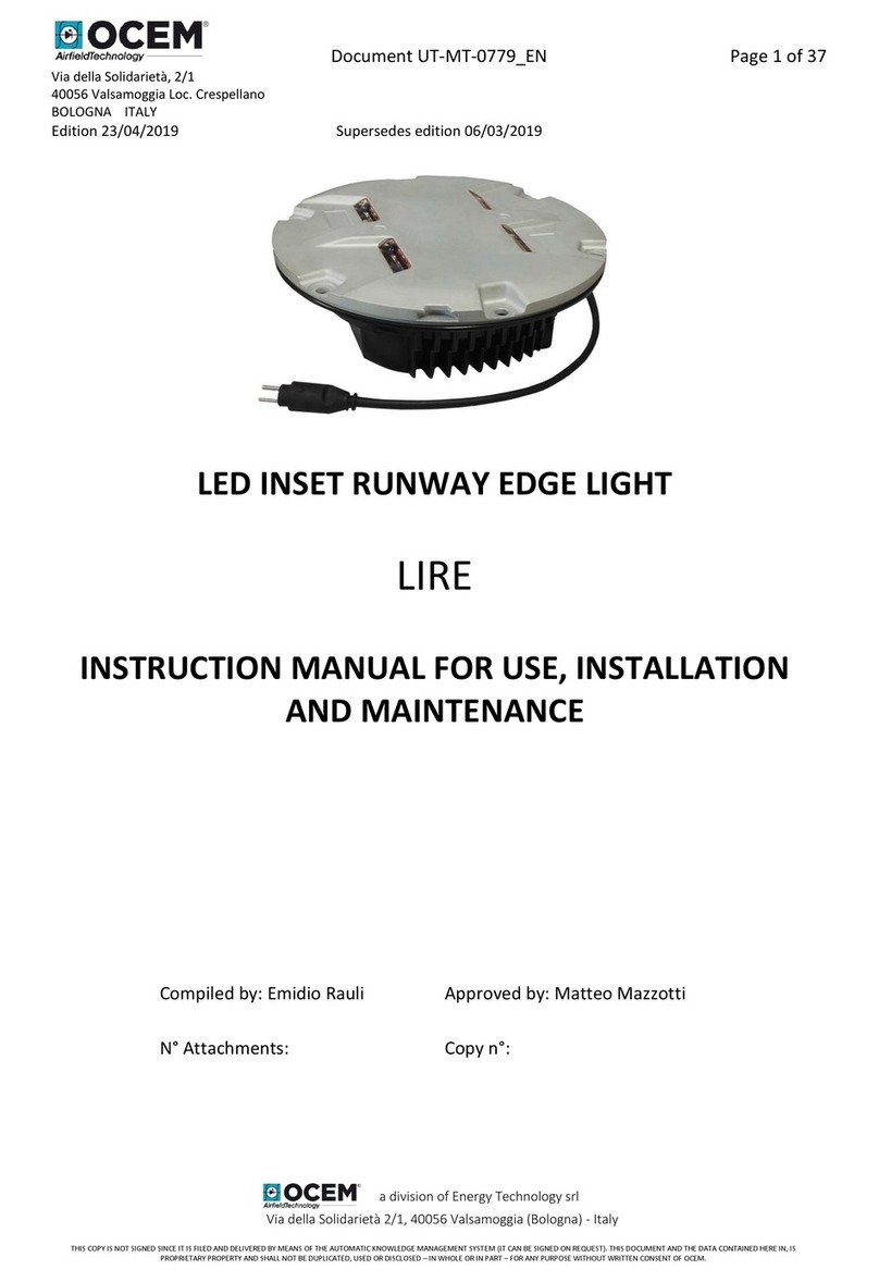
OCEM LIRE Series Instruction manual

OCEM
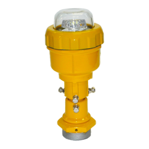
OCEM LIMS Instruction manual

OCEM
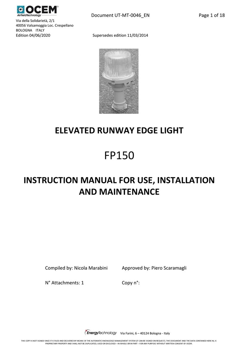
OCEM FP150 Instruction manual

OCEM
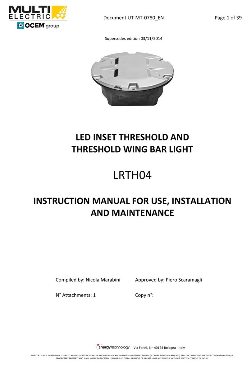
OCEM Multi Electric LRTH04 Instruction manual

OCEM
OCEM MULTI ELECTRIC LETG User manual

OCEM
OCEM MULTI ELECTRIC LTHE04 Instruction manual

OCEM
OCEM LSDS Instruction manual

OCEM
OCEM LERA P-001 User manual

OCEM
OCEM SLTH Instruction manual

OCEM
OCEM LHE Instruction manual
Popular Lighting Equipment manuals by other brands

Chauvet
Chauvet SlimPAR T6 USB user manual

Sagitter
Sagitter SG ACLPAR1 user manual

Heitronic
Heitronic 30390 Installation and operating instructions

APEXEL
APEXEL APL-FL10JJ14 user manual

Knightsbridge
Knightsbridge TRLED 1 Series Installation & maintenance manual

lighting PLUS
lighting PLUS IP-1940B user manual