OCEM Multi Electric LRTH04 Instruction manual

Document UT-MT-0780_EN Page 1 of 39
Supe sedes edition 03/11/2014
Via Fa ini, 6 – 40124 Bologna - Italy
THIS COPY IS NOT SIGNED SINCE IT IS FILED AND DELIVERED BY MEANS OF THE AUTOMATIC KNOWLEDGE MANAGEMENT SYSTEM (IT CAN BE SIGNED ON REQUEST). THIS DOCUMENT AND THE DATA CONTAINED HERE IN, IS
PROPRIETARY PROPERTY AND SHALL NOT BE DUPLICATED, USED OR DISCLOSED – IN WHOLE OR IN PART – FOR ANY PURPOSE WITHOUT WRITTEN CONSENT OF OCEM.
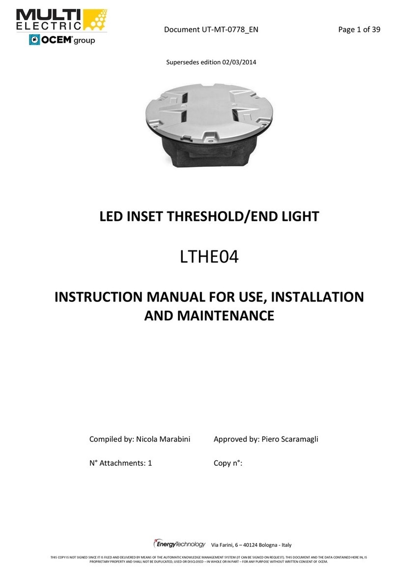
LED INSET THRESHOLD AND
THRESHOLD WING BAR LIGHT
LRTH04
INSTRUCTION MANUAL FOR USE, INSTALLATION
AND MAINTENANCE
Compiled by: Nicola Ma abini App oved by: Pie o Sca amagli
N° Attachments: 1 Copy n°:
MULTI
ELECTRIC
group

Document UT-MT-0780_EN Page 2 of 39
Edition 03/10/2015 Supe sedes edition 03/11/2014
LED INSET THRESHOLD AND THRESHOLD WING BAR LIGHT LRTH04
INSTRUCTION MANUAL FOR USE, INSTALLATION AND MAINTENANCE
LIMITED PRODUCT WARRANTY
THE FOLLOWING WARRANTY IS EXCLUSIVE AND IN LIEU OF ALL OTHER WARRANTIES, WHETHER EXPRESS,
IMPLIED OR STATUTORY, INCLUDING, BUT NOT BY WAY OF LIMITATION, ANY WARRANTY OF
MERCHANTABILITY OR FITNESS FOR ANY PARTICULAR PURPOSE.
OCEM - ENERGY TECHNOLOGY wa ants to each o iginal Buye of P oducts manufactu ed by the Company
that such P oducts a e at the time of delive y to the Buye , f ee of mate ial and wo kmanship defects,
p ovided that no wa anty is made with espect to:
(a) any P oduct, which has been epai ed o alte ed in such a way, in Company’s judgement, as to affect
the P oduct adve sely;
(b) any P oduct which has, in Company’s judgement, been subject to negligence, accident o imp ope
sto age;
(c) any P oduct which has not been ope ated and maintained in acco dance with no mal p actice and in
confo mity with ecommendations and published specification of Company;
(d) the b eaking of the wa anty seals, if p esent, dete mines the immediate te mination of the wa anty;
and,
OCEM - ENERGY TECHNOLOGY’s obligation unde this wa anty is limited to use easonable effo ts to
epai o , at its option, eplace, du ing no mal wo king hou s at the facility of the Company, any P oduct
which in its judgement p oved not to be as wa anted within the applicable wa anty pe iod. All costs of
t anspo tation of P oducts claimed not to be wa anted and of those epai ed o eplaced, to o f om the
facility of the Company shall be bo ne by Pu chase . Company may equi e the etu n of any P oduct
claimed not to be as wa anted to its facility, t anspo tation p epaid by Pu chase , to establish a claim
unde this wa anty. The cost of labou fo the installation of a epai ed o eplaced P oduct shall be
bo ne by Pu chase . Replacement pa ts p ovided unde the te ms of this wa anty a e wa anted fo the
emainde of the wa anty pe iod of the P oducts upon which they a e installed to the same extent as if
such pa ts we e o iginal components the eof. Wa anty se vices p ovided unde the Ag eement do not
assu e uninte upted ope ations of P oducts; Company does not assume any liability fo damages caused
by any delays involving wa anty se vice.
IMPORTANT: READ THIS DOCUMENT
Befo e p oceeding to the ope ations of installation, commissioning, ope ation, maintenance o disposal,
ca efully ead the enti e document.
SAFETY INFORMATION
Ext eme caution should be exe cised when wo king with this equipment; it is no mally used o connected
to ci cuits that ope ate at dange ous voltages and can be fatal.
The following section contains impo tant safety info mation that you must follow when installing and
using the appa atus.
Misuse of the equipment o lack of ca e in applying safety p ocedu es and p esc iptions specified in this
document, may esult in a haza d.
Avoid contact with voltage o cu ent sou ces.
Fo no eason the p otections and the safety devices must be emoved.

Document UT-MT-0780_EN Page 3 of 39
Edition 03/10/2015 Supe sedes edition 03/11/2014
LED INSET THRESHOLD AND THRESHOLD WING BAR LIGHT LRTH04
INSTRUCTION MANUAL FOR USE, INSTALLATION AND MAINTENANCE
OPERATION ON THE EQUIPMENT - SKILLS
Ope ation on the equipment and access to its inte nal pa ts shall be done by expe ienced pe sonnel,
adequately t ained and awa e of the isks elated to elect icity and high voltages.
Safety ules shall be adopted when ope ating on the equipment, o on cables and othe appa atus
connected to the it
DO NOT OPERATE ON ENERGIZED CIRCUITS
Do not ca y out any ope ation on the conve te o on appa atus connected to it when the ci cuits a e
ene gized.
WHEN HANDLING AND SERVICING THIS EQUIPMENT, OBSERVE PRECAUTIONS FOR HIGH VOLTAGE
EQUIPMENT.
Befo e any access, inspection o inte vention, be su e to have switched-off the unit, opened the main
ci cuit b eake and emoved the supply to the unit (by opening the ci cuit b eake /switch on the
dist ibution boa d at the beginning of the supply line).
Then wait discha ge time (at least 5 minutes), g ound ca efully the system, and check fo voltage
p esence befo e accessing..
REANIMATION
The maintenance staff must be awa e of the isks elated to elect icity, c ite ia to p event the isk of
elect ic shock and esuscitation techniques
CE MARK
This equipment complies with the
equi ements of Eu opean egulations fo the CE ma k.The
use has to espect all p esc iptions epo ted in this document.
This equipment complies with the equi ements of the EEC di ectives 2004/108/EEC and
2006/95/EEC with ega d to “Elect omagnetic Compatibility” and “Low Voltage Elect ical
Appa atus” espectively.
OUT OF SERVICE
In case of dismantling, decommissioning, dest uction, disposal, the use shall follow all the equi ed
p ecautions fo component and mate ial elimination, acco ding to local ules and applicable law.

Document UT-MT-0780_EN Page 4 of 39
Edition 03/10/2015 Supe sedes edition 03/11/2014
LED INSET THRESHOLD AND THRESHOLD WING BAR LIGHT LRTH04
INSTRUCTION MANUAL FOR USE, INSTALLATION AND MAINTENANCE
EDITIONS
Date
07/24/2013 Fi st issue
02/03/2014
03/11/2014
03/10/2015
Deleted § “List of the ecommended spa e pa ts” and added elevant
attachment
New add ess of the Company
Added Th eshold Wing Ba ve sion
REVISIONS
Index Date De cription Edited by Approved by
LIST OF EFFECTIVE PAGES
F om page 1 to page 39

Document UT-MT-0780_EN Page 5 of 39
Edition 03/10/2015 Supe sedes edition 03/11/2014
LED INSET THRESHOLD AND THRESHOLD WING BAR LIGHT LRTH04
INSTRUCTION MANUAL FOR USE, INSTALLATION AND MAINTENANCE
INDEX
LIMITED PRODUCT WARRANTY ......................................................................................................... 2
SAFETY INFORMATION ...................................................................................................................... 2
EDITIONS ........................................................................................................................................... 4
REVISIONS .......................................................................................................................................... 4
LIST OF EFFECTIVE PAGES .................................................................................................................. 4
INDEX ................................................................................................................................................. 5
INDEX OF FIGURES ............................................................................................................................. 6
LIST OF ATTACHMENTS ..................................................................................................................... 7
1 GENERAL ......................................................................................................................... 8
2 MAIN FEATURES ............................................................................................................. 8
2.1 REMOVABLE LIGHT UNIT ................................................................................................ 8
2.1.1 Dome ..................................................................................................................... 8
2.1.2 Optical Assembly ................................................................................................... 9
2.1.3 Powe Supply/Cont ol Boa d ................................................................................ 9
2.1.4 Lowe Cove ........................................................................................................ 10
2.2 SHALLOW BASE ............................................................................................................ 14
2.3 ELECTRONIC SECTION ................................................................................................... 15
2.3.1 Cu ent / cu ent conve sion ci cuit (patented) ................................................. 15
2.3.2 LED command ci cuit .......................................................................................... 15
2.3.3 Cont ol ci cuit ..................................................................................................... 16
2.4 ARCTIC KIT .................................................................................................................... 16
3 INSTALLATION .............................................................................................................. 17
3.1 PAVEMENT BORING AND SAWCUTTING ...................................................................... 17
3.1.1 Scheme of Light Configu ations .......................................................................... 18
3.2 INSTALLING THE SHALLOW BASE ................................................................................. 20
3.3 INSTALLING THE LIGHT UNIT ON L-868 BASE, SIZE B ................................................... 24
3.4 SECONDARY WIRING .................................................................................................... 25
4 MAINTENANCE ............................................................................................................. 26
4.1 MAINTENANCE PROGRAM ........................................................................................... 26
4.1.1 Pe iodical Checks ................................................................................................ 26
4.1.2 Snowplow Ope ations ......................................................................................... 26
4.2 REMOVING AND OPENING THE LIGHT UNIT FROM THE BASE .................................... 27
4.2.1 Removing the fixtu e .......................................................................................... 27
4.2.2 Opening the fixtu e ............................................................................................. 27
4.2.3 Closing the fixtu e ............................................................................................... 27
4.2.4 Leakage test ........................................................................................................ 28
4.2.5 Reinstalling the fixtu e ........................................................................................ 28
4.3 PRIMS CLEANING .......................................................................................................... 29
4.3.1 P ism outside cleaning ........................................................................................ 29
4.3.2 P ism inside cleaning .......................................................................................... 29

Document UT-MT-0780_EN Page 6 of 39
Edition 03/10/2015 Supe sedes edition 03/11/2014
LED INSET THRESHOLD AND THRESHOLD WING BAR LIGHT LRTH04
INSTRUCTION MANUAL FOR USE, INSTALLATION AND MAINTENANCE
4.4 PRISM REPLACEMENT .................................................................................................. 30
4.4.1 Removing the P ism ............................................................................................ 30
4.4.2 Installing the New P ism ..................................................................................... 30
4.5 LED MODULE REPLACEMENT ....................................................................................... 31
4.6 ELECTRONICS REPLACEMENT ....................................................................................... 32
4.7 ARCTIC KIT REPLACEMENT ........................................................................................... 33
4.7.1 The mostat .......................................................................................................... 33
4.7.2 Heate .................................................................................................................. 33
4.8 GASKETS........................................................................................................................ 34
4.8.1 Gasket examination ............................................................................................ 34
4.8.2 O-Ring eplacement ............................................................................................ 35
4.9 CABLE LEAD WITH PLUG ............................................................................................... 36
4.9.1 Removing the cable lead with plug ..................................................................... 36
4.9.2 Installing the new cable lead with plug .............................................................. 36
4.10 PRESSURE VALVE .......................................................................................................... 37
4.11 CLEANING ..................................................................................................................... 37
4.12 MONITORING ............................................................................................................... 37
5 TROUBLESHOOTING ..................................................................................................... 39
INDEX OF FIGURES
Figu e 1 – 12” Dome outside view .................................................................................................... 9
Figu e 2 – Lowe Cove Outside View ............................................................................................. 10
Figu e 3 – Lowe Cove Inside View ................................................................................................ 11
Figu e 4 – Wi ing Diag am ............................................................................................................... 11
Figu e 5 – Exploded View ................................................................................................................ 12
Figu e 6 – Pa t List ........................................................................................................................... 13
Figu e 7 - Complete P/N identification............................................................................................ 13
Figu e 8 – Standa d 12” shallow base ............................................................................................. 14
Figu e 9 – Pavement Bo ing, Sawcutting and Joint Inte section Details ........................................ 17
Figu e 10 – Example of Light Unit Configu ation ............................................................................ 19
Figu e 11 – Gaskets fo 12” shallow base ....................................................................................... 22
Figu e 12 – 12” shallow base fo side o bottom ducts (method “B”) ............................................ 23
Figu e 13 – Shallow base installation details .................................................................................. 23
Figu e 14 – Optical device ( efe to the manual UT-MT-0485 fo fu the info mation) ................ 24
Figu e 15 – Gaskets fo L-868 base ................................................................................................. 25
Figu e 16 - Lowe Cove Fixing Sc ews ............................................................................................ 28
Figu e 17 - Lowe Cove with P essu e Valve .................................................................................. 28
Figu e 18 – Fixtu e Gaskets ............................................................................................................. 29
Figu e 19 - P ism Cleaning ............................................................................................................... 30
Figu e 20 - P ism Replacement ....................................................................................................... 31
Figu e 21 – LED Module Replacement (Th eshold) ......................................................................... 32
Figu e 22 – LED Module Replacement (Th eshold Wing Ba ) ......................................................... 32
Figu e 23 – Wi ing diag ams fo the heate s .................................................................................. 34

Document UT-MT-0780_EN Page 7 of 39
Edition 03/10/2015 Supe sedes edition 03/11/2014
LED INSET THRESHOLD AND THRESHOLD WING BAR LIGHT LRTH04
INSTRUCTION MANUAL FOR USE, INSTALLATION AND MAINTENANCE
Figu e 24– Fixtu e Gaskets .............................................................................................................. 35
Figu e 25 – P ism Gasket ................................................................................................................. 35
Figu e 26 - Cable Lead With Plug .................................................................................................... 36
Figu e 27 - Lowe Cove with P essu e Valve ................................................................................. 37
Figu e 28 - Resto ing the Monito ing Device .................................................................................. 38
LIST OF ATTACHMENTS
UC-PU-0273 - LIST OF THE RECOMMENDED SPARE PARTS

Document UT-MT-0780_EN Page 8 of 39
Edition 03/10/2015 Supe sedes edition 03/11/2014
LED INSET THRESHOLD AND THRESHOLD WING BAR LIGHT LRTH04
INSTRUCTION MANUAL FOR USE, INSTALLATION AND MAINTENANCE
1 GENERAL
LRTH04 inset LED th eshold light is high intensity, unidi ectional, 12” steady
bu ning type.
These fixtu es a e intended fo use as th eshold and th eshold wing ba , in o de to
p ovide a visual aid to the moving ai c aft.
LRTH04 lights a e in compliance with ICAO Annex 14 Vol.1, FAA AC 150/5345-46
(Style 3), IEC TS 61827 (Style 4) and NATO-STANAG 3316.
The fixtu es desc ibed in this manual a e designed to be connected to se ies ci cuit,
eplacing those equipped with incandescent lamps, fed th ough standa d isolation
t ansfo me s connected to CCR with va iable cu ent f om 2.8 A to 6.6 A.
Location of these fittings shall be in compliance with ICAO - Annex 14, STANAG 3316
and FAA
2 MAIN FEATURES
Each light assembly consists of a emovable fixtu e and a shallow base eceptacle.
The fixtu e is wate p oof and designed to withstand ai c aft impact and oll-ove
loads without damage.
The beam toe-in is obtained inside the light unit th ough diffe ent positioning of the
light sou ce. In this way all lights esult mechanically identical and the shallow base
installation becomes ve y easy because no p ecise toe-in is equi ed du ing civil
wo ks.
Powe consumption: 36 VA fo Th eshold – 73 VA fo Th eshold Wing Ba .
2.1 REMOVABLE LIGHT UNIT
The emovable fixtu e mainly consists of a dome, an optical assembly, a powe
supply/cont ol boa d, and a lowe cove .
2.1.1 Dome
The dome is made of t eated d op-fo ged aluminium and includes two windows to
seat the p isms, complete with gaskets, kept in the p ope position by means of a
mounting plate fixed with HSCS M5x12 sc ews. In co espondence of the windows,
the dome is outside p ovided with identification lette s “A”.
The dome is p ovided with six th ough holes fo fastening the light unit to the base.
It is also p ovided with two suitable slots, in opposite position, to make easy the
fixtu e emoval by using two suitable lifting tools (available on equest, P/N 332.4140
o 332.4230). As alte native, two sc ewd ive s can be used.

Document UT-MT-0780_EN Page 9 of 39
Edition 03/10/2015 Supe sedes edition 03/11/2014
LED INSET THRESHOLD AND THRESHOLD WING BAR LIGHT LRTH04
INSTRUCTION MANUAL FOR USE, INSTALLATION AND MAINTENANCE
A silicone O-Ring (sepa ately supplied) has to be mounted outside a ound the dome,
to avoid di t deposits between dome and shallow base.
1. Dome
2. Slot fo dome emoval
3. Lette “A” to identify the
beam
4. Th ough hole fo light unit
fastening
Fi ure 1 – 12” Dome outside view
2.1.2 Optical Assembly
The optical a embly consists of two p isms (Figu e 5 - n°13) with elevant gaskets
(Figu e 5 - n°12) kept into the p ope position by mounting plate (Figu e 5 - n°15) and
two LED module (Figu e 5 - n°7) with eflecto (th eshold) o lens a ay (th eshold
wing ba ) (Figu e 5 - n°6).
Th ee optical assemblies, with toe-in, a e available fo this fixtu e:
St aight “S”
Left “R”
Right “L”
LED module consists of six LEDs mounted on a metal co e PCB, coupled with the
suppo t th ough the mo conductive mate ial; the eflecto is fixed to the suppo t
assembly.
All the optical assembly pa ts a e facto y assembled; they may be field- eplaced if
necessa y.
2.1.3 Power Supply/Control Board
The powe supply/cont ol boa d is encapsulated into wate p oof and heat
conductive silicon esin.
The PCB powe s and cont ols the LEDs so that the light output p ovided at eve y
cu ent step f om 2.8 A to 6.6 A is compa able to a t aditional halogen lamp,
acco ding to the equi ements of FAA “Enginee ing B ief N°67” document.

Document UT-MT-0780_EN Page 10 of 39
Edition 03/10/2015 Supe sedes edition 03/11/2014
LED INSET THRESHOLD AND THRESHOLD WING BAR LIGHT LRTH04
INSTRUCTION MANUAL FOR USE, INSTALLATION AND MAINTENANCE
2.1.4 Lower Cover
The lower cover consists of a t eated aluminium casting; it is fastened to the dome
by means of six sc ews HSFH M5x10. Two O-Ring a e p ovided between dome and
lowe cove . The dome is equipped with a efe ence pin fo its p ope positioning.
The cove is p ovided with one th eaded hole fo cable ent y and exte nal g ounding
sc ew with yellow-g een cable lead, size 2.5 mm2, 0.460 m long, with male faston
te minal. A suitable valve is outside mounted fo the leakage test.
Wate tightness between fixtu e and shallow base is ensu ed by means of an O-Ring
(sepa ately supplied) to be placed on the elevant shallow base g oove.
The fixtu e is supplied with one cable lead with L-823 plug; it consists of two single-
pole teflon leads, size 2.1 mm2 (#14 AWG), 0.700 m long. The plug is in compliance
with FAA AC 150/5345-26 fo ve y quick coupling with the eceptacle mounted on the
shallow base.
The fixtu e is 304 mm in diamete and 107 mm (+ 18.5 mm fo plugs) high; the
p ot usion above the g ound is less than 6.35 mm.
An identification data label is exte nally applied ove the lowe cove (
Figu e 2 – n°2). Mo eove , to identify quickly the beam colou , the lette “A” of the
dome in f ont of the window is painted in the same colou of the light beam.
1. Lowe cove
2. Identification label
3. G ounding cable hole
4. Lette “A” and “B” fo
cable lead identification
5. Cable lead ent y
Fi ure 2 – Lower Cover Outside View

Document UT-MT-0780_EN Page 11 of 39
Edition 03/10/2015 Supe sedes edition 03/11/2014
LED INSET THRESHOLD AND THRESHOLD WING BAR LIGHT LRTH04
INSTRUCTION MANUAL FOR USE, INSTALLATION AND MAINTENANCE
The same colou painting is p ovided outside on the lowe cove .
See “Complete P/N identification” figu e fo P/N info mation.
All ha dwa e is made of stainless steel.
1. Cable lead with plug
2. Leak test valve
3. Lette “A” and “B” fo
cable lead identification
Fi ure 3 – Lower Cover Inside View
LEDLED
POWER
SUPPLY
1 In 1 Out
Fi ure 4 – Wirin Dia ram

Document UT-MT-0780_EN Page 12 of 39
Edition 03/10/2015 Supe sedes edition 03/11/2014
LED INSET THRESHOLD AND THRESHOLD WING BAR LIGHT LRTH04
INSTRUCTION MANUAL FOR USE, INSTALLATION AND MAINTENANCE
Fi ure 5 – Exploded View

Document UT-MT-0780_EN Page 13 of 39
Edition 03/10/2015 Supe sedes edition 03/11/2014
LED INSET THRESHOLD AND THRESHOLD WING BAR LIGHT LRTH04
INSTRUCTION MANUAL FOR USE, INSTALLATION AND MAINTENANCE
No. De cription Qty
1 Dome .................................................................................................................... 1
2 O-Ring fo dome (exte nal) .................................................................................. 1
3 O-Ring fo dome (inte nal) ................................................................................... 1
4 O-Ring fo lowe cove ......................................................................................... 1
5 A ctic kit heate ................................................................................................... 1
6 Reflecto with ha dwa e (th eshold) ................................................................... 2
Lens a ay (th eshold wing ba ) …………………………………………………………………... 2
7 LED module with accesso ies ............................................................................... 2
8 Lowe cove .......................................................................................................... 1
9 Valve fo wate tightness test ............................................................................... 1
10 FAA L-823 plug ..................................................................................................... 1
11 A ctic kit the mostat ............................................................................................ 1
12 P ism gasket ......................................................................................................... 2
13 P ism .................................................................................................................... 2
14 P ism holde gasket ............................................................................................. 2
15 Mounting plate .................................................................................................... 2
Fi ure 6 – Part List
LRTH04 - F - L - M - A
Ba ic P/N:
Compliance*:
I = ICAO Th eshold
F = FAA Th eshold
W = ICAO Th eshold Wing Ba
Toe-in**:
R = Left
L = Right
S = St aight
Monitoring:
0 = Without Monito ing
M = With Monito ing
Arctic Kit:
0 = Without A ctic Kit
A = With A ctic Kit
* Compliance “F” must be combined with Toe-in “S” only
* The beam aiming is not field adjustable
CENTERLINE
THRESHOLD
"L" TOE-IN "R" TOE-IN
Fi ure 7 - Complete P/N identification

Document UT-MT-0780_EN Page 14 of 39
Edition 03/10/2015 Supe sedes edition 03/11/2014
LED INSET THRESHOLD AND THRESHOLD WING BAR LIGHT LRTH04
INSTRUCTION MANUAL FOR USE, INSTALLATION AND MAINTENANCE
2.2 SHALLOW BASE
The hallow ba e (Figu e 8) consists of a t eated aluminium casting containing an
elect ical feed-th u system to connect the powe cables, consisting of one cable lead
with eceptacle incoming inside the base th ough one cable gland. The cable lead
with eceptacle consists of two single-pole leads, size 2.5 mm2, 1.00 m long, with FAA
L-823 eceptacle.
The lette s "A" and “B” a e p inted inside the base fo cable leads identification.
The base is equipped with an inte nal g ounding sc ew with yellow-g een cable lead,
size 2.5 mm2, 0.250 m long, with female faston te minal fo quick connection to the
co esponding of the fixtu e. An additional exte nal g ounding sc ew is p ovided
close to the cable ent y.
The shallow base is designed fo cementing in place by means of epoxy- esin in a hole
d illed in the pavement.
The fixtu e has to be fastened to the base by means of six hex cap sc ews, complete
with exte nal silicon-coated lock-washe .
A gasket (sepa ately supplied) must be placed between base and fixtu e fo
wate tightness (Figu e 8 - n°9) placed in the elevant shallow base g oove.
The 12” shallow base is 320 mm in diamete and 150 mm high.
On equest, special bases without cable leads can be supplied, p ovided with holes
suitable fo conduit connections.
Inside the base two suitable holde s (Figu e 8 - n°7) a e p ovided to p ope ly sustain
the seconda y powe cable, in case of this cable is inside incoming th ough a conduit.
1. Cable gland fo cable ent y
2. Exte nal g ounding sc ew
3. Cable leads with socket
4. Inte nal g ounding sc ew
5. G ounding cable with female
faston te minal
6. Lette s “A” fo cable lead
identification
7. Powe cable holde s
8. Th eaded holess fo fixtu e
fastening by bolts
9. O-Ring between fixtu e and base
Fi ure 8 – Standard 12” shallow base

Document UT-MT-0780_EN Page 15 of 39
Edition 03/10/2015 Supe sedes edition 03/11/2014
LED INSET THRESHOLD AND THRESHOLD WING BAR LIGHT LRTH04
INSTRUCTION MANUAL FOR USE, INSTALLATION AND MAINTENANCE
2.3 ELECTRONIC SECTION
The elect onic section consists of the following ci cuits:
Cu ent / cu ent conve sion ci cuit
LED command ci cuit
Cont ol ci cuit
2.3.1 Current / current conversion circuit (patented)
This elect onic section p ovide a conve sion f om the input cu ent value (within
ange f om 2.8 A to 6.6 A) to the specified LED cu ent value.
This conve sion, pe fo med in one t ansfo mation only, allows to achieve seve al
benefits:
minimize the powe losses
significant inc ease of efficiency
high input powe facto
independent fo m the CCR topology: the CCR may have any output cu ent
wavefo m
no pe centage of load dependent: the CCR can feed without any p oblem also
few lights in the se ies ci cuit
isolation t ansfo me s of smalle size can be used, espect to those used with the
equivalent fixtu es equipped with halogen lamps
To meet the p evious featu es, the conve sion ci cuit is based on the MOSFET
technology. This ci cuit has been designed to withstand the seve al field st esses (like
withstand at elevated cu ent peak) dete minate by:
defective connections along the se ies ci cuit
sudden va iations of the CCR powe supply voltage; in many cases the CCRs don’t
p ovide suitable esponse time in o de to compensate these va iations
use of ci cuit selecto s
The input ci cuit is p otected against ove -voltage, tested in acco dance with the
equi ements in FAA “Enginee ing B ief N°67” document.
2.3.2 LED command circuit
A PWM technique is used to command the LEDs. As known LEDs need to be supplied
with a constant cu ent; the efo e in o de to va y the luminous emission with a
p ope linea ity is necessa y the supply cu ent will be applied at impulses. In othe
wo ds, the LED luminous output depends on the time of application (duty-cycle) of
constant cu ent impulses.

Document UT-MT-0780_EN Page 16 of 39
Edition 03/10/2015 Supe sedes edition 03/11/2014
LED INSET THRESHOLD AND THRESHOLD WING BAR LIGHT LRTH04
INSTRUCTION MANUAL FOR USE, INSTALLATION AND MAINTENANCE
2.3.3 Control circuit
The main task of the cont ol ci cuit is to assu e the co ect LED light emission
acco ding to the se ies ci cuit cu ent.
To pe fo m this featu es, the ci cuit is p ovided with a cu ent senso that gene ate a
signal p opo tional to the se ies ci cuit cu ent.
This signal is analyzed by a DSP which pe fo m a RMS conve sion of the input cu ent.
The RMS conve sion give a good accu acy with any input cu ent wavefo m.
Othe functions:
diagnostic, auxilia y voltage cont ol and LED status cont ol. In case of any LED
failu e o elative powe supply ci cuit failu e, the elect onic cont ol ci cuit
commands the inte vention of the monito ing device so that the seconda y side
of the isolation t ansfo me becomes open, like in the case of an incandescent
lamp failu e. This featu es is essential when the monito ing option is equi ed
events eco ding (not-volatile memo y) fo diagnostic pu poses
PC ope ato inte face th ough se ial connection: this featu es allows to calib ate
the b ightness depending on the cu ent, to modify the emission cu ve, to ead
the events occu ed du ing the ope ating time
2.4 ARCTIC KIT
The optional a ctic kit is in compliance with FAA “Enginee ing B ief N°67” document
and it p events f om the ice ove the p isms a ea.
The a ctic kit is connected in se ies to the PCB and it is consists of a the mostat (two
in case of fixtu e with double cable lead) and one o two heate s. It sta ts when the
dome tempe atu e is less than about -1°C and tu ns-off when the dome tempe atu e
eaches about 10°C.
A ctic kit consumption is less than 40 VA pe plug.

Document UT-MT-0780_EN Page 17 of 39
Edition 03/10/2015 Supe sedes edition 03/11/2014
LED INSET THRESHOLD AND THRESHOLD WING BAR LIGHT LRTH04
INSTRUCTION MANUAL FOR USE, INSTALLATION AND MAINTENANCE
3 INSTALLATION
3.1 PAVEMENT BORING AND SAWCUTTING
Drill each recess in pavement followin the instruction in
Figu e 9.
Fi ure 9 – Pavement Borin , Sawcuttin and Joint Intersection Details
Make su e the ecess size and depth a e maintained within the specified limits. All
su faces of the ecess must be clean and d y. If any of these su faces is damp, it is
desi able that it be d ied and blown clean with a comp essed ai blast. The ecess
side walls must be pe pendicula to the pavement su face. The bottom su face must
be flat o slightly concave to assu e that the shallow base est secu ely and in t ue
position. The ecess can best be d illed using a diamond-faced co e d ill in a stu dy,
stable d ill ig.
Ma k on the pavement su face the aiming di ection of the light by chalk, nails o
othe devices.

Document UT-MT-0780_EN Page 18 of 39
Edition 03/10/2015 Supe sedes edition 03/11/2014
LED INSET THRESHOLD AND THRESHOLD WING BAR LIGHT LRTH04
INSTRUCTION MANUAL FOR USE, INSTALLATION AND MAINTENANCE
3.1.1 Scheme of Li ht Confi urations

Document UT-MT-0780_EN Page 19 of 39
Edition 03/10/2015 Supe sedes edition 03/11/2014
LED INSET THRESHOLD AND THRESHOLD WING BAR LIGHT LRTH04
INSTRUCTION MANUAL FOR USE, INSTALLATION AND MAINTENANCE
Fi ure 10 – Example of Li ht Unit Confi uration

Document UT-MT-0780_EN Page 20 of 39
Edition 03/10/2015 Supe sedes edition 03/11/2014
LED INSET THRESHOLD AND THRESHOLD WING BAR LIGHT LRTH04
INSTRUCTION MANUAL FOR USE, INSTALLATION AND MAINTENANCE
3.2 INSTALLING THE SHALLOW BASE
Two diffe ent installations a e possible:
Method “A” – cable leads to be laid in wi eways
Method “B” – cable leads to be laid in cable ducts (
Figu e 12)
P oceed as follow to ealize a p ope installation.
STEP
A B ACTIVITY DESCRIPTION
1
Take the base f om the shipping box.
2
To assu e an adequate bond between base and hole all exte nal su faces of
the base should be sandblasted and must be cleaned with solvent. TAKE CARE
NOT TO DAMAGE THE ELECTRICAL SYSTEM.
3
/ Connect an insulated G/Y g ounding wi e of suitable length to the g ounding
sc ew exte nally p ovided on the wall of the base.
4
/ Splice the light base leads to the powe cables using solde less squeeze
connecto s, as shown in the figu e, c imped with the p ope tool. Connect also
the g ounding wi e to the main g ounding netwo k by using a suitable
clamping lug.
ATTENTION: In ulate each plice carefully u ing either heat hrinkable
in ulating tubing properly applied or at lea t three layer of pla tic electrical
in ulating tape applied with half overlap.
5
Mount the positioning jig (P/N 332.4301) on the base as shown in Figu e 13.
An optical device for proper fixture orientation i available (P/N 332.4351 Figu e
14).
6
/ P ope ly a ange the leads in the wi eways using small pieces of insulating
tape if necessa y.
7
Completely cove the bottom of the base with seale mate ial, apply a thin
coat of seale to the bottom of the d illed hole to assu e a bond between the
bottom of the light base and the d illed hole. It may be necessa y to place
tempo a y plugs so as to block the wi eways ent ances into the d illed hole
(METHOD “A”) o the cable ducts ent ance (METHOD “B”). The plugs will etain
Table of contents
Other OCEM Lighting Equipment manuals

OCEM
OCEM LERA P-001 User manual

OCEM
OCEM LIRE Series Instruction manual

OCEM
OCEM LSDS Instruction manual

OCEM
OCEM SLTH Instruction manual

OCEM
OCEM LHI Instruction manual

OCEM
OCEM MULTI ELECTRIC LTHE04 Instruction manual

OCEM
OCEM MULTI ELECTRIC LETG User manual

OCEM
OCEM PAPI User manual

OCEM
OCEM LHE Instruction manual

OCEM
OCEM LIMS Instruction manual
Popular Lighting Equipment manuals by other brands

Brighter
Brighter Smart 280 user manual

Pool Cover Specialists
Pool Cover Specialists INFINITY 4000 installation guide

Elation
Elation Design LED 60 TriStrip user manual

LIGMAN
LIGMAN FOR-10132-SB installation manual

Westfalia
Westfalia Wetelux 95 19 37 Original instructions

PhaseSpace
PhaseSpace Impulse user manual