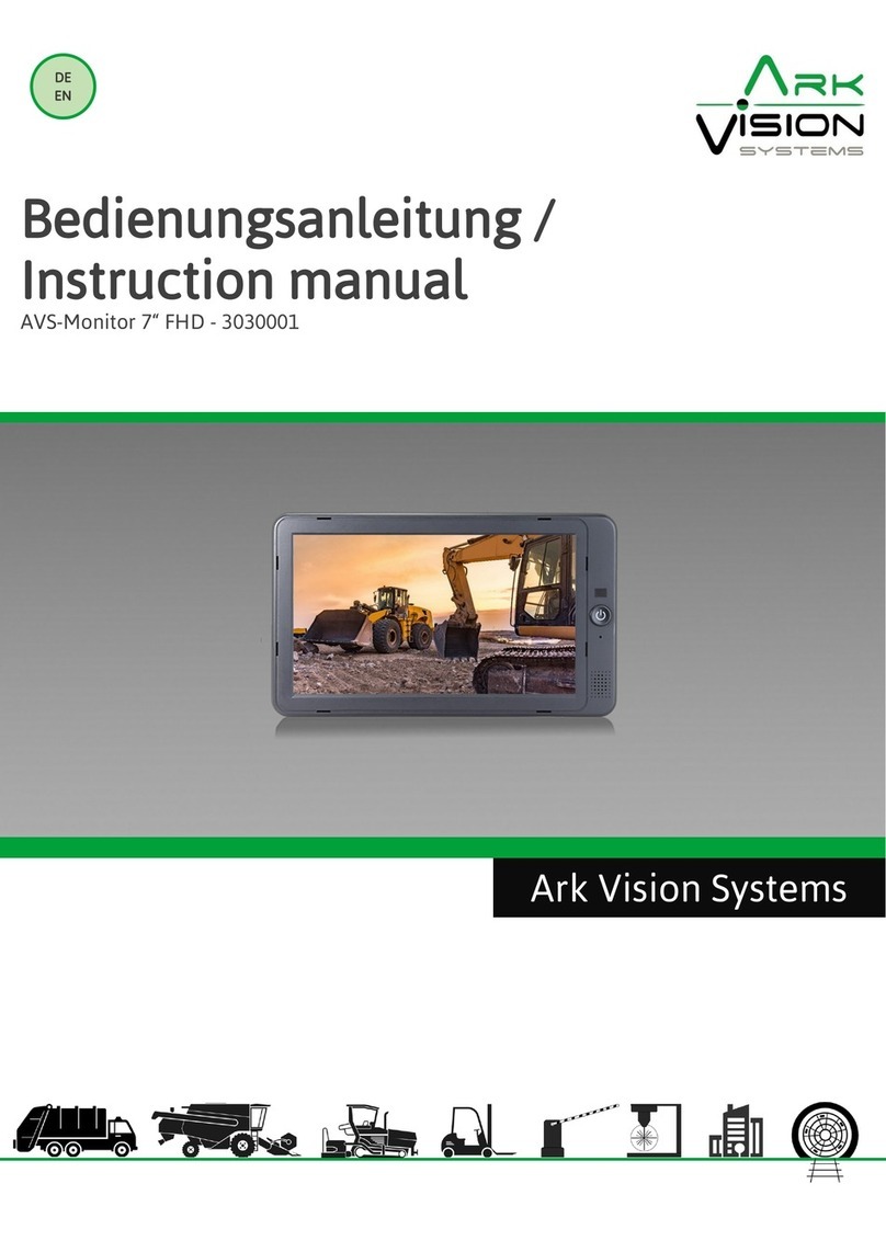
Ark Vision Systems AVS-Monitor 7 FHD User manual

DE
EN
Bedienungsanleitung /
Instruction manuel
Rundumsichtsystem / Bird View System
Ark Vision Systems

Inhaltsverzeichnis /
Table of contents
Anleitung / Manual
Sicherheitshinweise /
Safety instructions
3
Systemskizze /
System drawing
4
Anschlüsse /
Connectors
4
Kameramontage /
Camera mounting
6
Kamera ausrichten /
Align camera
7
Marker ausrichten /
Align marker
8
Menü Login /
Login menu
9
Hauptmenü /
Main Menu
10
Benutzer Einstellung /
User Setup
11
Basis Einstellung /
Basic Setup
12
Videoaufnahme Einstellungen /
Recording Settings
13
Konfiguration des Parkdatensatzes /
Parking Record Configuration
14
Anzeige Einstellung /
Display mode setup
15
Netzwerk Einstellung /
Network Settings
16
Steuerleitung Einstellung /
Trigger line setting
17
Speicher Einstellung /
Storage management
18
Kalibrier-Menü Übersicht /
Calibration Menu Overview
19
Automatische Kalibrierung /
Automatic Calibration
20
Manuelle Kalibrierung /
Manually Calibration
22
Fahrzeugbild /
Vehicle Image
23
Überblendwinkel /
Blending Angle
24
Parklinien /
Parking lines
25
3D Fahrzeugbild Perspektive /
3D vehicle image perspective
26
Rückansicht Perspektive /
Back View Perspective
27
3D-Anzeige anpassen /
3D Display Adjust
28
Video 29
Information 30
Aufnahmezeit /
Record Time
31
Youtube 31
Links 32
2

Der elektrische Anschluss und die erstmalige Inbetriebnahme
dürfen nur von einer Fachkraft nach den Angaben dieser Mon-
tageanleitung erfolgen.
Die Geräte dürfen nur in Betrieb gesetzt werden, wenn sich der
Anwender über die aus der Benutzung resultierenden Risiken
und Gefahren im Klaren ist.
Beschädigte Geräte dürfen nicht in Betrieb genommen wer-
den.
Eine direkte Verbindung mit dem Wechselstromnetz ist unzu-
lässig.
Eine der Kamera vorgeschaltete Sicherung darf nicht über-
brückt oder entfernt werden. Eine defekte Sicherung muss mit
dem vorgeschriebenen Stromwert ersetzt werden. (siehe Kapi-
tel: Technische Daten)
2
Sicherheitshinweise /
Safety instructions
Konformitätserklärung
Als Inverkehrbringer innerhalb Europas haben wir für unsere
Produkte gemäß der EU-Richtlinien und gesetzlichen Vorga-
ben eine Konformitätsbewertung nach den Anforderungen der
jeweiligen „harmonisierten Normen“ durchgeführt.
Sie finden die CE-Kennzeichnung auf dem Produkt sowie auf
der begleitenden Produktdokumentation.
Eine EG-Konformitätserklärung stellen wir Ihnen gerne auf
Anfrage separat zur Verfügung. Bei Veränderungen des Gerä-
tes ist die Einhaltung der Konformität nicht mehr sichergestellt
und die Gewährleistung erlischt.
Bei Verwendung außerhalb der EU ist der Anwender verpflich-
tet, die jeweiligen nationalen Vorschriften zu beachten.
Sicherheitsvorschriften
Wartung und Reinigung
Die Kamera ist wartungsfrei. Die Kamera sollte trotzdem regel-
mäßig kontrolliert und gereinigt werden. Das Kameragehäuse
ist beständig gegen Reinigen mittels Hochdruck–oder Dampf-
strahlgeräten.
Eine verschmutzte Kamerascheibe oder Optik verschlechtert
die Bildqualität.
Reinigen Sie die Scheibe mit einem Tuch oder Schwamm und
sauberem Wasser.
Verwenden Sie auf keinen Fall aggressive Chemikalien oder
Reinigungsmittel.
Entsorgung
Bitte beachten sie lokale Vorschriften der Entsorgung von Ver-
packung und Komponenten. Durch eine umweltgerechte Ent-
sorgung können wertvolle Rohstoffe wiedergewonnen werden.
Declaration of conformity
As a distributor within Europe, we have carried out a conformity as-
sessment for our products in accordance with the EU directives and
legal requirements in accordance with the requirements of the
respective "harmonized standards".
You will find the CE marking on the product as well as on the accom-
panying product documentation.
An EC declaration of conformity can be provided separately on requ-
est. If the device is modified, compliance with the conformity is no
longer ensured and the warranty becomes void.
For use outside the EU, the user is obliged to observe the respective
national regulations.
The electrical connection and initial start-up may only be carried out
by a qualified person in accordance with the information in thes in-
stallation instructions.
The devices may only be put into operation if the user is aware of the
risks and dangers resulting from their use.
It is forbidden to use damaged devices.
A direct connection to the AC power supply is not allowed.
The fuse upstream of the camera does not be bypassed or removed. A
defective fuse must be replaced with the prescribed current value.
(see chapter: Technical Data)
Safety regulations
Maintenance and cleaning
The camera is maintenance-free. The camera should nevertheless be
checked and cleaned regularly. The camera housing is resistant to
cleaning by High pressure or steam jet equipment.
Do not clean the pane dry to to avoid scratches. A dirty camera lens
will reduce the image quality. Clean the lens with a soft cloth or spon-
ge and with clean water.
Never use aggressive Chemicals
or aggressive cleaning agents.
Disposal
Please observe local regulations for disposal of packaging and com-
ponents. Valuable raw materials can be recovered through environ-
mentally friendly disposal.
3
Sprache:
Schriftart Standard = Deutsch
Schriftart Kurisv = Englisch
Language:
Font Standard = German
Kurisv font = English
Systemskizze
Anschluss & Triggerleitungen
IR Controller
CVBS (PAL/NTSC)
USB
AVS-Monitor 7“ FHD
AVS-BirdView 3D
AVS-Camera
190° FHD
10...32V DC
10-32V DC
AVS-Cable 1.X
AVS-Cable 1.X
Trigger
4
Front Cam Fordere Kamera
Rear Cam Rückraum Kamera
Left Cam Linke Kamera
Right Cam Rechte Kamera
AHD (Monitor)

Anschlüsse / Connectors
Vorderseite / Front side
2x SD Card Slot
Status LED
Rückseite / Back side
Wifi Antenne Anschluss
Wifi Antenna Connector
Kamera / Monitor Anschluss
Camera / Monitor Connector
GPS Antenne Anschluss
GPS Antenna Connector
Videoausgang / Trigger Anschluss
Video output / Trigger Connector
Kamera Anschluss
Kamera Links = Anschluss Left
Kamera Rechts = Anschluss Right
Kamera Front = Anschluss Front
Kamera Rück = Anschluss Rear
Steuereinheit Anschluss
rot „RED-VAT“ = 9-32V DC
pink „Pink-ACC“ = 9-32V DC (Zündungsplus)
schwarz „GND“ = 0V GND
Sonstige Anschlüsse
Monitorkabel auf dem Stecker mit der
Beschriftung „AHD“ anschließen
IR-Kabel für die Fernbedienung anschließen
Camera connection
Camera Left = Connection Left
Camera Right = Connection Right
Camera Front = Connection Front
Camera Rear = Connection Rear
Steuereinheit Anschluss
red „RED-VAT“ = 9-32V DC
pink „Pink-ACC“ = 9-32V DC (ignition plus)
black „GND“ = 0V GND
Other connection
Connect the monitor cable to the connector
labelled "AHD
Connect IR cable for remote control
Stromversorgung
Power supply
Fernbedienung´/
Remote Control
5

360°
Kameramontage / Camera mounting
270°270°
Kameras mittig an der jeweiligen Fahrzeugseite montieren /
Mount cameras centrally on the respective side of the vehicle
Alternative
6

Kamera ausrichten / Align camera
Um alle 4 Kamera Bilder einstellen zu können, auf die Taste „Multi“ drücken. /
To adjust all 4 camera pictures, press the "Multi" button.
Optimale Ausrichtung der Kameralinse / Optimal alignment of the camera lens
Beispiel Bild /
Example picture
Optimale Einstellung
Optimum setting
In Ordnung
Setting Ok
Kalibrierung nicht möglich
Calibration not possible
▪ Fahrzeugkontur /
Vehicle contour
7

8
Marker ausrichten / Align marker
Positionierung für 360° oder 270° System /
Positioning for 360° or 270° system
Alternative Positionierung für 270° System /
Alternative Positioning for 270° system
Die Marker sind wie beschrieben zu positionieren und
sollten so nah wie möglich an den Fahrzeugecken ange-
legt werden. Für die Kalibrierung müssen alle Ecken der
Marker in allen Kamerabildern zu sehen sein.
Beispiel: Der Marker hinten rechts am Fahrzeug muss in
der Rückraum- und der rechten Seitenkamera zu sehen
sein.
The markers are to be positioned as described and should
be placed as close as possible to the corners of the vehic-
le. For calibration, all corners of the markers must be vi-
sible in all camera images.
Example: The marker at the rear right of the vehicle must
be visible in the rear camera and the right side camera
.
Länge/Length
Breite/Width

9
Menü Login / Login menu
Um in das Menü zu gelangen, betätigt die „Enter“ Taste auf der Fernbedienung. /
To enter the menu, press the "Menu" button on the remote control
.
Passwort ab Werk lautet „88888888“ unter dem Einstellungssym-
bol kann das Passwort geändert werden. /
The factory password is "88888888" and can be changed under
the settings icon.
Mit der Shift-Taste auf der Fernbedienung wechselt man auf das
Login oder Einstellungssymbol.
The shift key on the remote control switches to the login or set-
tings icon.
Passwort
Login
Passwort ändern /
Change Password
Zurück /
Back
Menu
Shift
Benötigtes Material außerhalb des Lieferumfang:
▪ AVS Kalibrierset
(enthält 4 Kalibriermatten,
Artikelnummer 3040031)
▪ USB Stick
▪ Laptop/PC
▪ PC-Maus (Optional)
Required material outside the scope of delivery:
▪
AVS calibration set
(contains 4 calibration mats,
item number
3040031
)
▪
USB stick
▪
Laptop/PC
▪
PC mouse (optional)
Kalibrierung / Calibration Tools

User Setup
▪ Basis Einstellung
▪ Zeit einstellen
▪ Aufnahme Einstellungen
▪ Display Einstellungen
▪ Netzwerk Einstellungen
▪ Steuerleitungen Einstellungen
Storage / Speicher
▪ Basis Einstellung
▪
Parken Aufnahme
AVM
▪
Kalibrierung
▪
Import und Export von Kalibrierungsdateien,
▪
Fahrzeugmodellwechsel,
▪
Ansichtseinstellungen
▪
andere Funktionen
Video
▪
Verwaltung der Aufzeichnungen
▪
zum Prüfen und Exportieren von Videos vor Ort
Informationen
▪
Informationsdaten
▪
zur Überprüfung und Aktualisierung der Version
von CPU und MCU
User setup
▪ basic function setting,
▪
DVR setting,
▪
display setting,
▪
network setting
Storage management
▪
you can view the SD card
▪
AVM
▪
calibration
▪
calibration file import and export,
▪
vehicle model switching,
▪
view settings
▪
other functions
Video:
▪ Record management,
▪ to check and export videos locally
Information:
▪
Information data
▪
to check and upgrade the version of CPU & MCU
10
Hauptmenü Oberfläche / Main Menu Interface

11
User Setup
Basic Setup: Menü zur Grundeinstellung
Time: Menü für Zeiteinstellungen
DVR: Menü für die Grundeinstellung der Aufnahme
und die Einstellung von Aufnahmeereignissen.
Display: Einstellung des Anzeigemodus.
Network: Schnittstelle für Netzwerkeinstellungen.
Radar: Schnittstelle für Radareinstellungen.
Trigger: Steuerleitungen-Einstellung
(nur im 3D-Modus verfügbar).
Adas Setup: Einstellung der Intelligenzunterstützung.
Anleitung für die Fernbedienung:
▪ SHIFT: Taste zum Umschalten der
Konfigurationselemente.
▪ Links/Rechts: Ändern Sie die Parameter des
aktuellen Konfigurationspunkts.
▪ ESC: Verlassen der Schnelltaste und Rückkehr zum
Hauptmenü.
Hinweis:
Es ist normal, dass dieses System nach dem Speichern
einiger geänderter Konfigurationen automatisch neu
startet.
Basic Setup: Basic setup interface
Time: Time setup interface
DVR: Basic recording setting and recording event set-
ting interface.
Display: Display mode setting.
Network: Network setting interface.
Radar: Radar setting interface.
Trigger: Trigger Line Setting interface
(only available in 3D mode).
Adas setup: Intelligence assistance setting.
Remote control operation instructions:
▪
SHIFT: Switch configuration item button.
▪
Left / right: Modify the parameters of the current
configuration item.
▪
ESC: Exit the shortcut key and return to the main
menu.
Notice:
It is normal for this system automatically restart after
saving some modified configurations.

12
Basis Einstellungen / Basic Setup
AV: Der Standardwert ist PAL. Die optionale PAL/NTSC
-Konfiguration und gilt nur für den CVBS-Ausgang.
Display lcon: Die Funktion zum Ausblenden des Sym-
bols ist standardmäßig auf EIN eingestellt. Wenn sie
auf AUS eingestellt ist, wird das Symbol der Haupt-
schnittstelle ausgeblendet (mit Ausnahme des
Richtungssymbols).
Speed WakeUp: Schnelle Aufwachfunktion, die Stan-
dardeinstellung ist AUS. Wenn diese Funktion auf EIN
gesetzt ist, wird der Bildschirm automatisch aufge-
weckt, wenn die aktuelle Fahrzeuggeschwindigkeit
unter dem eingestellten Geschwindigkeitswert liegt;
wenn die aktuelle Fahrzeuggeschwindigkeit über dem
eingestellten Geschwindigkeitswert liegt, wird der
Bildschirm automatisch in den Standby-Modus ver-
setzt. Bei der Einstellung OFF ist die Geschwindig-
keitsaufwachfunktion ausgeschaltet.
Standby Delay: Automatische Standby-Funktion, die
Standardeinstellung ist AUS. Bei einer Einstellung von
3s geht das System automatisch nach 3s in den Stand-
by-Zustand über, wenn das System nicht bedient wird;
bei einer Einstellung von OFF ist das System immer
eingeschaltet, ohne dass eine Bedienung erfolgt; bei
einer Einstellung von Define kann die Standby-Zeit
individuell konfiguriert werden; der Konfigurationsbe-
reich beträgt 3-30s.
Standby setting: Bildschirm-Standby-
Steuerungsfunktion, die Standardeinstellung ist Bei-
des. Bei der Einstellung AHD wird im Standby nur der
AHD-Ausgang in den Standby-Zustand versetzt; bei
der Einstellung CVBS wird im Standby nur der CVBS-
Ausgang in den Standby-Zustand versetzt; bei der Ein-
stellung Both werden im Standby sowohl der AHD- als
auch der CVBS-Ausgang in den Standby-Zustand ver-
setzt.
Language: Vorübergehend ist nur Englisch verfügbar
AV: The default of standard configuration is PAL. The
PAL/NTSC optional configuration of this configuration
item is only for CVBS output.
Display lcon: icon hidden function is default to be
ON.when set to ON, the main interface icon is display-
ed, when it is set to OFF, the main interface icon is hid-
den (excluding the direction icon).
Speed WakeUp: Speed wake-up function, the default
is OFF. When set to ON, if the current vehicle speed is
lower than the set speed value, the system will auto-
matically wake up the display screen; if the current
vehicle speed is higher than the set speed value, the
system will automatically standby the display screen.
Set to OFF, the speed wake-up function is turned off.
Standby Delay: Automatic standby function, the
default is OFF. When set to 3s, the system will automa-
tically enter the standby state after 3s if there is no
operation on the system; set to OFF, the system will
always be on without any operation; set to Define to
customize the configuration Standby time, the confi-
guration range is 3-30s.
Standby setting: Screen standby control function, the
default is Both. When set to AHD, when in standby,
only AHD output will enter the standby state; set to
CVBS, when in standby, only CVBS output will enter
the standby state; set to Both, when in standby, both
AHD and CVBS outputs will enter the standby state.
Language: Temporarily only English is available

13
Videoaufnahme Einstellungen / Recording Settings
Vehicle ID: Einstellung des Kennzeichens, Standard ist
88888888, bis zu 10 Zeichen können eingestellt werden.
Komprimierung: Einstellung der Videokompression, die Stan-
dardeinstellung ist 4Mbps. 4Mbps (hohe Komprimierung) und
2Mbps (normale Komprimierung) und 1 Mbps (niedrige Kom-
primierung) können eingestellt werden.
Compression: In der Einstellung EIN wird das Video nach dem
Booten automatisch gestartet; in der Einstellung AUS wird das
Video nach dem Booten unter keinen Umständen gestartet.
Duration: Einstellung der Videodauer, Standardminuten sind
3min. Benutzerdefinierte Videodauer können eingestellt wer-
den (Einstellbereich 3-30min).
Record Type: Die Standardeinstellung für die Aufzeichnung ist
"Single". Das System zeichnet vier Einzelkanalbilder auf, wenn
es auf Einzel eingestellt ist; es zeichnet nur ein Vollbild auf,
wenn es auf "FULL" eingestellt ist.
Record Format: Das Videoformat kann auf das AVI-Format
oder das MSV-Format eingestellt werden.
Record Osd: Einstellung für die Videobildschirminformationen;
die Standardeinstellung ist AUS. Wenn die Einstellung auf ON
steht, enthält die Aufnahme Zeit- und Kanalnameninformatio-
nen.
IPC Switch: IPC-Aufnahmeeinstellungen, der Standardwert ist
AUS. Bei der Einstellung EIN wird IPC+Vierkanal-Einzelansicht
während der Aufzeichnung aufgezeichnet.
Record Alarm: Einstellung für den Aufzeichnungsalarm bei
abnormaler Aufzeichnung; der Standardwert ist AUS. In der
Einstellung Ein wird bei einem abnormalen Aufnahmestopp
auf der Hauptschnittstelle eine Alarmmeldung angezeigt; in
der Einstellung AUS wird bei einem abnormalen Aufnahme-
stopp auf der Hauptschnittstelle keine Alarmmeldung ange-
zeigt.
Hinweis:
▪ Wenn der Aufzeichnungstyp auf "Full" eingestellt ist, wird
die Aufzeichnungsqualität nicht durch die Komprimierungs-
konfiguration, sondern durch die RTSP-Konfiguration ge-
steuert. Wenn RTSP auf 1080P eingestellt ist, beträgt die
Aufnahmequalität 8M; wenn RTSP auf D1, 720P eingestellt
ist, beträgt die Aufnahmequalität 2M.
▪ Es ist ein normales Phänomen, dass das System nach der
Änderung einiger Konfigurationselemente neu startet.
▪ Wenn ein Parameter geändert wird, muss er vor dem Been-
den gespeichert werden, da sonst die Änderung ungültig
wird.
▪ Wenn die Videoqualität auf 4mbps eingestellt ist, wird das
Video in kurzer Zeit überschrieben.
Vehicle ID: License plate number setting, default is 88888888,
up to 10 characters can be set.
Compression: Video compression setting, the default is 4Mbps.
4Mbps(high compression) and 2Mbps (normal compression)
and1 Mbps (low compression) can be set.
Auto Record: Automatic recording switch, the default is ON.
Set to ON, the video will start automatically after booting; set
to OFF, the video will not start under any circumstances after
booting.
Duration: Video duration setting, default minute is 3. 3Min,
5Min, 10Min and user-defined video duration can be set
(setting range 3-30min).
Record Type: The default record type is Single. The system will
record four single channel’s image when set to be Single; it
will only record one full screen when set to be FULL. 15
Record Format: Default format is AVI.The video format can be
set to AVI format or MSV format.
Record Osd: Video screen information setting, the default is
OFF. When set to ON, the recording will have time and channel
name information; if set to OFF, the recording will have no
time and channel name information.
IPC Switch: IPC recording settings, the default value is OFF. Set
to ON, IPC+four-channel single view will be recorded during
recording; set to OFF, IPC will not be recorded during record-
ing.
Record Alarm: Recording abnormal alarm setting, the default
is OFF. When set to On, if the recording stops abnormally, the
main interface will display an alarm prompt; if set to OFF,
when the recording stops abnormally, the main interface will
not display the alarm prompt.
Notice:
▪
When the recording type is set to "Full", the recording qua-
lity will not be controlled by the Compression configurati-
on, but will be controlled by the RTSP configuration. If the
RTSP is set to 1080P, the recording quality is 8M; if the
RTSP is set to D1, 720P, the recording quality is 2M.
▪
It is normal phenomenon for the system will restart after
modify some configuration items.
▪
If any parameter is modified, it must be saved before
exiting, otherwise the modification will be invalid.
▪
When the video quality is set to 4mbps, the video will be
overwritten in a short period of time

14
Konfiguration des Parkdatensatzes /
Parking Record Configuration
Swtich: Schalter für die Videoaufzeichnung beim Par-
ken, Standardeinstellung ist OFF. Wenn er auf ON ge-
stellt ist und Sie das Auto parken, wird es nach Ablauf
der Zeit in der Konfiguration der verzögerten Abschal-
tung in den Abschaltzustand übergehen; wenn er auf
OFF gestellt ist, wird es sofort nach dem Parken in den
Abschaltzustand übergehen.
Voltage: Spannungskonfiguration, die Standardein-
stellung ist 11,4 V. Wenn der Schalter auf ON konfigu-
riert ist, geht er sofort in den Standby-Zustand über,
wenn die aktuelle Spannung nach dem Anhalten nied-
riger als die konfigurierte Spannung ist; wenn die ak-
tuelle Spannung höher als die konfigurierte Spannung
ist, geht er in den Shutdown-Zustand über, nachdem
die Zeit in der Delay-Shutdown-Konfiguration abge-
laufen ist. 9-24V ist optional.
Delay shutdown: Konfiguration der Parkaufzeich-
nungszeit, die Standardeinstellung ist 30 Minuten. Es
kann ein Bereich von 1-90 Minuten eingestellt wer-
den.
Swtich: parking video recording switch, the default is
OFF. When it is set to ON and when you park the car, it
will enter the shutdown state after the time in Delay
shutdown configuration expire ; when it is set to OFF,
it will enter the shutdown state immediately after par-
king.
Voltage: Voltage configuration, the default is 11.4V.
When the Switch is configured to be ON: it will imme-
diately enter the standby state if the current voltage is
lower than the configured voltage after stopping; if
the current voltage is higher than the configured vol-
tage, it will enter the shutdown state after the time in
delay shutdown configuration expired. 9-24V is optio-
nal.
Delay shutdown: parking recording time configurati-
on, the default is 30min. 1-90min range can be set.

15
Anzeige Einstellung / Display mode setup
SD Screen Adjustment: Einstellung der Parameter des CVBS
-Ausgangsbildschirms.
Logo Setup: Ersetzen des Bootlogos. Hinweis: Derzeit wird
der Import eines Logos im BMP-Format mit einer Tiefe von
24 Bit (1920x1080) unterstützt.
Blending Region: Schaltet die Überlappung in der Blending
Zone Ein oder aus.
View Mode: Wähle zwischen 2D & 3D Ansicht. Bei der Ein-
stellung 2D ist der Anzeigeeffekt 2D-Rundumsicht + Einzel-
ansicht; bei der Einstellung 3D ist der Anzeigeeffekt 2D-
Rundumsicht + 3D-Ansicht.
Display Direction: Wähle zischen horizontaler oder vertika-
ler Ansicht. Menü und Bilderansichten werden mit gedreht.
View Ratio: Wähle das Verhältnis zwischen Rundumsicht
und Einzelbildansicht.
Compatibility Mode: Einstellungen für den Kompatibilitäts-
modus; die Standardeinstellung ist EIN. In der Einstellung
EIN ist die Kompatibilität aller Bildschirme besser; in der
Einstellung AUS ist der Anzeigeeffekt besser. (Der Modus
Hoch ist vorübergehend nicht verfügbar).
Front Cursor: Die Konfiguration des Cursor-Schalters für die
vordere Einzelansicht; die Standardeinstellung ist AUS. In
der Einstellung EIN wird der Cursor in der vorderen Einzel-
ansicht angezeigt; in der Einstellung AUS wird der Cursor in
der vorderen Einzelansicht nicht angezeigt.
Back Cursor:: Die Konfiguration des Cursor-Schalters für die
hintere Einzelansicht; die Standardeinstellung ist AUS. Bei
der Einstellung EIN wird der Cursor in der hinteren Einzel-
ansicht angezeigt; bei der Einstellung AUS wird der Cursor
in der hinteren Einzelansicht nicht angezeigt.
Vehicle Model Offset: Schnellzeichenkonfiguration, die
Standardeinstellung ist AUS. Bei der Einstellung EIN wird
der hintere Einzelansichtsbildschirm etwa 3 Sekunden nach
dem Einschalten angezeigt; bei der Einstellung AUS wird
das Kofferraumlogo etwa 3 Sekunden nach dem Einschal-
ten angezeigt.
Default View: Standardwert ist Dual +Vorne.
Hinweis: Es ist ein normales Phänomen, dass das System
nach der Änderung einiger Konfigurationspunkte neu star-
tet.
SD Screen Adjustment: CVBS output screen parameter ad-
justment. (Note: re-adjustment is required after switching
between NTSC and PAL).
Logo Setup: Replacement of the boot logo. Note: Currently,
it is supported to import a 24-bit deep 1920x1080 BMP for-
mat logo image.
Blending Region: Switch for whether the loop view overlap
area is overlapped or not, the default is ON. Set to ON, the
overlapping area overlaps; set to OFF, the overlapping area
does not overlap.
View Mode: Display mode switching, the default is 2D. 2D
mode or 3D mode can be set.When set to 2D, the screen
display effect is 2D bird view + single view; when set to 3D,
the screen display effect is 2D bird view + 3D ring view.
Display Direction: Horizontal and vertical screens swit-
ching, the default is Horizontal. When set to Horizontal, the
screen is rendered in a horizontal screen effect; when set to
Vertical, the screen is rendered in a vertical screen effect.
View Ratio: Choose the ratio between single view and bird
view.
Compatibility Mode: Compatibility mode settings, the
default is ON. When set to ON, the compatibility of all
screens is better; when set to OFF, the screen display effect
is better.(High mode is temporarily unavailable).
Front Cursor: The front single view cursor switch configura-
tion, the default is OFF. When set to ON, the front single
view displays the cursor; when set to OFF, the front single
view does not display the cursor.
Back Cursor: The back single view cursor switch configurati-
on, the default is OFF. When set to ON, the back single view
displays the cursor; when set to OFF, the back single view
does not display the cursor.
Vehicle Model Offset: Quick drawing configuration, the
default is OFF. When set to ON, the rear single-view screen
will be displayed about 3s after power-on; if it is set to OFF,
the boot logo will be displayed about 3s after power-on.
Default View: Default value is Dual +Front.
Notice: It is normal phenomenon for the system will restart
after modify some configuration items.

16
Netzwerk Einstellung / Network Settings
IP-Adresse: Einstellung der IP-Adresse. Der Standard-
wert ist 192.168.117.117.
RTSP-Typ: Einstellung der Auflösung für die Netzwerk-
wiedergabe von Videostreams, Standardwert ist 720P.
D1/720P/1080P wählbar.
Wifi switch: Standardkonfiguration ist EIN, wenn der
Wi-Fi-Schalter auf EIN gestellt ist, kann eine normale
Wi-Fi-Verbindung hergestellt werden; wenn er auf
AUS gestellt ist, ist die Wi-Fi-Funktion ausgeschaltet
und kann nicht verbunden werden.
Wifi-Name: Der Wi-Fi-Name kann bis zu 16 Zeichen
lang sein, der Standardwert ist FHD360_T5.
Wi-Fi-Passwort: Das Standard-Passwort lautet
88888888. Wi-Fi-Passwort: Stellen Sie mindestens 8
und maximal 16 Zeichen ein.
Hinweis:
Wenn der RTSP-Typ auf 1080P eingestellt ist, muss der
Kompatibilitätsmodus (Kompatibilitätsmodus) auf
AUS gesetzt werden, da es sonst zu Darstellungsfeh-
lern wie verschwommenen Bildschirmen und horizon-
talen Streifen kommen kann.
IP Address: IP Address Setting. Default value is
192.168.117.117.
RTSP Type: Network playback video stream resolution
setting,default value is 720P. D1/720P/1080P sel-
ectable.
Wifi switch: Default configuration is ON,When the Wi-
Fi switch is set to ON, it can connect to Wi-Fi normally;
when it is set to OFF, the Wi-Fi function is turned off
and cannot be connected.
Wifi Name: The Wi-Fi name setting can be up to 16
characters, the default value is FHD360_T5.
Wifi password: Default password is 88888888. Wi-Fi
password setting, set a minimum of 8 characters and a
maximum of 16 characters.
Notice:
When the RTSP Type is set to 1080P, the Compatibility
Mode (compatibility mode) needs to be set to OFF,
otherwise it is prone to display defects such as blurred
screens and horizontal stripes.

Das Konfigurationselement ist nur verfügbar, wenn
der Ansichtsmodus als 3D konfiguriert ist; wenn der
Ansichtsmodus als 2D konfiguriert ist, ist das Konfigu-
rationselement im Ausblendungszustand
Trigger Priority: Steuerleitung Priorität. Standardwert
ist "None" (aus). Bei Einstellung auf "None" wird zum
Beispiel die hintere Kamera ausgelöst, wird die Rück-
fahrkamera in einer Panoramaansicht angezeigt.
Wenn zu diesem Zeitpunkt auch die linke Kamera
ausgelöst wird, wird die Rückfahrkamera weiterhin im
Panorama angezeigt. Die linke Kamera wird erst an-
gezeigt, wenn die Auslösung der Rückfahrkamera ab-
geschlossen ist.
Steuerleitung Yellow, White, Brown & Red:
Auswahlmöglichkeit Dual+Left, Dual+Right, Du-
al+Front, Dual+Back, Single_Right, Single_Left, Sin-
gle_Front, Single_Back, Quad, Full Dual, IPC.
Save: Speichern der Parametereinstellungen.
Exi
The configuration item is only available when the
view mode is configured as 3D; if the view mode is
configured as 2D, the configuration item is in blanking
state
Trigger Priority: Trigger priority, default value is None.
When set to None: For example, when the rear line is
triggered, the rear view camera is displayed in a pano-
ramic view. At this time, if the left road is also trigge-
red, the back road camera is still displayed in the pa-
norama. The left side camera will not be displayed
until the back road trigger is completed.
Trigger line Yellow, White, Brown & Red:
Selection option Dual+Left, Dual+Right, Dual+Front,
Dual+Back, Single_Right, Single_Left, Single_Front,
Single_Back, Quad, Full Dual, IPC.
Save: Save parameter adjustments.
:Exi
17
Steuerleitung Einstellung / Trigger line setting

Speicher Einstellung / Storage management
18
Funktionsbeschreibung: Die Aufnahmefunktion unterstützt
2 SD-Karten, und die U-Disk wird nur für Programm-
Upgrades oder Datei-Import/Export verwendet.
Storage Management:
Total
: Gesamtkapazität der SD-Karte/U-Disk.
Used
: Die genutzte Kapazität der SD-Karte/U-Disk.
Free
: Die verbleibende Kapazität der SD-Karte/des U-
Datenträgers.
Format
: SD-Karte oder U-Disk formatieren. SD-
Kartenverwendung: Derzeit nicht verfügbar
Management Logs:
ALL: Wählen Sie alle Protokolle aus; das ausgewählte Proto-
koll wird blau angezeigt.
None: Das nicht ausgewählte Protokoll wird in weißer Far-
be angezeigt.
Delete: Löscht das ausgewählte Protokoll.
Export: Ausgewählte Protokolle exportieren.
Beenden und Return-Taste.
Hinweis:
1) Wenn der USB-Stick und die SD-Karte nicht ordnungsge-
mäß funktionieren, werden auf der Panorama-
Hauptschnittstelle und auf der Speichermenüschnittstel-
le unterschiedliche Symbole angezeigt.
2) Entfernen Sie das USB-Flash-Laufwerk nicht, wenn Sie
formatieren, Systemprotokolle exportieren und
Spleißergebnisse exportieren.
3) Wenn Sie Schreibvorgänge im Zusammenhang mit der
SD-Karte durchführen, entfernen Sie z. B. nicht die SD-
Karte, ohne die Aufnahme zu stoppen, die SD-Karte zu
formatieren oder das Systemprotokoll zu löschen.
4) Unterstützung der Schleifenaufzeichnung. Wenn der
verfügbare Speicherplatz auf allen SD-Karten im System
weniger als 1024 MB beträgt, werden die ersten 10 Vi-
deodateien für die normale Aufnahme gelöscht.
Feature Description: recording function supports 2 SD
cards, and the U disk is only used for program upgrades or
file import/export.
Storage Management:
Total: Total capacity of SD card/U disk.
Used: the used capacity of the SD card/U disk.
Free: The remaining capacity of the SD card/U disk.
Format: format SD card or U disk. SD Card Usage:Currently
unavailable
Management Logs:
ALL: Select all logs.The selected log is displayed in blue.
None: Unselect logs.The unselected log is displayed in whi-
te
Delete: Delete the selected log.
Export: Export selected logs.
Exit and return key.
Notice:
1) When the U disk and SD card work abnormally, there
will be different icon prompts on the panoramic
main interface and the storage menu interface.
2) Do not remove the USB flash drive when formatting,
exporting system logs, and exporting splicing results.
3) When performing write operations related to the SD
card, for example, do not remove the SD card wit-
hout stopping recording, formatting the SD card or
clearing the system log.
4) Support loop recording. When the available space of
all SD cards in the system is less than 1024M, the ear-
liest created 10 video files will be deleted for normal
recording.

Kalibrier-Menü Übersicht / Calibration Menu Overview
19
Automatic Calibration: Automatische Kalibrierung.
Calibration File: Exportieren von Kalibrierungsbildres-
sourcen und Importieren von Kalibrierungsdateien
(wird hauptsächlich bei der PC-Kalibrierung verwen-
det)
Vehicle Type: Wechseln Sie den Fahrzeugtyp.
Surround View: Einstellung des Überlappungswinkels
und des umgebenden Sichtbereichs.
Parking Line: Einstellung des Rückfahr-Cursors.
3D Perspective: Einstellung der 3D-Perspektive (Diese
Konfigurationsoption wird nur angezeigt, wenn der
Ansichtsmodus als 3D konfiguriert ist; wenn der An-
sichtsmodus als 2D konfiguriert ist, ist die Konfigurati-
onsoption ausgeblendet).
Back View Perspective: Einstellung des 3D-
Ansichtspunkts für die Rückansicht (Diese Konfigurati-
onsoption wird nur angezeigt, wenn der Ansichtsmo-
dus als 3D konfiguriert ist; wenn der Ansichtsmodus
als 2D konfiguriert ist, ist die Konfigurationsoption
ausgeblendet)
3D Display Adjust: 3D-Anzeigeeinstellung (Diese Kon-
figurationsoption wird nur angezeigt, wenn der An-
sichtsmodus als 3D konfiguriert ist; wenn der Ansichts-
modus als 2D konfiguriert ist, ist die Konfigurationsop-
tion ausgeblendet)
Automatic Calibration: Automatic Calibration.
Calibration File: Export calibration picture resources
and import calibration files.(mainly used when in
PC‘s calibration)
Vehicle Type: Change the car model type page.
Surround View: Overlap angle and surrounding visual
range setting.
Parking Line: Reversing cursor adjustment.
3D Perspective: 3D perspective view point setting.
(This configuration item is displayed only when the
view mode is configured as 3D; if the view mode is
configured as 2D, the configuration item is in blanking
state).
Back View Perspective: 3D rear view view point set-
ting.(This configuration item is displayed only when
the view mode is configured as 3D; if the view mode is
configured as 2D, the configuration item is in blanking
state)
3D Display Adjust: 3D display setting.(This configurati-
on item is displayed only when the view mode is con-
figured as 3D; if the view mode is configured as 2D,
the configuration item is in blanking state)

Automatische Kalibrierung /
Automatic Calibration
20
Cancel: Klicken Sie auf diese Schaltfläche, um die Ka-
librierungsschnittstelle zu verlassen.
Calibrate: Automatische Kalibrierung: Klicken Sie auf
diese Schaltfläche, um den automatischen Kalibrie-
rungsmodus zu starten.
Calibrate Log: Anzeige des Kalibrierungsprotokolls.
Vorsichtsmaßnahmen:
1) Jede Kamera sollte die 2 nahegelegenen
Kalibrierungsmatten vollständig sehen und
nicht durch Objekte blockiert werden.
2) Der Kalibrierungsmast auf dem Kamerabild-
schirm darf nicht stark verzerrt sein.
3) Die Kalibrierungsmatten sollten kein stark
reflektiertes Licht aufweisen.
Cancel: Cancel button, click this to exit calibration
interface.
Calibrate: Automatic calibration button, click to enter
automatically calibration mode.
Calibrate Log:Display of calibration log.
Precautions:
1) Each camera should fully see the 2 nearby calibra-
tion mats and cannot be blocked by objects.
2) The calibration mast in the camera screen cannot
be severely distorted.
3) The calibration mats should not have serious re-
flected light.
Other manuals for AVS-Monitor 7 FHD
1
Table of contents
Other Ark Vision Systems Machine Vision System manuals

Ark Vision Systems
Ark Vision Systems AVS-QuadUnit FHD User manual

Ark Vision Systems
Ark Vision Systems AVS-Monitor 7 FHD User manual

Ark Vision Systems
Ark Vision Systems AVS-SplitUnit FHD User manual

Ark Vision Systems
Ark Vision Systems AVS-Monitor 7 Quad FHD User manual

Ark Vision Systems
Ark Vision Systems AVS-Wireless User manual

Ark Vision Systems
Ark Vision Systems ArkVisionUnit 7 User manual