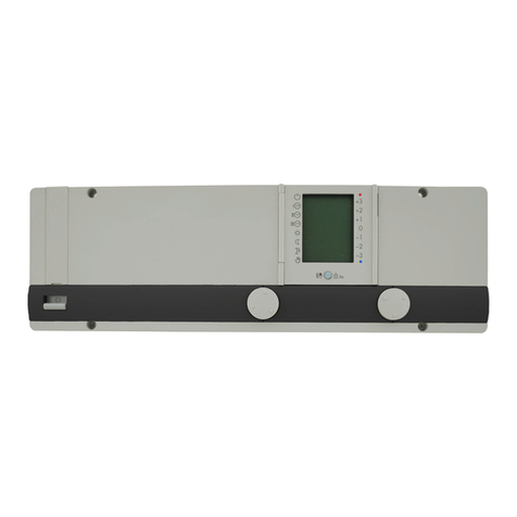
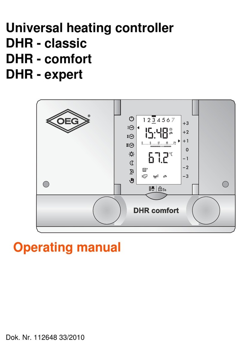
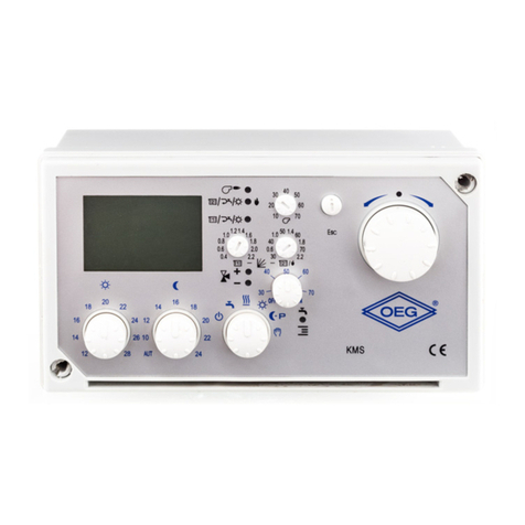
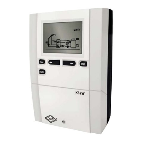
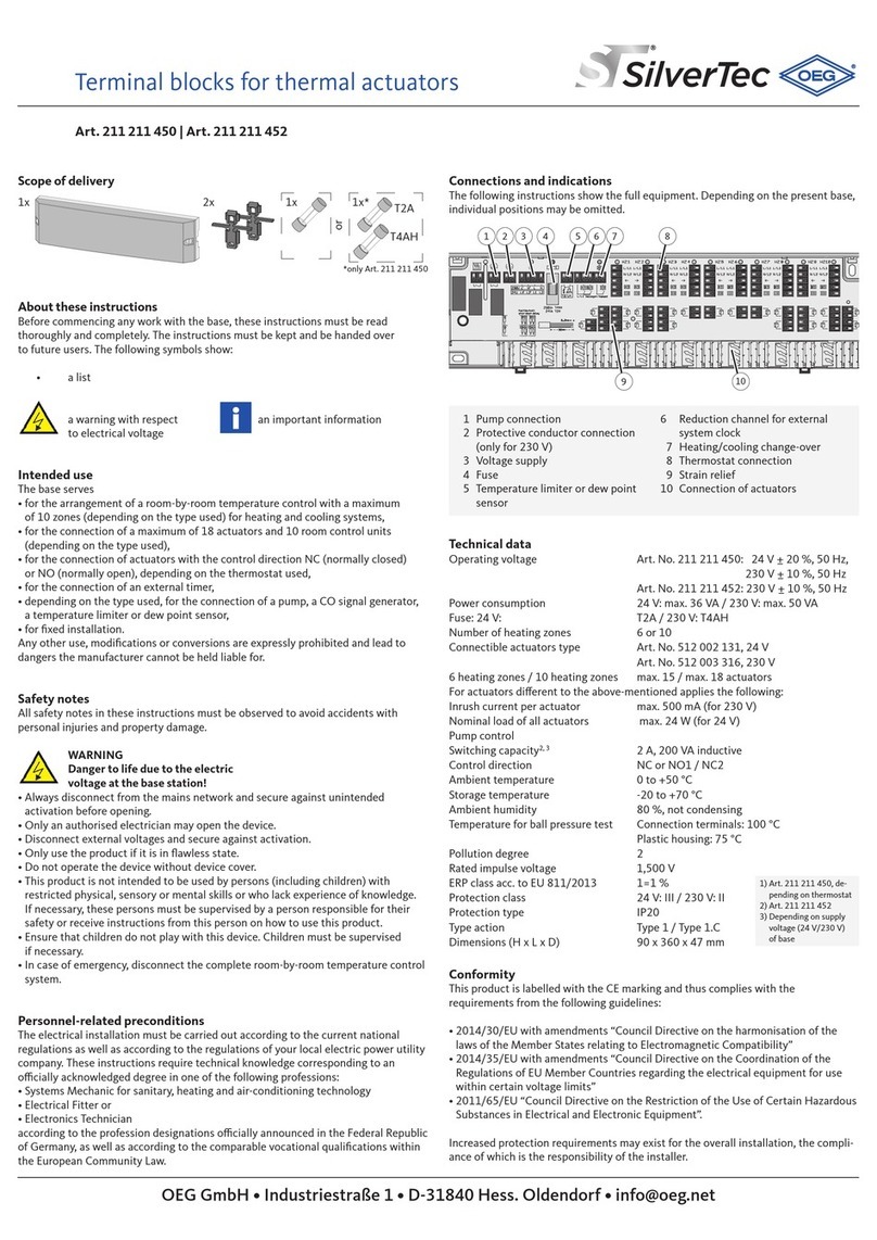
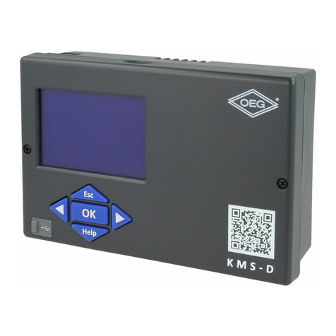
OEG KSW-E Series User manual

KSW-E*, KSW*, KS2W*
Verschilregelaar
KSW-E*: 1 uitgang, 4 ingangen
KSW*: 2 uitgang, 6 ingangen
KS2W*: 3 uitgang, 6 ingangen
DUT
ENG Differential controller
KSW*: 1 output, 4 inputs
KSW*: 2 outputs, 6 inputs
KS2W*: 3 outputs, 6 inputs
DEU Differenzregler
KSW-E*: 1 Ausgäng, 4 Eingänge
KSW*: 2 Ausgänge, 6 Eingänge
KS2W*: 3 Ausgänge, 6 Eingänge
FRE Régulation différentielle
KSW-E*: 1 sortie, 4 entrées
KSW*: 2 sorties, 6 entrées
KS2W*: 3 sorties, 6 entrées
ITA Regolatori differenziali
KSW-E*: 1 uscita, 4 ingressi
KSW*: 2 uscite, 6 ingressi
KS2W*: 3 uscite, 6 ingressi


ENGDEUDUT
FREITA
Differential controllers
KSW-E*, KSW*, KS2W*
Differenzregler
KSW-E*, KSW*, KS2W*
Verschilregelaar
KSW-E*, KSW*, KS2W*
Régulation différentielle
KSW-E*, KSW*, KS2W*
Regolatori differenziali
KSW-E*, KSW*, KS2W*


ENG
5
INTRODUCTION
Differential controllers KSW-E*, KSW*, KS2W* are modern designed, microprocessor-
driven devices made with digital and SMT technology.
These devices are intended for regulating domestic hot water warming by means of solar
collectors or for regulating domestic hot water warming by means solid fuel boiler, electric
heater or other energy resources.
Differential controllers KSW-E*, KSW*, KS2W*
For initial setup see Initial controller setup, page 8!

ENG
6
CONTENTS
USER MANUAL
Appearance of controller ............................................................................................7
Initial controller setup...................................................................................................8
Graphic LCD display ................................................................................................ 10
Description of symbols shown on the display .......................................................... 11
Display for help, notices and warnings ......................................................................13
Menu entry and navigation ...................................................................................... 14
Menu structure and description ................................................................................ 15
Temperature settings................................................................................................ 18
User functions .......................................................................................................... 19
Operation mode selection......................................................................................... 20
Time program settings ............................................................................................. 21
Basic settings ........................................................................................................... 24
Data overview .......................................................................................................... 26
SERVICE MANUAL
Controller parameters and auxiliary tools ................................................................. 27
Basic parameters.................................................................................................. 27
Service parameters ............................................................................................. 30
Heat metering parameters ................................................................................... 34
Heat metering........................................................................................................34
Parameters for available outputs programming.....................................................36
Factory settings ....................................................................................................... 42
INSTALLATION MANUAL
Controller installation ............................................................................................... 43
Wall installation......................................................................................................... 43
Marking and description of temperature sensors ..................................................... 44
Controller’s electric connection..................................................................................45
Flow meter installation ............................................................................................. 46
Temperature simulation mode...................................................................................46
Flow setup and test of RPM control...........................................................................46
Technical data ...........................................................................................................47
Guarantie...................................................................................................................49
Declaration of conformity...........................................................................................50
Disposal of old electrical and electronic equipment...................................................50
Hydraulic and electric schemes...............................................................................237
Installation protocol..................................................................................................267

User and settings manual
ENG
7
1 - Graphic display.
2 - button (Esc - return to previous).
3 - button (one step back, decrease).
4 - USB connector for connecting personal computer.
5 - button (enters a menu, confirms selection).
6 - button (Help).
7 - button (one step forward, increase).
USER MANUAL
APPERANCE OF CONTROLLER
1
2
3
4 5 6 7

User and settings manual
ENG
8
INITIAL CONTROLLER SETUP
KSW-E*, KSW*, KS2W* differential controllers are equipped with an innovative solution
“Easy start”, which allows initial setup of the controller in only two steps.
When you connect the controller to the power supply for the first time, the software ver-
sion is shown. Next, the first step appears on the screen.
Using buttons and you select the required language.
Press the button to confirm the selected language.
After selecting the language, the controller requires
confirmation of the selection by pressing the
button.
If you accidentally selected the wrong language, go
back to reset the language by pressing button .
If you cannot find the required language on the first screen, move to the fol-
lowing screens by pressing the button .
STEP 1

User and settings manual
ENG
9
Selected hydraulic scheme can be later changed with service parameter S1.1.
Controller RESET!
Disconnect the controller from the power supply. Press and hold the button
and switch on power supply. The controller resets and goes to initial
setup.
CAUTION!
By selecting ‘reset’ all previous controller settings are erased.
Next, you select a hydraulic scheme for the controller
function. Move between schemes by means of buttons
and .
Confirm the selected scheme by pressing the
button.
STEP 2
After you selected the scheme, the controller requires
confirmation of the selection by pressing the
button.
If you accidentally selected the wrong scheme, go back
to reset the scheme by pressing button .

User and settings manual
ENG
10
Controller operation mode
Active
functions
Measured
temperatures,
state of output
and other data
Time and date
All important data of controller operation are shown on the graphic LCD display.
Advanced review of temperatures:
Measured temperature
Set point temperature
DESCRIPTION AND DESIGN OF THE MAIN DISPLAY:
For temperature and other data review we use buttons and .
Number of sensors and other data seen on the display depends on the selected hydraulic
scheme and controller settings.
2s
Which data are shown on the basic display depends on the selected scheme.
If we want to change the displayed information, press button or to
select the required data and confirm it by holding button for 2 se-
conds.
Messages
and warnings
State
of output
Diagram
of hydraulic
scheme
Measured
temperatures
GRAPHIC LCD DISPLAY

User and settings manual
ENG
11
All important data about controller operation are seen on the LCD display.
We browse through data by means of buttons and .
OPERATION MODE SYMBOLS
DESCRIPTION OF SYMBOLS SHOWN ON THE DISPLAY
Symbol Description
Controller operates in automatic mode
Controller operates automatically according to program timer , ,
or . ON and OFF indicates status of the timer.
Manual operation mode
Controller is turned OFF
One-time warming of domestic hot water function is activated
Holiday mode function is activated
Return cooling of storage tank is activated
Protection against overheating of the solar collectors is activated
Protection against freezing of the solar collectors is activated
Protection against legionella is activated
State of outputs ON*
OFF*
or Output has a function pogrammed (parameters F1, F2)*
RPM stage indication for pumps R2 and R3*
Indication impulsive pump mode - tube collectors (Parameter S2.2)
Inverted operation of output
* Depends on the controller model.

User and settings manual
ENG
12
TEMPERATURE AND OTHER DATA SYMBOLS
SYMBOLS FOR NOTICE AND WARNINGS
Symbol Description
Notice
In case of exceeding the maximum temperature or activation of pro-
tection function, the controller indicates the event with flashing symbol
on the display. If the maximum temperature is no longer exceeded or if
the protection function is turned off, a lited symbol indicates a recent
event.
Press to open the screen to check notifications.
Warning
In the event of sensor failure, pump error or flow sensor error, the
controller indicates the failure with flashing symbol on the display. If
the issue is resolved or no longer present, a lited symbol indicates a
recent event.
Press to open the screen for warnings.
Symbol Description
Solar collectors temperature
Temperature of storage tank or heat accumulator - bottom
Temperature of storage tank or heat accumulator - top
Liquid fuel boiler temperature
Solid fuel boiler temperature
Pellet boiler temperature
Outdoor temperature
Swimming pool water temperature
Stand- pipe or return- pipe temperature
Measured temperature
Set point or calculated temperature
T1, T2, T3, T4, T5, T6
Temperature sensors T1, T2, T3, T4, T5 and T6

User and settings manual
ENG
13
Delete warning and notification logs
Pressing this button will erase notification and warning log. All sensors that
are not connected will be deleted from the list of failures.
Note: Failures of sensors that are required for controller operation can not
be deleted.
Press button to open the screen for help, notices and warnings is opened.
Short manual
Short manual for use of the controller.
Controller version
Overview of controller type and software version.
Notices
Log of maximum temperatures exceeds and activated protection functions.
By pressing the buttons and move through the list of notifications.
Press to exit the list.
Warnings
Log of sensors, pump or flow meter failures.
By pressing the buttons and move through the list of warnings.
Press to exit the list.
DISPLAY FOR HELP, NOTICES AND WARNINGS
Available posibilities:

User and settings manual
ENG
14
The menu is simplified with the help of graphic symbols.
To enter the menu, press the button .
Move around the menu using the buttons and , with the button you
confirm your selection.
By pressing the button you return to the previous screen.
If no button is pressed for several seconds, the screen illumination goes out.
In such case pressing any button switches on backlight illumination.
MENU ENTRY AND NAVIGATION

User and settings manual
ENG
15
MENU STRUCTURE AND DESCRIPTION
TEMPERATURE SETTINGS
Set-point temperature in d. h. w. storage tank or heat accumulator - bottom*
Desired temperature of domestic hot water tank or heat accumulator - top*
Desired swimming pool water temperature
Desired return-pipe temperature
USER FUNCTIONS
One - time domestic hot water warming
Holiday operation mode
Cancelation of user function
OPERATION MODE
Automatic operation
Controller operation - switch-off
Manual operation mode
TIME PROGRAMS
SELECTION OF ACTIVE TIME PROGRAM
Without time program
Time program #1
Time program #2
* The “n” symbol marks the successive number of d. h. w. storage tank or heat accumulator, if there is more than
one d. h. w. storage tank or heat accumulator present in the system. The “Tx” symbol marks the number of the
sensor for which the thermostatic operation of the available output is programmed.

User and settings manual
ENG
16
Time program #3
Time program #4
TIME PROGRAM EDITOR
Time program #1
Time program #2
Time program #3
Time program #4
BASIC SETTINGS
Language selection
Time and date
Duration of active display illumination and menu autoexit
Intensity of active display illumination
Intensity of inactive display illumination
Display contrast
DATA OVERVIEW
Numeric and graphic display of acquired energy
Diagrams of measured temperatures for last week
Diagrams of measured temperatures for current day
Output operation time counter
Special service data
DISPLAY SETTINGS

User and settings manual
ENG
17
BASIC PARAMETERS
Differences and hysteresis
Minimum and maximum temperatures
Operation settings.
SERVICE PARAMETERS
Service parameters 1
Service parameters 2
Service parameters 3
PARAMETERS FOR HEAT METERING
PARAMETERS FOR AVAILABLE OUTPUTS PROGRAMMING
Free programming of the first available relay output operation
Free programming of the second available relay output operation.*
FACTORY SETTINGS
Reset of all controller parameters
Reset of time programs
Reset of all controller settings and restart of initial setup
Save user settings
Load user settings
* Depends on model of controller.

User and settings manual
ENG
18
By pressing buttons , and you choose the required temperature, and a new
window opens:
Set the set-point temperature with buttons , and confirm with button .
Exit settings with button .
Graphic review
of settings
Sensor location
Value of the last
confirmed setting
Default value
Current value
of set-point temperature
(analogue mode)
Setting range
Current value
of set-point temperature
(numeric mode)
TEMPERATURE SETTINGS
In the menu “TEMPERATURE SETTINGS” you can set the set-point temperature for the sen-
sors shown.

User and settings manual
ENG
19
USER FUNCTIONS
User functions enable additional comfort and benefits when using the controller. In menu,
the following user functions are available:
One-time domestic hot water warming
One-time d. h. w. warming is possible only by schemes with a liquid fuel
boiler, heat pump or electric heater.
Use this function when you want to immediately turn on the d. h. w. warming.
By pressing buttons and select function and activate it by pressing the button .
You leave settings by pressing the button .
Holiday mode
Holiday mode is enabled by schemes with solar collectors, liquid fuel boil-
er, heat pump or electric heater.
Holiday mode activates cooling down of the storage tank during night time to minimum
temperature (P2.4). Cooling is carried out through solar collectors. This way we enable the
solar system to operate normally the next day for as long time as possible.
Holiday mode is activated until selected date. After you have activated the Holiday mode,
choose the Holiday mode icon again. A new screen is displayed, where you can set the
date when the Holiday mode should expire.
Function switch-off
You can deactivate a currently active function at any time by selecting the icon with
buttons and , and confirming it with the button.

User and settings manual
ENG
20
OPERATION MODE SELECTION
In group “OPERATION MODE” select the required controller operation mode. You can select
between automatic mode, controller switch-off and manual mode.
Description of operation mode:
You choose the required mode by pressing buttons , and confirm it by pressing
button .
You exit the setting by pressing button .
Manual mode
This mode is used for testing the heating system or in case of a malfunction.
Every output can be manually activated or deactivated.
By pressing buttons and , move
through move among individual outputs R1-
R3*. Select the output of which state you
want to change by pressing the but-
ton. Values ON, OFF, AUTO or pump RPM
40 %, 55%, 70 % and 85 % will begin to
flash. Now you can change the output sta-
tus with buttons and .
Confirm the selection by pressing the
button.
Exit the setting by pressing the
button.
Controller switch-off
Controller is not performing system control and switches off all outputs.
All temperatures are still measured and shown. Protection functions are still
active and able to switch on output.
Automatic operation
Heating is active.
In the automatic operation mode, the controller enables activation and deacti-
vation of additional energy sources (for example: oil boiler, heat pump, electric
heater, etc.).
To activate or deactivate additional sources, select the icon again,
when the automatic operation mode has already been selected. A new screen
with additional sources will appear, where you can move through sources with
buttons and . By pressing the button, select the source you wish
to activate or deactivate. Symbol or will begin to flash. You can change
the source status with buttons and .
Exit the setting by pressing the button.
* Depends on model of controller.
This manual suits for next models
2
Table of contents
Languages:
Other OEG Controllers manuals