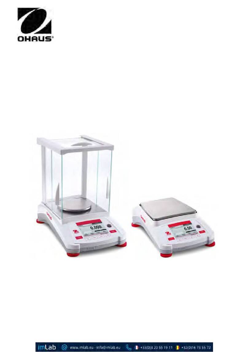
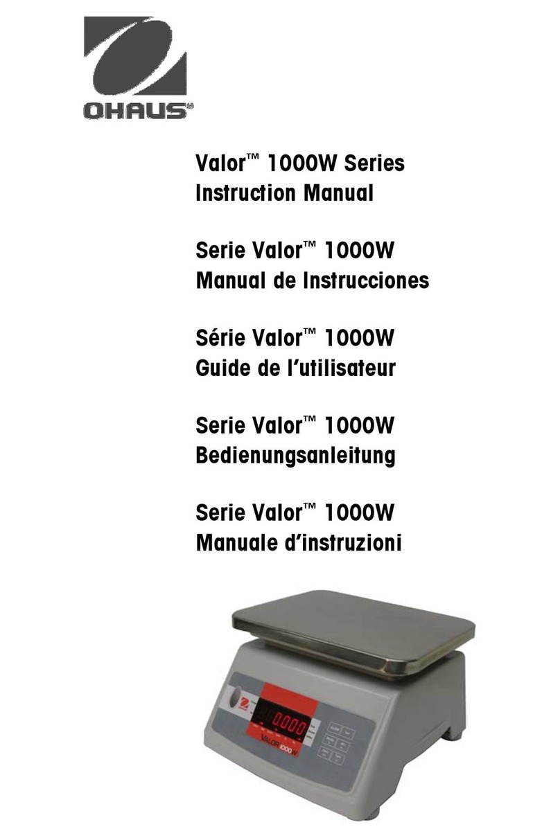
OHAUS adventurer+ User manual

Ohaus Corporation
19A Chapin Road
P.O. Box 2033
Pine Brook, NJ 07058-2033
ADVENTURER+
ANALYTICAL AND
PRECISION BALANCES
SERVICE MANUAL
Ohaus Corporation 19A Chapin Road, P.O. Box 2033, Pine Brook, NJ 07058-2033 (973) 377-9000

ADVENTURER+ Service Manual P/N 83020790 A
OhausCorporation www.ohaus.com 2
SERVICE MANUAL
Adventurer Balances
Ohaus Corporation
19A Chapin Road
P.O. Box 2033
Pine Brook, NJ 07058-2033
The information contained in this manual is believed to be accurate at the time of publication, but Ohaus
Corporation assumes no liability arising from the use or misuse of this material. Reproduction of this
material is strictly prohibited.
Material in this manual is subject to change.
© Copyright 2009 Ohaus Corporation, all rights reserved.
® Registered trademark of Ohaus Corporation.

ADVENTURER+ Service Manual P/N 83020790 A
OhausCorporation www.ohaus.com 3
OHAUS DOCUMENT NUMBER
83020790
THIS DOCUMENT CONTAINS CONFIDENTIAL AND PROPRIETARY INFORMATION OF
OHAUS CORP. THE CONTENTS HEREOF MAY NOT BE USED NOR REPRODUCED IN
WHOLE OR IN PART WITHOUT THE WRITTEN AUTHORIZATION OF OHAUS
CORPORATION. COPYRIGHT 2003 OHAUS CORPORATION
PART NUMBER
83020790
TITLE
ADVENTURER+ SERVICE MANUAL
WRITTEN BY: Gavin Cao DATE: 08/04/09 APPVD BY:
RECORD OF CHANGES
REV. DATE ECN BY DESCRIPTION
A 08/04/09 N/A NO INITIAL DRAFT

ADVENTURER+ Service Manual P/N 83020790 A
OhausCorporation www.ohaus.com 4
TABLE OF CONTENTS
1INTRODUCTION.....................................................................................................................................6
1.1 INTRODUCTION ..............................................................................................................................6
1.2 SERVICE FACILITIES......................................................................................................................6
1.3 TOOLS AND TEST EQUIPMENT REQUIRED ................................................................................7
1.3.1 Special Tools............................................................................................................................7
1.3.2 Standard Tools and Test Equipment......................................................................................7
1.4 TEST MASSES REQUIRED.............................................................................................................7
1.5 SPECIFICATIONS............................................................................................................................8
2THEORY OF OPERATION .....................................................................................................................9
2.1 BALANCE OPERATION..................................................................................................................9
2.2 OVERVIEW OF THE CONTROLS ...................................................................................................9
2.3 OVERVIEW OF THE DISPLAY INDICATORS...............................................................................10
2.4 TURNING ON THE BALANCE.......................................................................................................10
2.5 MENU SETUP ................................................................................................................................11
2.6 TRANSDUCER DESCRIPTION .....................................................................................................12
2.7 BLOCK DIAGRAM CIRCUIT DESCRIPTION................................................................................12
2.7.1 Main PC Board........................................................................................................................12
2.7.2 Cell PC Board.........................................................................................................................13
2.7.3 RS232 Board...........................................................................................................................13
3TROUBLESHOOTING..........................................................................................................................15
3.1 TROUBLESHOOTING ...................................................................................................................15
3.2 DIAGNOSTIC GUIDE.....................................................................................................................15
3.2.1 Diagnosis................................................................................................................................15
3.3 ERROR CODES .............................................................................................................................16
4MAINTENANCE PROCEDURES..........................................................................................................17
4.1 PREVENTIVE MAINTENANCE......................................................................................................17
4.1.1 Preventive Maintenance Checklist .......................................................................................17
4.2 TESTING ........................................................................................................................................17
4.2.1 Operational Test.....................................................................................................................17
Segment Display Test .........................................................................................................................17
4.2.2 Calibration ..............................................................................................................................18
4.2.3 Performance Tests - Precision and Analytical Balances ...................................................20
4.3 DISASSEMBLY/ASSEMBLY PROCEDURES...............................................................................27
4.3.1 Disassembling the Balance...................................................................................................27
4.3.2 Re-assembling the Balance ..................................................................................................28
4.4 REPLACEMENT OF MAJOR COMPONENTS..............................................................................29
4.4.1 Transducer Removal - Precision ..........................................................................................29
4.4.2 Transducer Disassembly/Cleaning/Alignment - Precision ................................................29
4.4.3 Transducer Removal - Analytical .........................................................................................34
4.4.4 Main Printed Circuit Board (PCB) Replacement - Precision and Analytical Balances....36
4.4.5 RS232 Printed Circuit Board Replacement - Precision and Analytical Balances............36
4.4.6 Membrane Switch Replacement - Precision and Analytical Balances..............................36
5AR Series Service Tool.......................................................................................................................38
5.1 Run ARServiceToolDealer.exe ....................................................................................................38

ADVENTURER+ Service Manual P/N 83020790 A
OhausCorporation www.ohaus.com 5
5.2 Open COM PORT setting window................................................................................................39
5.3 Restore EEPROM Function..........................................................................................................40
5.4 Replace Loadcell Function ..........................................................................................................40
5.5 Replace PCB Function .................................................................................................................41
5.6 Download Software.......................................................................................................................41
5.7 Diagnostic Function .....................................................................................................................42
6DRAWINGS AND PARTS LISTS .........................................................................................................43
6.1 DRAWINGS....................................................................................................................................43

ADVENTURER+ Service Manual P/N 83020790 A
OhausCorporation www.ohaus.com 6
1 INTRODUCTION
1.1 INTRODUCTION
This service manual contains the information needed to perform routine maintenance and service on the Ohaus
Adventurer+ Analytical and Precision balances. Balances are rated from 65 grams to 4200 grams capacity.
The content of this manual is contained in five chapters.
Chapter 1 Introduction - Contains information regarding service facilities, tools and test equipment,
measuring masses, and specifications.
Chapter 2 Theory of Operation - Contains information on the mechanical and electronic functions of the
balance.
Chapter 3 Troubleshooting - Contains a diagnosis/diagnostics chart and error code table.
Chapter 4 Maintenance Procedures - Contains preventive maintenance procedures, performance tests
and adjustments, disassembly/replacement procedures, and calibration procedures.
Chapter 5 AR Series Service Tool – Describe how to use the service tool.
Chapter 6 Drawings and Parts Lists - Contains exploded views of Adventurer balances and Transducers
identifying all serviceable components with parts lists.
Before servicing the balance, you should be familiar with the Instruction Manual which is packed with every
balance.
1.2 SERVICE FACILITIES
To service the Ohaus Adventurer balance, the service area should meet the following requirements:
DO NOT SERVICE the balance:
Next to open windows or doors causing drafts or rapid temperature changes.
Near air conditioning or heat vents.
Near vibrating, rotating or reciprocating equipment.
Near magnetic fields or equipment that generates magnetic fields.
On an unlevel work surface.
Allow sufficient space around the instrument for ease of operation and keep away from radiating heat
sources.

ADVENTURER+ Service Manual P/N 83020790 A
OhausCorporation www.ohaus.com 7
1.3 TOOLS AND TEST EQUIPMENT REQUIRED
In order to properly service the Ohaus Adventurer balances, certain Ohaus special tools and test items are
required in addition to standard electronic tool kits. These items are listed as follows:
1.3.1 Special Tools
1. Test Fixture P/N 923345 for use with Models AR153, AR223, AR323, AR423, AR423D..
2. Test Fixture P/N 923389 for use with Models AR522, AR1502, AR2202, AR3202, AR4202, AR4202D,
AR4201.
3. Test Fixture P/N 476001-02 for use with Models AR64, AR124, AR224.
1.3.2 Standard Tools and Test Equipment
1. Digital Voltmeter (DVM) - Input impedance of at least 10 megohms in the 1 Volt dc position.
2. Nut driver, 6mm
3. Hex or Allen key wrenches, metric.
4. Other assorted hand tools, tweezers, adjustable open wrenches, etc.
5. Soldering iron (50 watt) and solder (rosin core solder, not acid core).
6. Solder remover.
1.4 TEST MASSES REQUIRED
The masses required to test the Ohaus Adventurer balances must meet the requirements of ASTM Class 1
Tolerance. The mass values are listed in Table 1-1.
TABLE 1-1 MASS VALUES
CAPACITY LINEARITY
MASSES
SPAN
ONLY
MASSES
65g 25g/50g 50g
120g 50g/100g 100g
220g 100g/200g 200g
150g 75g/150g 150g
320g 150g/300g 300g
420g 200g/400g 400g
420g/100g 200g/400g 400g
520g 250g/500g 500g
1500g 750g/1500g 1500g
2200g 1000g/2000g 2000g
3200g 1500g/3000g 3000g
4100g 2000g/4000g 4000g
4200g/1000g 2000g/4000g 4000g

ADVENTURER+ Service Manual P/N 83020790 A
OhausCorporation www.ohaus.com 8
1.5 SPECIFICATIONS
Complete specification for the Ohaus adventurer balances are listed in Table 1-2. When a balance has been
serviced, it must meet the specifications listed in the table. Before servicing the balance, determine what
specifications are not met.
TABLE 1-2. ADVENTURER SPECIFICATIONS
Capacity (g) 65 120 220 150 220 320 420 420/100
520 1500 2200 3200 4200 4200/100
4200
Readability 0.1mg 0.001g
0.01/
0.001g 0.01g 0.1/
0.01g 0.1g
Weighing units/modes g, kg, mg, ct, lb, oz, gn, dwt, percent, Parts Counting
Repeatability (Std. Dev.) 0.1mg 0.001g 0.01/
0.001g 0.01g 0.1/
0.01g 0.1g
Linearity ±0.2mg ±0.3mg ±0.002g 0.003g
±0.01
/0.001g
0.01g
±0.02g ±0.03g
0.1/
0.01g ±0.1g
Tare Range Full capacity by subtraction
Stabilization Time (s) 4s 3s 2s
Sensitivity Drift 4ppm/°C 10ppm/°C
Operating Temp Range 50° to 86° F/10° to 30° C
Power Requirements 8.5 - 14.5V 50/60Hz 4VA or 8.5 - 20V 4W
Calibration 60g 100g 200g 150g 200g 300g
400g 400g 500g
1500g
2000g 3000g 4000g
Pan Size (in/cm) 3.5/9 dia. 3.9/10 dia. 7.1/18 dia.
Draft shield clearance
height above pan (in/cm) 9.3/23.6 6.8/17.25 ---
Dimensions (WxHxD) (cm) 36.6x11x34.3 21.7x21x34.3 21.7x11x34.3
Net Wt (lb/kg) 10.5/4.8 10/4.5 8.5/3.9
Shipping Wt (lb/kg) 17/7.8 16/7.3 14/6.4
Item No. AR
64
AR
124
AR
224
AR
153
AR
223
AR
323
AR
423
AR
423D
AR
522
AR
1502
AR
2202
AR
3202
AR
4202
AR
4202D
AR
4201
Admissible ambient conditions
Use only in closed rooms
Temperature range: 50°F to 86°F / 10°C to 30°C
Atmospheric humidity: 80% rh @ to 30°C
Voltage fluctuations: -15% +10%
Installation category: II
Pollution degree: 2
Power supply voltage: 8.5-14.5V ac, 50/60 Hz, 4VA or 8.5-20V dc, 4W
Power Adapter: 12104881, 220V/50Hz

ADVENTURER+ Service Manual P/N 83020790 A
OhausCorporation www.ohaus.com 9
2 THEORY OF OPERATION
2.1 BALANCE OPERATION
This chapter contains information on the basic operation of the balance, mechanical descriptions of the
Transducers and a block diagram description of the circuitry.
Exploded view drawings are included in chapter 5 which identifies all mechanical components of the balance. The
descriptions in this manual refer to the name of the components identified on the exploded view drawing with the
numbered callout.
With power applied, press , all segments will appear briefly followed by a software revision number (when
plugged in first time) or after a power interruption and then * 0.00g. Allow 20 minutes warm-up time. When the
balance is first turned on, it can be used to weigh in grams or tare items without setting the menus.
2.2 OVERVIEW OF THE CONTROLS
No. Button Function and Description
1
Short press->Power on /Zero/ Confirm and next to sub-menu
Long press->Power off
2
Short press->Print result /Next to sub-menu
Long press->Switch Unit
3
Short press->Selected menu in main-menu
Hold press->Change to other weighing mode
Hold press->Set present mode parameter
4
Short press->Tare/Exit to menu
Long press->Go into Cal menu/Select other menu

ADVENTURER+ Service Manual P/N 83020790 A
OhausCorporation www.ohaus.com 10
5 Leveling
indicator Indicates leveling position of the balance
6 Leveling feet Used to level the balance
2.3 OVERVIEW OF THE DISPLAY INDICATORS
No. Function Description
1 Main Display(7 Segment)
2 [] Reduce digital result (only for LFT model)
3 Unit
4 MEM
5 PC(PIECE)
6 auxiliary(14 bit)
7 Gross
8 Brutto
9 Tare
10 Pre-set Brutto
11 NET weighing
12 Stable mark
13 Negative symbols
14 Zero symbols
2.4 TURNING ON THE BALANCE
The Adventure balance is ready to operate. When the balance is first turned on and it completes its checks, it can
be used to weigh or tare materials without setting the menus. It is recommended that you calibrate the balance
before use.
Power ON
Press , all segments will appear briefly followed by a software revision number (when plugged in first time)
or after a power interruption and then * 0.00g. Allow 20 minutes warm-up time. When the balance is first turned on,

ADVENTURER+ Service Manual P/N 83020790 A
OhausCorporation www.ohaus.com 11
it can be used to weigh in grams or tare items without setting the menus.
Power OFF
To turn the balance OFF, press and hold until the display indicates OFF then release.
2.5 MENU SETUP
Programmable features of the Adventurer balances are contained in menus which are accessed through the front
panel control switches. Figure 2-1 illustrates how the menus are structured. The Adventurer balances must be
properly set in order for test results to be valid.
The setup menu permits you to activate available weighing units, parts counting, linearity calibration, keystroke
tone and print parameters. To enter the menu, press and hold . To advance through the menus,
press . To enter a selected menu, press . After you make selections in any menu, you may
continue to make additional changes in other menus before exiting and saving. To exit a menu and return to
weigh mode, press .
Figure 2-1 Balance Menus

ADVENTURER+ Service Manual P/N 83020790 A
OhausCorporation www.ohaus.com 12
2.6 TRANSDUCER DESCRIPTION
Figure 2-2 illustrates a typical Transducer used in the Adventurer balances. The Transducer is attached to the
case of the balance. The force of a weight placed on the weighing Pan is exerted on the Hanger which is guided
by the Upper and Lower Flexure Arms. The Load Flexure transfers the force vertically to the Ratio Beam. The
Ratio Flexures form a pivot for the Ratio Beam.
Any mass placed on the Pan applies a downward force to the Load Flexure by means of the Center Post. The
Load Flexure pulls down on the front end of the Ratio Beam which pivots, pulling the Force Coil up into the air gap
of the Magnet. The upward movement of the Vane (which is connected to the Ratio Beam) is detected by the
Position Sensor. The Position Sensor contains one light emitting diode (LED) and two photo resistors. When the
Vane moves, the amount of light is varied, causing one of the photo resistors to change its resistance value. The
resultant signal goes into an amplifier to be amplified and filtered. The signal then goes through a current amplifier,
then fed to the force coil which interacts with the Magnet returning the Ratio Beam to the null position. In the null
position, light should strike each photo resistor equally. The entire process takes approximately 4 seconds from
the time any mass is placed on the Pan to achieve a stable reading.
The mechanical zero of the system is moved to the approximate middle of the measuring range by the Counter
Weight. Displacement of the Position Sensor Vane from the normal position results in a current change in the
Force Coils. The Force Coils are located in the field of the permanent Magnets which are mounted on the
Transducer Base. This means that with a 50% load on the Pan, the Ratio Beam is in equilibrium and the sum of
the forces from the Force Coils is zero. The temperature sensitivity of the Permanent magnets is compensated in
the electronics by a Temperature Sensor which is physically mounted on the magnet assembly.
Figure 2-2 Transducer Assembly
2.7 BLOCK DIAGRAM CIRCUIT DESCRIPTION
Figure 2-3 illustrates the Adventurer electronic circuitry as a block diagram.
2.7.1 Main PC Board
Power Supply
Power is supplied to the balance through an AC/AC adapter which provides 12 Volts ac or DC/DC adapter which

ADVENTURER+ Service Manual P/N 83020790 A
OhausCorporation www.ohaus.com 13
provides 12Volts dc. The main PC board contains a diode bridge and 4 voltage regulators which provide
regulated voltages. The 3.3 Volts is provided to the digital circuitry and the 10 Volts dc and -12 Volts are for
operating the balance, and 5 Volts is for backlit.
MELSI2
MELSI2 is a digital integrated circuit that contains the digital circuitry needed to operate a two-channel charge
balance deltasigma A/D converter.
Microprocessing Unit
The LPC2138 microcontrollers is based on a 32/16 bit ARM7TDMI-S™ CPU with real-time emulation and
embedded trace support, that combines the microcontroller with 512 kB of embedded high speed Flash memory.
A 128-bit wide memory interface and an unique accelerator architecture enable 32-bit code execution at
maximum clock rate.
RTC unit
The LPC2138 include the RTC function. A rechargeable circuitry is designed for the RTC as power supply.
Parameter Storage
The EEPROM is a 2048 x 8 bit electrically erasable and programmable memory which stores some information of
production.
2.7.2 Cell PC Board
Reference voltage
The cell PC board contains a reference voltage which is used for producing a constant current source.
Constant current driver circuitry
The two switches are transfer switches for the constant current to the two force coils to compensate the
measured weight.
Weight Measurement
The position sensor supplies an electrical current, the magnitude of which depends of the position of the sensor
vane, to the PID controller after the current being amplified and converted to voltage. The output signal of the PID
controller is compared with a periodic ramp signal. The output signal of the comparator is a pulse signal which is
passed to the microprocessing unit as the weighing results.
Temperature Measurement
A thermistor is mounted in the transducer as a temperature sensor. The switched temperature dependent current
charges and discharges the integrator. The output voltage of the integrator is compared with a dc voltage. The
output signal of the comparator is a pulse signal which is passed to the micro controller as the temperature results
and it is used to compensate the weighing result in the microprocessing unit.
Parameter Storage
The EEPROM is a 2048 x 8 bit electrically erasable and programmable memory which stores resettable
parameters such as the temperature compensations coefficient, unit, scaling factor etc.
2.7.3 RS232 Board
The data I/O operation is controlled by the UART unit which is integrated in the micro controller. Signals RXD,

ADVENTURER+ Service Manual P/N 83020790 A
OhausCorporation www.ohaus.com 14
TXD, DTR and DSR are provided and go to a driver/receiver IC located on the RS232 board.
Figure 2-3 Adventurer Balance Block Diagram

ADVENTURER+ Service Manual P/N 83020790 A
OhausCorporation www.ohaus.com 15
3 TROUBLESHOOTING
3.1 TROUBLESHOOTING
This section of the manual specifies problem areas of the balance which can occur. information is contained to
isolate specific problems using Table 3-1, Diagnostic Guide, and Table 3-2, Error Codes. Follow all directions
step by step. Make certain that the work area is clean and use care when handling components of the balance.
3.2 DIAGNOSTIC GUIDE
Table 3-1 is a diagnostic guide designed to help locate the problem area quickly and easily. To use the table, first
locate the symptom that you are observing. Follow the symptom column and review the probable cause column
and remedy column. The probable causes are listed with the most common cause first. If the first remedy does
not fix the problem, proceed on to the next remedy. Before attempting to repair the balance, read all chapters of
this manual to familiarize yourself with the balance components and operation. Do not attempt repairs unless you
fully understand the operation of the balance.
3.2.1 Diagnosis
1. Isolate and identify the symptom.
2. Refer to Table 3-1 Diagnostic guide and locate the symptom.
3. Follow the suggested remedies in the order that they appear.
4. Perform the indicated checks, or see the appropriate section of the manual.
5. Repair or replace the defective section of the balance.
NOTE:
If more than one symptom is observed, it is necessary to approach one
area at a time, and also remember that the symptoms may be interrelated.
In the event that erratic or fluctuating weight readings are observed, it is necessary to isolate the problem to either
the mechanical area or the electronic area of the balance.
If a problem arises that is not covered in this manual, contact:
Ohaus Corporation
19A Chapin Road
P.O. Box 2033
Pine Brook, NJ 07058-2033 USA
Tel: 973-377-9000
Fax: 973-593-0359
In the United States call toll free, 800-526-0659 between 8:00 a.m. and 6:00 p.m. EST.
TABLE 3-1 DIAGNOSTIC GUIDE

ADVENTURER+ Service Manual P/N 83020790 A
OhausCorporation www.ohaus.com 16
3.3 ERROR CODES
This balance is equipped with software which will display an error condition when it occurs. When a problem
occurs using the balance, the display will indicate an error code. Review the listed codes and follow instructions to
correct the problem. Table 3-2 Error Codes, describes the various error codes which can appear on the display
and specifies the probable reason and remedy.
TABLE 3-2 ERROR CODES
Error
Codes Possible Cause Remedy
Error 7.0 Unstable weight reading when defining the
reference weight. Eliminate vibration.
Error 8.1 Weight reading exceeds Power On Zero
limit Clear platform.
Error 8.2 Weight reading below Power On Zero limit. Put platform on balance.
Error 8.3 Weight reading exceeds overload limit. Clear platform.
Error 8.4 Weight reading below underload limit. Put platform on balance.
Error 9.5 Calibration information is error Send the balance back to Ohaus and repaired.
Error 5.3 Can not read EEPROM datum on loadcell. Repeat to connect or disconnect power.
If can't be remedy, send back to Ohaus.
SYSPTOM PROBABLE CAUSE REMEDY
No Display Power Adapter not connected. Connect Adapter.
Incorrect weight reading.
Balance out of calibration.
Balance was not rezeroed before
weighing.
Calibrate the balance. Press
with no weight on the
pan, then weigh item.
Calibration procedure does not
work.
Incorrect calibration masses being
used. Use correct masses.
Unable to display weight in a
particular weighing unit. Weighing unit not activated in menu. Use Units menu to set desired
units ON (see menu).
Balance won't store selections
made in menu.
YES selection was not used before
exit menu.
You must use YES and then exit
each menu and save selections.

ADVENTURER+ Service Manual P/N 83020790 A
OhausCorporation www.ohaus.com 17
4 MAINTENANCE PROCEDURES
4.1 PREVENTIVE MAINTENANCE
Ohaus balances are precision instruments and should be carefully handled, stored in a clean dry area which is
dust free, and cleaned periodically. It is recommended that when a balance has had chemicals or liquids spilled
on it, the balance should be cleaned as soon as possible. Use warm water on a damp cloth to clean all exterior
surfaces. Do not leave a mass on the balance when the balance is not in use. When moving the balance from a
storage area which is at a different temperature than the area where the balance is to be operated, allow sufficient
time for the balance mechanism to temperature stabilize. This time can vary quite a bit depending upon the
temperature differences. Allow one (1) hour for each 5 degrees Fahrenheit temperature change before using the
balance. Also, after turning the balance ON, allow one hour after temperature stabilization for the balance
electronics to stabilize.
4.1.1 Preventive Maintenance Checklist
On a regular basis, the balance should be inspected and checked as follows:
1. Remove the Platform and Sub Platform (on 4kg balances) and inspect and clean the area beneath the
Platform.
2. Clean the outside of the balance using a damp cloth with water.
CAUTION
DO NOT USE CHEMICAL CLEANERS OR SOLVENTS OF ANY TYPE.
SOME CLEANERS ARE ABRASIVE AND MAY AFFECT THE FINISH OF
THE BALANCE.
3. Check the Power Cord for broken or damaged insulation.
4. Make a visual inspection for faulty connectors, wiring, and loose hardware.
4.2 TESTING
Before servicing the Adventurer balance, an operational test and various performance tests should be made to
ascertain whether or not the balance meets specifications. Turn the balance on and allow it warm up for at least
one hour before performing these tests. Make sure the test area is free from drafts and the surface that the
balance rests on is level and vibration free. The masses used for the performance tests and adjustments must
meet or exceed ASTM Class 1 Tolerance.
4.2.1 Operational Test
1. Connect a functioning Power Adapter to the balance power receptacle assembly located at the rear of the
balance.
2. Plug the Power Cord into a suitable power source.
Segment Display Test
Turn the balance on, all segments are enabled and displayed breifly, then the model number of the balance
followed by a software revision number. This is a segment display test. Figure 4-1 is a full display test.

ADVENTURER+ Service Manual P/N 83020790 A
OhausCorporation www.ohaus.com 18
Figure 4-1 Segment Display
4.2.2 Calibration
To verify that the Balance is functioning properly, it must be calibrated prior to testing. At this point, the Balance
should have the menus set up if functional. After calibration, proceed to Performance Tests, paragraph 4.2.3 for
Precision balances and paragraph 4.2.4 for Analytical balances.
Calibration can be affected by changes in location, temperature, or rough handling. AdventurerTM balances can
be calibrated in two ways: Span calibration or Linearity calibration. Span calibration resets the balance's weighing
range using two weight values: zero and a weight value at or near the balance's capacity. Linearity calibration
minimizes deviation between actual and displayed weights within the balance's weighing range. Three weight
values are used: zero, a weight value within the balance's weighing range and a weight value at or near the
balance's specified capacity.
4.2.2.1 Calibration Masses
Before beginning calibration, make sure masses are available. If you begin calibration and realize calibration
masses are not available, exit the menu. The balance will retain previously stored calibration data. Calibration
should be performed as necessary to ensure accurate weighing. Masses required to perform the procedures are
listed in Table 4-1.
TABLE 4-1 CALIBRATION MASSES
Model Capacity Span Masses Linearity Masses
AR64 65 50 25/50
AR124 120 100 50/100
AR224 220 200 100/200
AR153 151 150 75/150
AR223 220 200 100/200
AR323 320 300 150/300
AR423 420 400 200/400
100 -- --
AR423D 420 400 200/400
AR522 520 500 250/500
AR1502 1520 1500 750/1500
AR2202 2200 2000 1000/2000
AR3202 3200 3000 1500/3000
AR4202 4200 4000 2000/4000
1000 -- --
AR4202D 4200 4000 2000/4000
AR4201CN 4200 4000 2000/4000

ADVENTURER+ Service Manual P/N 83020790 A
OhausCorporation www.ohaus.com 19
4.2.2.2 Span Calibration
1. With the balance turned ON, press and hold until MENU is displayed in the LCD main area
(CALIBRATION is display in auxiliary area). Then release the switch.
2. Press , CAL is displayed in the main area (SPAN is displayed in auxiliary area), then press
again, --0-- momentarily displayed in main area (BUSY is display in auxiliary area).
Do not disturb the balance when –0-- is displayed. Incorrect calibration may result.
3. After several seconds, the value of span calibration mass is displayed in the main area (ADD WEIGHT is
displayed in the auxiliary area). Place the indicated mass on the pan. BUSY is displayed and flickered in the
auxiliary area.
4. After several seconds, --0-- is displayed in the main area (CLEANPAN is displayed in the auxiliary area). It
means remove the mass.
5. Remove the calibration mass from the pan. BUSY is momentarily displayed and CAL DONE is displayed in
the auxiliary area. Then the balance returns to the weighing mode.
4.2.2.3 Linearity Calibration
1. With the balance turned ON, press and hold until MENU is displayed in the LCD main area
(CALIBRATION is display in auxiliary area). Then release the switch.
2. Press , CAL is displayed in the main area (SPAN is displayed in auxiliary area), then
press , LINEAR is display in auxiliary area. Press to enter linearity calibration.
2. --0-- momentarily displayed in main area (BUSY is display in auxiliary area). Then the value of span
calibration mass is displayed in the main area (PUT WEIGHT is displayed in the auxiliary area). Place the
indicated mass on the pan. --0-- is displayed in the main area (CLEAN PAN is displayed in the auxiliary area).
3. Remove the mass from the pan. BUSY is displayed in the auxiliary area.
4. The value of the first linearity calibration mass is displayed in the main area (PUT WEIGHT is displayed in
the auxiliary area). Place the indicated mass on the pan. BUSY is displayed in the auxiliary area.
5. The value of the second linearity calibration mass is displayed in the main area (PUT WEIGHT is displayed
in the auxiliary area). Redo step 4 until the maxim linearity calibration mass is placed on the pan.
6. The value displayed in the main area is descended. Remove the mass to match the indicated value. Redo
this step until --0-- is displayed in the main area (CLEAN PAN is displayed in auxiliary area).
The first mass placed is first removed.
7. Remove the mass from the pan. BUSY is momentarily displayed and LIN DONE is displayed in the
auxiliary area. Then the balance returns to the weighing mode.

ADVENTURER+ Service Manual P/N 83020790 A
OhausCorporation www.ohaus.com 20
4.2.3 Performance Tests - Precision and Analytical Balances
Accurate performance of the Adventurer precision balance is determined by a series of four performance tests.
The displayed readings are compared with the tolerances listed in Tables 4-2 and 4-3. Tolerance values are
expressed in counts. A one count change is equal to the last digit shown on the balance display.
TABLE 4-2 TOLERANCES PRECISION
TOLERANCE - COUNTS PRECISIONPERFORMANCE
TEST AR153 AR223
AR323 AR423 AR423D
AR522
AR1502
AR2202
AR3202 AR4202 AR4202D
AR4201
Precision
(mg) ±1 ±1 ±1 ±1 ±10/1 ±10 ±10 ±10 ±10 ±10 ±100/10
±100
OffCenterLoad
(mg) ±3 ±3 ±3 ±3 ±3 ±30 ±30 ±30 ±30 ±30 ±100 ±100
CenteredLoad
(mg) ±2 ±2 ±2 ±2 ±10/1 ±20 ±20 ±20 ±20 ±20 ±100/10
±100
Repeatability
(mg) ±1 ±1 ±1 ±1 ±10/1 ±10 ±10 ±10 ±10 ±10 ±100/10
±100
TABLE 4-3 TOLERANCES ANALYTICAL
TOLERANCE - COUNTS ANALYTICALPERFORMANCE
TEST AR64 AR124 AR224
Precision(mg) ±0.1 ±0.1 ±0.1
OffCenterLoad(mg) ±0.5 ±0.5 ±0.5
CenteredLoad(mg) ±0.2 ±0.2 ±0.3
Repeatability(mg) ±0.1 ±0.1 ±0.1
The following performance tests are used to evaluate the balance operation before and after repairs. Each
balance tested must meet the requirements specified in each test as well as the specifications listed in Table 1-2
depending upon the model. Before proceeding with the following tests, all the procedures starting with paragraph
4.2 must have been accomplished on the Balance first.
4.2.3.1 Precision Test - Precision and Analytical Balances
Precision is a word used in balance specifications meaning the Standard Deviation of a set of similar weight
readings. To determine whether a balance meets the calculated Standard Deviation value listed in the Tolerance
Tables 4-2 and 4-3, perform the following test:
Test
1. Tare the balance. The reading on the display should be 0g.
2. Select a mass weighing near the maximum capacity of the balance and place the mass on the center of the
Platform observe and record the reading.
3. Remove the mass. Reading should return to 0g ± 1 count.
4. Repeat this test for three times. Reading should be within ±1 count of the reading recorded. If the reading is
less than ±1 count, the balance passes the Precision Test. If the deviation for a set of readings is more than
±1 count, proceed to the next step.
5. If the deviation for any set of readings (using the same mass placed on the center of the Platform) is
greater than the tolerance listed in Table 4-2, the balance does not meet the precision specification. Inspect
and correct the following areas:
5A. Check for mechanical obstructions. Any foreign object touching any part of the moving assemblies will
cause a balance to fail the Precision Test. Inspect and correct as necessary.
Table of contents
Other OHAUS Scale manuals

OHAUS
OHAUS EXPLORER User manual

OHAUS
OHAUS SD35 User manual

OHAUS
OHAUS BW Series User manual

OHAUS
OHAUS Valor V71P1502T User manual

OHAUS
OHAUS SHRK07AL1 User manual

OHAUS
OHAUS Navigator NV212 User manual

OHAUS
OHAUS CS 200 User manual

OHAUS
OHAUS Defender D12RQR User manual

OHAUS
OHAUS Defender 3000 Series User manual

OHAUS
OHAUS Navigator Series User manual

OHAUS
OHAUS Valor 1000 User manual

OHAUS
OHAUS Emerald Series User manual

OHAUS
OHAUS TA152 User manual

OHAUS
OHAUS Harvard Junior User manual

OHAUS
OHAUS Scout SJX User manual

OHAUS
OHAUS ES6R User manual

OHAUS
OHAUS Scout SPX123 User manual

OHAUS
OHAUS Skipper 5000 User manual

OHAUS
OHAUS PX Series User manual

OHAUS
OHAUS Courier 1000 User manual