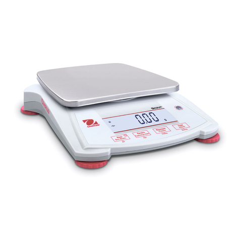
OHAUS Pioneer PA64 User manual

SERVICE MANUAL
Ohaus Corporation 19A Chapin Road, P.O. Box 2033, Pine Brook, NJ 07058-2033 (973) 377-9000


TABLE OF CONTENTS
Ohaus Corporation www.ohaus.com i Pioneer™ Balances Service Manual
Page No.
CHAPTER 1 GETTING STARTED
1.1 Introduction..............................................................................................................1-1
1.2 Service Facilities......................................................................................................1-1
1.3 Tools and Test Equipment Required........................................................................1-2
1.3.1 Special Tools....................................................................................................1-2
1.3.2 Standard Tools and Test Equipment.................................................................1-2
1.4 Specifications...........................................................................................................1-2
1.5 Balance Operation ...................................................................................................1-5
1.5.1 Overview of the Controls...................................................................................1-5
1.5.2 Overview of the Display Indicators....................................................................1-6
1.5.3 Power On..........................................................................................................1-7
1.5.4 Power Off..........................................................................................................1-7
1.5.5 Menu Setup ......................................................................................................1-7
1.5.6 Menu Structure.................................................................................................1-7
1.5.7 The Load Cell ...................................................................................................1-8
1.6 Connecting the RS232 Interface ..............................................................................1-9
1.7 RS232 Commands.................................................................................................1-10
CHAPTER 2 TROUBLESHOOTING
2.1 Troubleshooting.......................................................................................................2-1
2.1.1 General Procedures for Troubleshooting ..........................................................2-1
2.2 Diagnostic Guide......................................................................................................2-1
2.2.1 Diagnosis..........................................................................................................2-1
2.3 Error Codes..............................................................................................................2-4
CHAPTER 3 MAINTENANCE PROCEDURES
3.1 Preventive Maintenance...........................................................................................3-1
3.1.1 Preventive Maintenance Checklist....................................................................3-1
3.2 Opening the Balance................................................................................................3-1
3.2.1 Variations in Opening Pioneer Models..............................................................3-2
3.3 Load Cell Removal and Disassembly.......................................................................3-3
3.3.1 Variations in Pioneer Load Cells.......................................................................3-3
3.3.2 Disassembly of Precision Balances with Internal Calibration.............................3-4
3.3.3 Removing Internal Calibration Weights.............................................................3-5
3.3.4 Servicing the Internal Calibration Mechanism ...................................................3-5
3.3.5 Reassembling the Internal Calibration Mechanism............................................3-6
3.3.6 Disassembly of Precision Balances with InCal Mechanism...............................3-6
3.3.7 Removing the Load Cell –Precision Balances..................................................3-7
3.3.8 Load Cell Disassembly –Precision Balances....................................................3-8
3.3.9 Position Sensor Board Removal/Replacement/Adjustment –Precision...........3-13
3.3.10 Main Printed Circuit Board (PCB) Replacement –All Balances.......................3-14
3.3.11 Load Cell Reassembly –Precision Balances..................................................3-15
3.3.12 Removing the InCal Mechanism from InCal Analytical Balances.....................3-19
3.3.13 Removing Internal Calibration Weights and Components ...............................3-19
3.3.14 Re-Installing Internal Calibration Components................................................3-21
3.3.15 Load Cell Removal/Installation –Analytical Balances.....................................3-21
3.3.16 Disassembling Analytical Load Cells...............................................................3-22
3.3.17 Position Sensor PC Board Removal/Replacement/Adjustment - Analytical.....3-28
3.3.18 Reassembling Analytical Load Cells ...............................................................3-29
3.3.19 Block Style Load Cell Removal & Replacement..............................................3-34

TABLE OF CONTENTS
Pioneer™Balances Service Manual ii Ohaus Corporation www.ohaus.com
Page No.
3.3.20 Block Style Load Cell Disassembly & Replacement with Load Cell Kit............3-35
3.3.21 Progressive Disassembly of Block Style Load Cells........................................3-35
3.3.22 Internal Calibration Testing.............................................................................3-36
3.3.23 InCal Motor Removal & Replacement.............................................................3-36
3.3.24 InCal Mechanism Removal .............................................................................3-37
3.3.25 InCal Mechanism Installation ..........................................................................3-38
3.3.26 Position Sensor Assembly Removal/Installation on MFR Load Cell ................3-39
3.3.27 Removing the Block Style Load Cell from the Base Plate ...............................3-40
3.3.28 Installing the Block Style Load Cell on the Base Plate ....................................3-41
3.3.29 Removal and Installation of the Block Style Load Cell PC Board ....................3-42
3.3.30 Removing the Ratio Beam on Block Style Load Cells.....................................3-43
3.3.31 Installing the Ratio Beam on Block Style Load Cells.......................................3-47
3.3.32 Installing the InCal Weight Arm.......................................................................3-49
3.3.33 Installing the Load Cell PCB-Temperature Sensor-Position Sensor................3-51
3.2.34 Setting the Up/Down Stop Screw on Block Style Load Cells...........................3-53
CHAPTER 4 TESTING
4.1. Testing.....................................................................................................................4-1
4.1.1 Test Masses Required......................................................................................4-2
4.2 Operational Test ......................................................................................................4-1
4.3 Segment Display Test..............................................................................................4-1
4.4. Performance Tests...................................................................................................4-2
4.4.1 Precision Test...................................................................................................4-2
4.4.2 Off-Center Load Test........................................................................................4-3
4.4.3 Off-Center Load Adjustment for Precision Models.............................................4-4
4.4.4 Off-Center Load Adjustment for Analytical Models............................................4-5
4.4.5 Off-Center Load Adjustment for Block Style Models..........................................4-6
4.4.6 Repeatability Test.............................................................................................4-7
4.4.7 Linearity Test....................................................................................................4-9
CHAPTER 5 DRAWINGS AND PARTS LISTS
5-1 Precision Top Load Balance Housing & Internal Parts.............................................5-2
5-2 Round Pan Block Style InCal Balance: Housing & Internal Parts .............................5-4
5-3 Square Pan Block Style Square Pan Balance: Housing & Internal Parts..................5-6
5.4 Precision Draft Shield Balance with Draft Shield: Housing & Parts...........................5-8
5.5 Analytical Balance: Housing & Internal Parts..........................................................5-10
5.6 Precision Balance Load Cell & Parts......................................................................5-12
5.7 Analytical Balance Load Cell & Parts.....................................................................5-14
5.8 Block Style InCal Load Cell & Parts .......................................................................5-26
Appendix A STANDARD CALIBRATION
A.1 Calibration...............................................................................................................A-1
A.1.1 Calibration Masses ..........................................................................................A-1
A.2 Span Calibration .....................................................................................................A-1
A.3 Linearity Calibration ................................................................................................A-2
Appendix B SERVICE CALIBRATION
B.1 Entering the Service Menu......................................................................................B-1
B.2 Ramp......................................................................................................................B-1
B.3 Service Span Calibration.........................................................................................B-2
B.4 Service 3 Point- Linearity Calibration ......................................................................B-3

TABLE OF CONTENTS
Ohaus Corporation www.ohaus.com iii Pioneer™ Balances Service Manual
B.5 Service 5 Point- Linearity Calibration …………………………………………………...B-4
Page No.
LIST OF TABLES
TABLE NO. TITLE Page No.
1-1 Specifications: External Calibration Models (includes M Models).........................1-2
1-2 Specifications: Internal Calibration Models (C & CM)...........................................1-3
1-3 Specifications: Carat Models ...............................................................................1-3
1-4 Specifications: Gold Models (External Calibration)...............................................1-4
1-5 Specifications: Gold Models (Internal Calibration)................................................1-4
1-6 Admissible Ambient Conditions............................................................................1-5
1-7 Functions of Display Controls ..............................................................................1-5
1-8 Display Indicators ................................................................................................1-6
1-9 COM 1 Interface Pin Connections........................................................................1-9
1-10 RS232 Command Table ....................................................................................1-10
2-1 Diagnostic Guide.................................................................................................2-2
2-2 Error Codes.........................................................................................................2-4
4-1 Test Masses Required.........................................................................................4-1
4-2 Tolerances –Precision Models............................................................................4-2
4-3 Tolerances –Analytical Models ...........................................................................4-2
4-4 Repeatability Worksheet......................................................................................4-8
5-1 Precision Top Load Balance Housing & Internal Parts.........................................5-3
5-2 Round Pan Block Style InCal Balance: Housing & Internal Parts.........................5-5
5-3 Square Pan Block Style Square Pan Balance: Housing & Internal Parts..............5-7
5.4 Precision Draft Shield Balance with Draft Shield: Housing & Parts ......................5-9
5.5 Analytical Balance: Housing & Internal Parts.....................................................5-11
5.6 Precision Balance Load Cell & Parts .................................................................5-13
5.7 Analytical Balance Load Cell & Parts.................................................................5-15
5.8 Block Style InCal Load Cell & Parts...................................................................5-17
LIST OF ILLUSTRATIONS
FIGURE NO. TITLE
1-1 Pioneer, Carat and Gold Series Displays.............................................................1-5
1-2 Pioneer Display Indicators...................................................................................1-6
1-3 Pioneer Menu Structure.......................................................................................1-7
1-4 Load Cell Assembly.............................................................................................1-8
1-5 COM 1 Connector................................................................................................1-9
1-6 Soldering points J1 and J2...................................................................................1-9
3-1 Top panel lifts up and slides out...........................................................................3-2
3-2 Groove in side panel’s base liner aligns with tab on Housing...............................3-2
3-3 Precision Load Cell with Incal..............................................................................3-3
3-4 Analytical Load Cell with Incal .............................................................................3-3
3-5 Precision Load Cell..............................................................................................3-3
3-6 Analytical Load Cell.............................................................................................3-3
3-7 Precision Block Style Load Cell with InCal...........................................................3-4
FIGURE NO. TITLE Page No.
3-8 Analytical Block Style Load Cell with InCal..........................................................3-4
3-9 Precision Balance with InCal Mechanism ............................................................3-4
3-10 InCal Weight Cover removed...............................................................................3-5
3-11 Bottom Housing with Load Cell, Weight Arms and Weights removed...................3-5
3-12 InCal Motor removed from its Housing.................................................................3-6

TABLE OF CONTENTS
Pioneer™Balances Service Manual iv Ohaus Corporation www.ohaus.com
3-13 Screws securing Weight Arm assembly...............................................................3-6
3-14 Proper manner to grasp Load Cell when removing Weight Arm assembly...........3-7
3-15 Cable connects to Position Sensor Board............................................................3-7
3-16 Access the 3 screws to release Precision balance Load Cell from top center......3-7
3-17 Service Fixture, screws and washers for 150g to 310g Precision balances .........3-8
3-18 Service Fixture, screws and washers for 510g to 4100g Precision balances........3-8
3-19 Precision Load Cell top........................................................................................3-8
3-20 Precision Load Cell bottom..................................................................................3-8
3-21 Precision Load Cell (150g to 310g) top, with Service Fixture attached.................3-9
3-22 Service Fixture for 510g to 4100g Precision Load Cell, attached to Hanger.........3-9
3-23 Bent Flexure........................................................................................................3-9
3-24 Position Sensor Board.......................................................................................3-10
3-25 Contact Board with ribbon cable........................................................................3-10
3-26 Fine wires connected to the Contact Board, and affixed to Ratio Beam.............3-10
3-27 Contact Board taped to Ratio Beam after removal from frame...........................3-11
3-28 Hanger...............................................................................................................3-10
3-29 Two screws secure Magnet Half........................................................................3-11
3-30 Sideways Motion Stop Plate..............................................................................3-11
3-31 Ratio Beam clearing stop on Up/Down Stop Screw as it is lifted out..................3-12
3-32 Magnets must be clean......................................................................................3-12
3-33 Position Sensor Board.......................................................................................3-13
3-34 Adjust position of Sensor Board until Err8.X does not appear............................3-13
3-35 Position Sensor Board.......................................................................................3-14
3-36 Installing Ratio Beam, clearing the Up/down Stop Screw...................................3-15
3-37 Precision Load Cell (150g to 310g) top, with Service Fixture attached...............3-15
3-38 Service Fixture for 510g to 4100g Precision Load Cell, attached to Hanger.......3-15
3-39 Sideways Motion Stop Plate..............................................................................3-16
3-40 Two screws secure Magnet Half........................................................................3-16
3-41 Contact Board....................................................................................................3-16
3-42 Solder points on Position Sensor Board.............................................................3-16
3-43 Precision Load Cell top......................................................................................3-17
3-44 Precision Load Cell bottom................................................................................3-17
3-45 Ratio Beam Flexures and Vertical Flexure.........................................................3-17
3-46 Insert the 3 screws to secure Precision Load Cell in Bottom Housing................3-17
3-47 When Position Sensor Board shows normal weight, tighten its screws..............3-18
3-48 Analytical Balance with InCal Mechanism..........................................................3-19
3-49 InCal Weight Covers removed...........................................................................3-19
3-50 Bottom Housing with Load Cell, Weight Arms and Weights removed.................3-20
3-51 InCal Motor removed from its assembly.............................................................3-20
3-52 InCal Motor Cam in correct position for reassembly...........................................3-20
3-53 Cable connects to the Position Sensor Board....................................................3-21
3-54 On Analytical balances, the 3 screws securing Load Cell are on bottom............3-21
3-55 Service Fixture, screws and shims for Analytical balances ................................3-22
3-56 Bottom Mounting Plate and Flexure Arms, Analytical balance’s Load Cell.........3-22
3-57 Top Mounting Plate and Flexure Arms, Analytical balance’s Load Cell ..............3-22
LIST OF ILLUSTRATIONS
FIGURE NO. TITLE Page No.
3-58 Screws removed from Bottom Mounting Plate inserted into the Hanger.............3-23
3-59 Shims are inserted between the Hanger and the Load Cell ...............................3-23
3-60 Analytical balance Load Cell with Top Bracket visible........................................3-23
3-61 Vertical Flexure and screws, Lock Plate, washers, and bushings, removed.......3-23
TABLE OF CONTENTS
Ohaus Corporation www.ohaus.com v Pioneer™ Balances Service Manual
3-62 Top Flexure Arm (Analytical). ............................................................................3-23
3-63 Bottom Flexure Arm (Analytical) ........................................................................3-23
3-64 Hanger with two screws.....................................................................................3-25
3-65 Service Fixture attached to the front of Load Cell after removing Hanger ..........3-25
3-66 The Vane is secured by two screws near the rear of the Load Cell....................3-25
3-67 The Vane removed............................................................................................3-25
3-68 Two solder points on PSB, and two screw holes for removing the board...........3-26
3-69 Contact Board with 3-wire ribbon cable soldered to it ........................................3-26
3-70 Four screws secure the Magnet Half to the Ratio Beam ....................................3-26
3-71 The Magnet Half, when removed, should be cleaned ........................................3-25
3-72 A screw connects the Contact Board to the Load Cell .......................................3-26
3-73 Use a smaller screw to temporarily fasten it to the Ratio Beam..........................3-26
3-74 The Sideways Motion Stop Plate and the black Up/Down Stop screw ...............3-27
3-75 Position Sensor Board (Analytical).....................................................................3-28
3-76 Adjust Position Sensor Board vertically until Err8.X does not appear.................3-28
3-77 The Ratio Beam needs to clear the groove in the Up/Down Stop Screw............3-29
3-78 Service Fixture is installed prior to installing Ratio Beam Flexures.....................3-29
3-79 Sideways Motion Stop Plate and Up/Down Stop Screw.....................................3-29
3-80 Elongated holes on Ratio Beam Flexures go on the bottom...............................3-29
3-81 Installing the Magnet Half ..................................................................................3-30
3-82 Four screws on Magnet Half..............................................................................3-30
3-83 Position Sensor Board.......................................................................................3-30
3-84 3-wire cable soldered to Contact Board.............................................................3-30
3-85 Installing the Vane.............................................................................................3-30
3-86 Screws removed from Bottom Mounting Plate inserted into the Hanger.............3-31
3-87 Insert shims between the Hanger and the Load Cell on both sides....................3-31
3-88 Bottom Flexure Arm...........................................................................................3-31
3-89 Top Flexure Arm................................................................................................3-31
3-90 Vertical Flexure..................................................................................................3-31
3-91 Vertical Flexure and screws, Lock Plate, washers, and bushings, removed.......3-31
3-92 Analytical InCal Load Cell with Top Bracket visible............................................3-32
3-93 Analytical balance Load Cell with Top Bracket visible........................................3-32
3-94 Bottom Mounting Plate on Analytical Load Cell..................................................3-32
3-95 Ribbon cable connects PSB to Main PCB..........................................................3-32
3-96 When Position Sensor Board shows normal weight, tighten its screws..............3-33
3-97 Block Style Load Cell.........................................................................................3-34
3-98 Service Toolset for Block Style Load Cells. PN 476000-030.............................3-35
3-99 InCal Motor........................................................................................................3-36
3-100 InCal Motor Removal.........................................................................................3-36
3-101 Motor Coupler....................................................................................................3-36
3-102 Motor Shaft in counter-clockwise position..........................................................3-37
3-103 Mounting Screws holding InCal Mechanism.......................................................3-37
3-104 Removing the InCal Mechanism........................................................................3-37
3-105 InCal Mechanism Alignment..............................................................................3-38
3-106 Centering InCal Weight......................................................................................3-38
LIST OF ILLUSTRATIONS
FIGURE NO. TITLE Page No.
3-107 Removing Position Sensor.................................................................................3-39
3-108 Ratio Beam Pin Alignment.................................................................................3-39
3-109 Base Plate Removal..........................................................................................3-40
3-110 Load Cell Mounting Components.......................................................................3-41

TABLE OF CONTENTS
Pioneer™Balances Service Manual vi Ohaus Corporation www.ohaus.com
3-111 Load Cell Alignment to Base Plate.....................................................................3-41
3-112 Block Style Load Cell PC Board Item Locations.................................................3-42
3-113 Block Style Load Cell PC Board Removed from Load Cell.................................3-42
3-114 Load Cell PCB-Temperature Sensor-Position Sensor assembly........................3-43
3-115 Position Sensor .................................................................................................3-43
3-116 Removing Temperature Sensor.........................................................................3-43
3-117 Load Cell PCB...................................................................................................3-44
3-118 Contact Board Cover is removed by squeezing the plastic post.........................3-44
3-119 Contact Board with cover holder off...................................................................3-44
3-120 Centering Pins...................................................................................................3-44
3-121 Centering Pins Installed.....................................................................................3-44
3-122 Contact Board Location.....................................................................................3-45
3-123 Contact Board with cover holder off...................................................................3-45
3-124 Loosening Ratio Beam Nuts..............................................................................3-45
3-125 Ratio Beam Screws and Washers removed.......................................................3-45
3-126 Loosening InCal Weight Arm nuts......................................................................3-46
3-127 Weight Arm Screws and Washers removed.......................................................3-46
3-128 InCal Weight Arm removal.................................................................................3-46
3-129 InCal Weight Arm removed................................................................................3-46
3-130 Aluminum Sleeves removed..............................................................................3-47
3-131 Up/Down Stop Screw.........................................................................................3-47
3-132 Centering Pins removed ....................................................................................3-47
3-133 Removing the Ratio Beam.................................................................................3-47
3-134 Ratio Beam Removed........................................................................................3-47
3-135 Removing the Ratio Beam.................................................................................3-47
3-136 Ratio Beam Removed........................................................................................3-47
3-137 Removing the Aluminum Sleeves......................................................................3-47
3-138 Ratio Beam Weight Removal.............................................................................3-48
3-139 Load Cell Critical Area.......................................................................................3-48
3-140 Magnet Area......................................................................................................3-48
3-141 Ratio Beam Vane Slotted Area..........................................................................3-49
3-142 Four Ratio Beam sleeves are larger than the four Weight Arm sleeves .............3-49
3-143 Replacing the Ratio Beam.................................................................................3-49
3-144 Positioning the Ratio Beam over the Magnet.....................................................3-49
3-145 Centering Pin goes into first hole after upward bend in Ratio Beam...................3-49
3-146 InCal Weight Arm before insertion.....................................................................3-50
3-147 Inserting InCal Weight Arm................................................................................3-50
3-148 Weight Arm must be lifted slightly to insert Centering Pin..................................3-50
3-149 Proper method for tightening nuts while holding screw head stationary.............3-50
3-150 Centering pins in Ratio Beam ............................................................................3-51
3-151 Tightening Ratio Beam nuts...............................................................................3-51
3-152 Up/Down Stop Screw.........................................................................................3-51
3-153 Repositioning the Contact Board and Screw......................................................3-51
3-154 Load Cell PCB, Temperature Sensor and Position Sensor................................3-52
3-155 Groove on left of PCB fits tab on Load Cell frame..............................................3-52
LIST OF ILLUSTRATIONS
FIGURE NO. TITLE Page No.
3-156 Temperature Sensor extends into a hole in the Magnet.....................................3-52
3-157 Position Sensor on the Magnet..........................................................................3-53
3-158 Pin centered in PSB...........................................................................................3-53
3-159 Load Cell PCB Test Connector..........................................................................3-54

TABLE OF CONTENTS
Ohaus Corporation www.ohaus.com vii Pioneer™ Balances Service Manual
3-160 Test Connector Detail........................................................................................3-54
3-161 Up/Down Stop Screw.........................................................................................3-54
4-1 Segment Display .................................................................................................4-1
4-2 Mass Placement Locations for Off-Center Load Test...........................................4-3
4-3 Off-Center Load Adjustment Screws on Analytical models ..................................4-4
4-4 Off-Center Load Adjustment Screws on Precision models...................................4-4
4-5 Off-Center Load Adjustments ..............................................................................4-4
5-1 Precision Top Load Balance Housing & Internal Parts.............................................5-2
5-2 Round Pan Block Style InCal Balance: Housing & Internal Parts .............................5-4
5-3 Square Pan Block Style Square Pan Balance: Housing & Internal Parts..................5-6
5.4 Precision Draft Shield Balance with Draft Shield: Housing & Parts...........................5-8
5.5 Analytical Balance: Housing & Internal Parts..........................................................5-10
5.6 Precision Balance Load Cell & Parts......................................................................5-12
5.7 Analytical Balance Load Cell & Parts.....................................................................5-14
5.8 Block Style InCal Load Cell & Parts .......................................................................5-26
C-1 Com Port Configuration Menu.............................................................................C-1
C-2 The Software Service Tool’s Restore EEProm Tab.............................................C-2
C-3 The Software Service Tool’s Replace Load Cell Tab..........................................C-3
C-4 The Software Service Tool’s Replace PCB Tab..................................................C-4
C-5 The Software Service Tool’s Download Software Tab ........................................C-5
C-6 The Software Service Tool’s Diagnostics Tab.....................................................C-6

TABLE OF CONTENTS
Pioneer™Balances Service Manual viii Ohaus Corporation www.ohaus.com

CHAPTER 1 GETTING STARTED
Pioneer™Balances Service Manual 1-1 Ohaus Corporation www.ohaus.com
1.1 INTRODUCTION
This service manual contains the information needed to perform routine maintenance and
service on the Ohaus Pioneer Precision and Analytical balances. The contents of this manual
are contained in five chapters:
Chapter 1 Getting Started –Contains information regarding service facilities, tools and test
equipment, measuring masses, specifications, and the mechanical and electronic functions of
the balance.
Chapter 2 Troubleshooting –Contains a diagnosis/diagnostics chart and error code table.
Chapter 3 Maintenance Procedures –Contains preventive maintenance procedures and
disassembly, repair and replacement procedures.
Chapter 4 Testing –Contains an operational test, segment display test, performance tests and
adjustments.
Chapter 5 Drawings and Parts Lists –Contains exploded views of Pioneer balances and
Load Cells identifying all serviceable components.
Before servicing the balance, you should be familiar with the Instruction Manual which is packed
with every balance.
1.2 SERVICE FACILITIES
To service a balance, the service area should meet the following requirements:
Should be temperature controlled and meet the balance specifications for temperature
environmental requirements. See specifications for temperature ranges of the various
models.
Must be free of vibrations such as fork lift trucks close by, large motors, etc.
Must be free of air currents or drafts from air conditioning/heating ducts, open windows,
people walking by, fans, etc.
Area must be clean and air must not contain excessive dust particles.
Work surface must be stable and level.
Work surface must not be exposed to direct sunlight or radiating heat sources.
Use an approved Electro-Static Device.

CHAPTER 1 GETTING STARTED
Ohaus Corporation www.ohaus.com 1-2 Pioneer™ Balances Service Manual
1.3 TOOLS AND TEST EQUIPMENT REQUIRED
1.3.1 Special Tools
1. Fixture P/N 923345 Corp. Item No. 00923345 for use with 150g to 410g Load Cells.
2. Fixture P/N 923389 Corp. Item No. 00923389 for use with 510g to 4100g Load Cells.
3. Fixture P/N 476001-020 Corp. Item No. 80250050 for use with analytical load cells.
4. Block Style Fixture P/N 476000-030 Corp. Item No. 80250383
1.3.2 Standard Tools and Test Equipment
1. Digital Voltmeter (DVM) –Input impedance at least 10 megohms in 1 V DC position.
2. Nutdriver, 6mm
3. Hex or Allen key wrenches, metric.
4. Other assorted hand tools, tweezers, adjustable open wrenches, etc.
5. Soldering iron (50 watt) and solder (rosin core solder, not acid core).
6. Solder remover.
1.4 SPECIFICATIONS
Complete specifications for the Ohaus Pioneer Balances are listed in Tables 1-1 –1-5.
When a balance has been serviced, it must meet the specifications listed in the table.
Before servicing the balance, determine what specifications are not met.
TABLE 1-1. SPECIFICATIONS: EXTERNAL CALIBRATION MODELS (includes M Models)
MODEL
PA64
PA114
PA214
PA153
PA213
PA313
PA413
PA512
PA1502
PA2102
PA4102
PA4101
Capacity (g)
65
110
210
151
210
310
410
510
1510
2100
4100
4100
Readability (g)
0.0001
0.001
0.001
0.01
0.1
Repeatability (mg)
0.1 (std. dev.)
1
1 (std. dev.)
10 (std. dev.)
100 sd
Linearity (g)
± 0.0003
± 0.003
± 0.03
± 0.3
OCL ½ cap ½ dist
0.1mg
0.2 mg
0.3 mg
3mg
30 mg
40 mg
200 mg
Tare Range
To capacity by subtraction
Stabilization
3 Seconds
Span Cal Mass (g)
50 or
60
50 or
100
100 or
200
100 or
150
100 or
200
200 or
300
200 or
400
200 or
500
1000 or
1500
1000 or
2000
2000 or 4000
Lin. Cal Mass (g)
20,
50
50,
100
100,
200
100,
150
100,
200
150,
300
200,
400
200,
500
1000,
1500
1000,
2000
2000, 4000
Pan Diameter
3.5 in / 9 cm
4.7 in / 12 cm
7.1 in / 18 cm
Net Wt
10 lb / 4.5 kg
7.3 lb / 3.3 kg

CHAPTER 1 GETTING STARTED
Pioneer™Balances Service Manual 1-3 Ohaus Corporation www.ohaus.com
1.4 SPECIFICATIONS
TABLE 1-2. SPECIFICATIONS: INCAL MODELS (C & CM)
MODEL
PA64C
PA114C
PA214C
PA213C
PA413C
PA512C
PA2102C
PA4102C
PA4101C
Max (g)
65
110
210
210
410
510
2100
4100
4100
Min (g)
0.1
0.2
5
d = (g)
0.0001
0.001
0.01
0.1
e = (g)
0.001
0.01
0.1
Approval
Class 1
Class 2
Repeatability (mg)
0.1 (std. dev.)
1 (std. dev.)
10 (std. dev.)
Linearity (g)
± 0.0003
± 0.003
± 0.03
OCL ½ cap ½ dist
0.2mg
0.3mg
2mg
3mg
20mg
30mg
Tare Range
To capacity by subtraction
Stabilization
3 Seconds
Span Cal Mass (g)
50 or 60
50 or
100
100 or
200
100 or
200
200 or 400
200 or
500
1000 or
2000
2000 or 4000
Pan Diameter
3.5 in / 9 cm
4.7 in / 12 cm
7.1 in / 18 cm
Net Wt
10 lb / 4.5 kg
TABLE 1-3. SPECIFICATIONS: CARAT MODELS
MODEL
PAJ303
PAJ303C
PAJ603
PAJ603C
PAJ1003
PAJ1003C
PAJ2003
PAJ2003C
Capacity (g)
65
120
210
400
Readability (g)
0.001
0.01
Repeatability (mg)
0.1 (std. dev.)
1 (std. dev.)
Linearity
± 0.003
± 0.003
± 0.03
OCL ½ cap ½ dist
0.2mg
0.1mg
0.2mg
0.3mg
0.2mg
Tare Range
To capacity by subtraction
Stabilization
3 Seconds
Span Cal Mass (g)
50 or 60
InCal or
50 or 60
50 or 100
InCal or
50 or 100
100 or 200
InCal or
100 or 200
200 or
400
InCal or
100 or 150
Lin. Cal Mass (g)
20, 50
X
50, 100
X
100, 200
X
200, 400
X
Pan Diameter
3.5 in / 9 cm
4.7 in / 12 cm
Net Wt
10 lb / 4.5 kg

CHAPTER 1 GETTING STARTED
Ohaus Corporation www.ohaus.com 1-4 Pioneer™ Balances Service Manual
1.4 SPECIFICATIONS
TABLE 1-4. SPECIFICATIONS: GOLD MODELS (EXTERNAL CALIBRATION)
MODEL
PAJ812
PAJ2102
PAJ3102
PAJ4102
PAJ2101
PAJ3101
PAJ4101
Capacity (g)
810
2100
3100
4100
2100
3100
4100
Readability (g)
0.01
0.1
Repeatability (g)
0.01 (std. dev.)
0.1 (std. dev.)
Linearity (g)
±0.03
±0.2
OCL ½ cap ½ dist
0.3mg
0.4mg
2mg
Tare Range
To capacity by subtraction
Stabilization
3 Seconds
Span Cal Mass (g)
500 or 800
1000 or
2000
2000 or
3000
2000 or
4000
1000 or
2000
2000 or
3000
2000 or
3000
Lin. Cal Mass (g)
500,
800
1000, 2000
2000,
3000
2000,
4000
1000,
2000
2000, 3000
2000,
4000
Pan Diameter
6.6 x 7.1 in / 16.8 x 18 cm
Net Wt
10 lb / 4.5 kg
TABLE 1-5. SPECIFICATIONS: GOLD MODELS (INTERNAL CALIBRATION)
MODEL
PAJ812C
PAJ2102C
PAJ3102C
PAJ4102C
PAJ2101C
PAJ3101C
PAJ4101C
Capacity (g)
510
2100
3100
4100
2100
3100
4100
Readability (g)
0.01
0.1
Repeatability (g)
0.01 (std. dev.)
Linearity (g)
±0.03
±0.03
±0.03
±0.03
Tare Range
To capacity by subtraction
Stabilization
3 Seconds
Span Cal Mass (g)
200 or 500
1000 or
2000
2000 or
3000
2000 or
4000
1000 or
2000
2000 or
3000
2000 or
4000
Lin. Cal Mass (g)
X
X
X
X
X
X
X
Pan Diameter
6.6 x 7.1 in / 16.8 x 18 cm
Net Wt
10.0 lb / 4.5 kg

CHAPTER 1 GETTING STARTED
Pioneer™Balances Service Manual 1-5 Ohaus Corporation www.ohaus.com
1.4 SPECIFICATIONS
TABLE 1-6. ADMISSIBLE AMBIENT CONDITIONS
Temperature range
50°F to 86°F / 10°C to 30°C
Atmospheric humidity
80% rh @ to 30°C
Voltage fluctuations
-15% +10%
Installation category
II
Pollution degree
2
Power supply voltage
8-14V ac, 50/60 Hz, 6VA or 9.5-20V dc, 6W
Use only in closed rooms.
1.5 BALANCE OPERATION
This section contains information on the basic operation of the balance, and mechanical
descriptions of the Load Cell. Exploded view drawings are included in Chapter 5, which
identifies all replaceable components of the balance.
Allow one hour for each 5°F or 3°C temperature change before using the balance. Following
temperature stabilization, allow an additional hour after turning the balance on, for the balance
to stabilize.
1.5.1 OVERVIEW OF THE CONTROLS
Figure 1-1. Pioneer, Carat and Gold Series displays.

CHAPTER 1 GETTING STARTED
Ohaus Corporation www.ohaus.com 1-6 Pioneer™ Balances Service Manual
1.5.2 OVERVIEW OF THE CONTROLS
TABLE 1-7. FUNCTIONS OF DISPLAY CONTROLS
Button
Action
Functions
O/T –On
Off
Yes
Short Press:
Long Press:
Short Press (Menu mode):
Turns balance on, sets display to zero
Turns balance off
Selects or accepts setting
Unit
Menu
No
Short Press:
Long Press:
Short Press (Menu mode):
Long Press (Menu mode):
Steps through active units and modes
Enters Menu
Steps through available settings
Exit menu or abort out of menu item
Print
Cal
Short Press:
Long Press:
Sends data
Initiates Span Calibration
1.5.2 OVERVIEW OF THE DISPLAY INDICATORS
Figure 1-2. Pioneer Display Indicators.
TABLE 1-8. DISPLAY INDICATORS
No.
Function
1
Indicates that the measured value has become stable.
2
Negative Indicator
3
Center of Zero Indicator
4
Standard (7) segment numeric characters. Eight characters are available and are used for
displaying weight values.
5
Symbols for weighing modes, include:
g - Grams, kg - Kilograms, mg - Milligrams, ct- Carats, N - Newtons, lb - Pounds,
oz - Ounces, oz t - Ounces troy, GN - Grain, dwt - Pennyweight, mo - Mommes,
m - Mesghal, t - Taels. (Taels are available in three types; Hong Kong, Singapore, and Taiwan),
cl - Tical, PCS - Parts counting.
1
3
2
4
5

CHAPTER 1 GETTING STARTED
Pioneer™Balances Service Manual 1-7 Ohaus Corporation www.ohaus.com
1.5.3 Power ON
Press >O/T<.All segments will appear briefly followed by a software revision number
(when plugged in first time, or after a power interruption), and then * 0.00g.
Allow one hour warm-up time. The balance should be calibrated before use.
1.5.4 Power OFF
To turn the balance OFF, press and hold >O/T< until the display indicates OFF,then release.
1.5.5 Menu Setup
Programmable features of the Pioneer balances are contained in menus which are accessed
through the Display Panel’s control switches. See the Instruction Manual for a full description of
the menus and how to access them.
1.5.6 Menu Structure
Figure 1-3. Pioneer Menu Structure
ENTER MENU –When the balance is on, press and hold Unit/Menu until mMENU appears.
Release the button and the Calibrate [.CAL.] menu will display.
MENU NAVIGATION –To select menus, menu items and settings, press Yes or No. Solid
arrows point to content displayed when Yes is pressed, dashed lines when No is pressed.
CHANGE SETTINGS –To select the displayed setting, press Yes. To move to the next setting,
press No.
EXIT MENU –When [.END.] appears, press Yes to exit the menu function, or No to return to
the Cal menu. Note: Press and hold No at any time to exit quickly.

CHAPTER 1 GETTING STARTED
Ohaus Corporation www.ohaus.com 1-8 Pioneer™ Balances Service Manual
1.5.7 The Load Cell
Figure 1-4 illustrates a typical Magnetic Force Restoration (MFR) Load Cell.
The force of a weight placed on the Weighing Pan moves the Hanger which is guided by the
Upper and Lower Flexure Arms. The Load Flexure transfers the force vertically to the Ratio
Beam. The Ratio Beam Flexures form a pivot for the Ratio Beam. When the Ratio Beam is
moved, the Force Coils mounted on the Ratio Beam are moved. The Force Coils are located in
the magnetic field created by the Permanent Magnets. The magnetic forces are affected by
temperature. A Temperature Sensor is attached near the magnets to measure the temperature
and allow the electronics to compensate for the changes in temperature.
Operation
A mass placed on the Pan applies a downward force to the Load Flexure by means of the
Hanger. The Load Flexure moves one end of the Ratio Beam which pivots, moving the Force
Coil up into the air gap of the Magnet. The Force Coils are located in the field of the Permanent
Magnets. The movement of the Vane (which is connected to the Ratio Beam) is detected by the
Position Sensor. The Position Sensor contains a sender and receiver. When the Vane moves,
the amount of light sent to the receiver also changes. The change in the position of the Sensor
Vane is measured and used along with the Temperature Sensor signal to adjust the current in
the Force Coils. The current in the Force Coils produces a magnetic field which restores the
Ratio Beam to its normal position.
Figure 1-4. Load Cell Assembly.
Ratio Beam
Flexure
Vertical
Flexure
Top Bracket
Hanger
Bottom Flexure Arm
Flexure
Magnet
Printed Circuit
Board
Temperature
Sensor
Position
Sensor
Vane
Force
Coils
Ratio
Beam
Counter
Weight
Upper Flexure Arm
Pan

CHAPTER 1 GETTING STARTED
Pioneer™Balances Service Manual 1-9 Ohaus Corporation www.ohaus.com
1.6 Connecting the RS232 Interface
When the interface is connected to a computer, two-way communication between the computer
and balance is possible using the commands outlined in the RS232 Command Table 1-10.
RS232 Commands
All communication is accomplished using standard ASCII format. Only the characters shown in
the RS232 Command Table 1-10 are acknowledged by the balance. Invalid command
response "ES" error indicates the balance has not recognized the command. Commands sent
to the balance must be terminated with a carriage return (CR) or a carriage return-linefeed
(CRLF). Data output by the balance is always terminated with CRLF.
On the rear of the balance, the 9-pin female subminiature "D" connector COM 1, is provided for
interfacing to other devices. The pin connections are shown in the illustration below.
TABLE 1-9. COM 1 INTERFACE PIN CONNECTIONS
Figure 1-5. COM 1 Connector.
COM 1 Pin Connections
1 –Remote Tare
2 –TxD
3 –RxD
4 –Not used
5 –Ground
6 –Not used
7 –CTS
8 –RTS
9 –Remote Print
*External PRINT and/or ZERO/TARE switches may be installed as shown in the diagram.
Use only momentary contact switches.
To enable External PRINT and/or ZERO/
TARE functions, join the solder points for Tare
(J1) and Print (J2), on the Main PCB:
1. Locate solder points J1 and J2 on the
Main PCB, adjacent to the RS232 input
jack.
2. Using a low wattage soldering iron,
apply a small amount of solder to:
–Join two points at J1 to enable Tare.
–Join two points at J2 to enable Print.
Join the points by filling the gap:
Figure 1-6. Soldering points J1 and J2.
Zero/Tare*
Print*
J1*
J2*

CHAPTER 1 GETTING STARTED
Ohaus Corporation www.ohaus.com 1-10 Pioneer™ Balances Service Manual
1.7 RS232 Commands
Commands listed in the following table will be acknowledged by the balance. The balance will
return "ES" for invalid commands.
TABLE 1-10. RS232 COMMAND TABLE
Command
Function
IP
Immediate print the displayed weight (stable or unstable).
P
Print and displayed weight (stable or unstable).
CP
Continuous Print. OP ends continuous print.
AS
Auto print on stability
xP
Interval Print x = Print Interval (1-3600 seconds) OP ends Interval Print.
T
Same as pressing Zero/Tare key.
PU
Print current weighing unit.
OFF
Turns balance OFF.
ON
Turns balance on.
PSN
Print Serial Number.
PV
Print version: name, software revision and LFT ON (if LFT is set on).
x#
Set PC reference weight (x) in grams. (Must have been a APW stored.)
P#
Print PC reference weight.
x%
Sent % reference weight (x) in grams. (Must-have reference weight stored.)
P%
Print percent reference weight.
0PF
Stop (zero) the old Adventurer print format, begin to use the default print format
1PF
Stop using the default print format, begin to use the old Adventurer print format
0S
(zero) Stable off
SS
Stable on (default)
0RL
Stops the scale from sending “OK” in response to instruction (non-print) commands.
1RL
Returns scale to default mode of sending “OK”.
This manual suits for next models
42
Table of contents
Other OHAUS Scale manuals

OHAUS
OHAUS a-AB33PH User manual

OHAUS
OHAUS Valor 2000 User manual

OHAUS
OHAUS CD-11 User manual

OHAUS
OHAUS Sapphire JS10 User manual

OHAUS
OHAUS FD3 User manual

OHAUS
OHAUS Navigator NV222 User manual

OHAUS
OHAUS 1500 Series User manual

OHAUS
OHAUS EX124 User manual

OHAUS
OHAUS ES series User manual

OHAUS
OHAUS FD Series User manual

OHAUS
OHAUS ES6R User manual

OHAUS
OHAUS EXPLORER User manual

OHAUS
OHAUS Emerald Series User manual

OHAUS
OHAUS Ranger R21PE1502 User manual

OHAUS
OHAUS TA152 User manual

OHAUS
OHAUS Valor 2000W Series User manual

OHAUS
OHAUS Catapult 1000 User manual

OHAUS
OHAUS RE-C series User manual

OHAUS
OHAUS RANGER 4000 Series User manual

OHAUS
OHAUS VF Series User manual