manuals.online logo
Brands
  1. Home
  2. •
  3. Brands
  4. •
  5. OHAUS
  6. •
  7. Scale
  8. •
  9. OHAUS Scout pro User manual

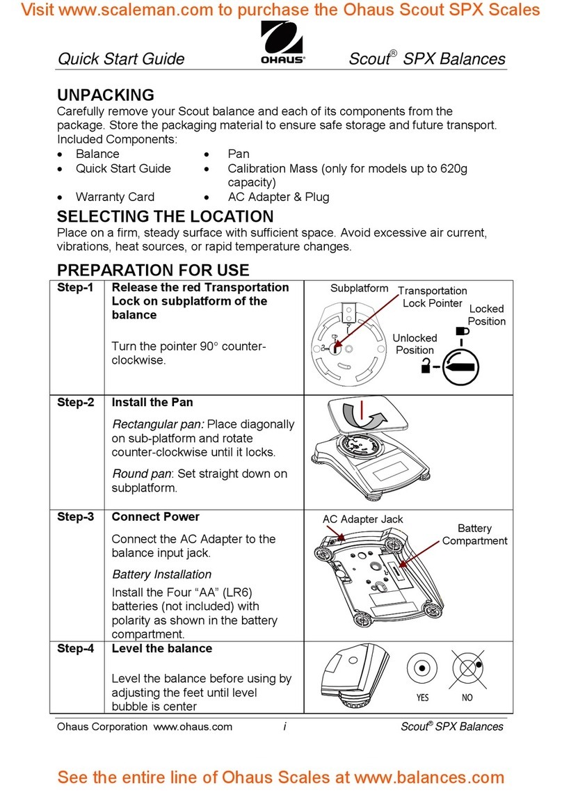
OHAUS Scout pro User manual

SERVICE MANUAL
SCOUT® PRO BALANCES
Ohaus Corporation 19A Chapin Road, P O Box 2033, Pine Brook, NJ 07058-2033 (973) 377-9000
SERVICE MANUAL
SCOUT® PRO BALANCES
The information ontained in this manual is believed to be a urate at the time of publi ation, but Ohaus
Corporation assumes no liability arising from the use or misuse of this material. Reprodu tion of this
material is stri tly prohibited.
Material in this manual is subje t to hange.
© Copyright 2003 Ohaus Corporation, all rights reserved.
® Registered trademark of Ohaus Corporation.
i
TABLE OF CONTENTS
CHAPTER 1 INTRODUCTION
1.1 Introdu tion .............................................................................................................1-1
1.2 Servi e Fa ilities .....................................................................................................1-1
1.3 Tools and Test Equipment Required.......................................................................1-2
1.3.1 Spe ial Tools and Test Equipment List ............................................................. 1-2
1.3.2 Standard Tools and Test Equipment List ...........................................................1-2
1.4 Test Masses Required ............................................................................................ 1-2
1.5 Spe ifi ations ..........................................................................................................1-3
CHAPTER 2 DIAGNOSIS
2.1 Troubleshooting ......................................................................................................2-1
2.2 Diagnosti Guide.....................................................................................................2-1
2.2.1 Diagnosis........................................................................................................... 2-1
2.3 Error Codes .............................................................................................................2-4
CHAPTER 3 REPAIR PROCEDURES
3.1 Repair Pro edures ..................................................................................................3-1
3.1.1 Cover Removal .................................................................................................. 3-1
3.1.2 Printed Cir uit Board Repla ement ...................................................................3-2
3.1.3 Transdu er Repla ement ..................................................................................3-4
CHAPTER 4 TESTING
4.1 Testing ....................................................................................................................4-1
4.1.1 Operation Test ...................................................................................................4-1
4.1.2 Segment Display Test........................................................................................ 4-1
4.2 Performan e Tests ..................................................................................................4-1
4.2.1 Repeatability Test ..............................................................................................4-2
4.2.2 Off-Center Load Test ..........................................................................................4-3
4.2.3 Linearity Test .....................................................................................................4-3
4.3 Down Stop Adjustment ............................................................................................4-4
CHAPTER 5 DRAWINGS AND PARTS LISTS
5.1 Drawings .................................................................................................................5-1
5.2 Parts Lists................................................................................................................ 5-3
APPENDIX A SERVICE TOOL INSTRUCTIONS
A. Servi e Tools Instru tions ...................................................................................... A-1
A.1 Requirements for S out Pro Tools ......................................................................... A-1
A.2 Software Installation ............................................................................................... A-1
A.3 Hardware Installation ............................................................................................. A-1
A.4 Spe ial Instru tions for USB Interfa e .................................................................... A-2
A.5 Using Configtool.Exe ............................................................................................. A-3
A.6 Final Servi e Calibration........................................................................................ A-5
Page No.
ii
LIST OF TABLES
TABLE NO. TITLE
1-1 Calibration Points ................................................................................................. 1-2
1-2 Spe ifi ations .......................................................................................................1-3
2-1 Diagnosti Guide .................................................................................................. 2-2
2-2 Error Codes ..........................................................................................................2-4
4-1 Types of Performan e Tests .................................................................................4-1
4-2 Test Masses .........................................................................................................4-3
4-3 Test Mass Values ................................................................................................. 4-5
4-4 Transdu er Adjustment Toleran es ......................................................................4-5
5-1 Repla ement Parts List ........................................................................................5-3
LIST OF ILLUSTRATIONS
FIGURE TITLE
3-1 Shipping Lo k.......................................................................................................3-1
3-2 Bottom of Balan e ................................................................................................ 3-1
3-3 Printed Cir uit Board removal...............................................................................3-2
3-4 Transdu er Removal ............................................................................................3-4
4-1 LCD Full Display ..................................................................................................4-1
4-2 Transdu er Front View - Down Stop Adjustment .................................................. 4-4
5-1 S out Pro Exploded View..................................................................................... 5-2
A-1 S rew and Housing Removal .............................................................................. A-2
A-2 Conne tor J3 Lo ation......................................................................................... A-2
A-3 Conne tor J3 Shorted .......................................................................................... A-2
A-4 S reen 1 .............................................................................................................. A-3
A-5 S reen 2 .............................................................................................................. A-4
A-6 S reen 3 .............................................................................................................. A-4
A-7 S reen 4 .............................................................................................................. A-5
B-1 IC U9 Conne tions .............................................................................................. B-2
Page No.
Page No.
APPENDIX B FACTORY CALIBRATIONS
B. Fa tory Calibrations ............................................................................................... B-1
B.1 Servi e Calibration................................................................................................. B-1
B.2 Fa tory Calibration ................................................................................................. B-3
Page No.
1-1
CHAPTER 1 INTRODUCTION
1 1 INTRODUCTION
This servi e manual ontains the information needed to perform routine maintenan e and servi e on
the Ohaus S out ® Pro Balan es. The ontents of this manual is ontained in five hapters and are
listed as follows:
Chapter 1 Introduction - Contains information regarding servi e fa ilities, tools, test equipment,
alibration masses and spe ifi ations.
Chapter 2 Diagnosis - Contains a diagnosti guide for troubleshooting problems and error ode
tables.
Chapter 3 Repair Procedures - Contains disassembly/assembly and repla ement pro edures.
Chapter 4 Testing - Contains an operational test, a segment display test and performan e tests.
Chapter 5 Drawings and Parts Lists - Contains an exploded view drawing and a parts list.
Before servi ing the balan e, you should be familiar with the Instru tion Manual whi h is pa ked with
every balan e. The pro edures in this manual assumes the te hni ian performing them has a working
knowledge of the use of standard hand tools and the repair of pre ision instruments.
1 2 SERVICE FACILITIES
To servi e the S out® Pro balan es, the servi e area should meet the following requirements:
 Should be temperature ontrolled and meet the balan e spe ifi ations for temperature
environmental requirements. See spe ifi ations for temperature ranges of the various
models.
 Must be free of vibrations su h as fork lift tru ks lose by, large motors, et .
 Must be free of air urrents or drafts from air onditioning/heating du ts, open windows,
people walking by, fans, et .
 Area must be lean and air must not ontain ex essive dust parti les.
 Work surfa e must be stable and level.
 Work surfa e must not be exposed to dire t sunlight or radiating heat sour es.
1-2
CHAPTER 1 INTRODUCTION
1 4 TEST MASSES REQUIRED
The masses required to test the S out Pro balan es must meet or ex eed the requirements of ASTM
Class 4 Toleran e. The alibration points are listed in Table 1-1.
TABLE 1-1. CALIBRATION POINTS
CAPACITY SPAN CAL POINT LINEARITY CAL POINTS
200g 200g 100g, 200g
400g 200g 200g, 400g
600g 300g 300g, 600g
2000g 2000g 1000g, 2000g
4000g 4000g 2000g, 4000g
6000g 6000g 3000g, 6000g
1 3 TOOLS AND TEST EQUIPMENT REQUIRED
In order to properly servi e the S out Pro balan es, ertain Ohaus spe ial tools and test items are
required in addition to standard ele troni tool kits. These items are listed as follows:
1 3 1 Special Tools and Test Equipment List
1. Alternate voltage Power Adapter if lo al power requirements do not mat h Balan e
Adapter voltage ratings.
2. S out Pro RS232 option PN 71147376.
3. A PC running Mi rosoft Windows NT 4.0 or later, or Mi rosoft Windows 98 or later.
3. S out Pro instru tion manual.
4. S out Pro Tools.zip.
5. Set of Feeler gauges ranging from 0.40mm/0.16in. to 0.65mm/0.026in.
6. Mi ro sized alligator lip.
1.3.2 Standard Tools and Test Equipment List
1. Standard Ele troni s Tool Kit.
2. Digital Voltmeter (DVM) Input impedan e of at least 10 megohms in the 1 Volt d position.
3. Masses totaling up to 6000 grams are required. Ohaus makes various alibration sets
available. Please onta t your nearest Ohaus dealer for further details.
1-3
CHAPTER 1 INTRODUCTION
1 5 SPECIFICATIONS
Spe ifi ations for the S out Pro balan es are listed in Table 1-2. When a balan e has been servi ed,
it must meet the spe ifi ations listed in the table. Before servi ing the balan e, determine what
spe ifi ations are not met.
TABLE 1-2. SPECIFICATIONS
Capa ity (g) 200 400 400 400 2000 4000 6000
Readability (g) 0.01 0.1
Repeatability (Std. Dev.) (g) 0.01 0.1
Off Center Loading (g) ±0.01 ±0.1
Linearity (g) ±0.01 ±0.1
Tare range To apa ity by subtra tion
Over Range Capa ity Capa ity + 90d
Stabilization Time 3 se onds
Operating Temp. Range 50° to 104° F/10° to 40° C
Power Requirements AC Adapter (in luded) 4 AA Batteries (not in luded)
Item Numbers SPx202 SPx402 SPx401 SPx601 SPx2001 SPx4001 SPx6000
1-4
CHAPTER 1 INTRODUCTION
2-1
CHAPTER 2 DIAGNOSIS
2 1 TROUBLESHOOTING
This se tion of the manual spe ifies problem areas of the balan e whi h an o ur. Information is
ontained to isolate spe ifi problems using Table 2-1, Diagnosti Guide, and Table 2-2, Error Codes.
Follow all dire tions step by step. Make ertain that the work area is lean and use are when handling
omponents of the balan e.
2 2 DIAGNOSTIC GUIDE
Table 2-1 is a diagnosti guide designed to help lo ate the problem area qui kly and easily. To use
the table, first lo ate the symptom that you are observing. Follow the symptom olumn and review the
probable ause olumn and remedy olumn. The probable auses are listed with the most ommon
ause first. If the first remedy does not fix the problem, pro eed on to the next remedy. Before
attempting to repair the Balan e, read all hapters of this manual to familiarize yourself with the
balan e omponents and operation. Do not attempt repairs unless you fully understand the operation
of the balan e.
2 2 1 Diagnosis
1. Isolate and identify the symptom.
2. Refer to Table 2-1 Diagnosti guide and lo ate the symptom.
3. Follow the suggested remedies in the order that they appear.
4. Perform the indi ated he ks, or see the appropriate se tion of the manual.
5. Repair or repla e the defe tive se tion of the balan e.
NOTE:
If more than one symptom is observed, it is ne essary to
approa h one area at a time, and also remember, that the
symptoms may be interrelated.
In the event that errati or flu tuating weight readings are observed, it is ne essary to isolate the
problem to either the me hani al area or the ele troni area of the balan e. The repeatability test will
qui kly point out whether the Transdu er (8) is operating properly or whether the problem is due to an
ele troni malfun tion.
If a problem arises that is not overed in this manual, onta t Ohaus Corporation for further information.
2-2
CHAPTER 2 DIAGNOSIS
REMEDY
1. Che k AC Adapter.
2. Repla e Power Ja k.
3. Repla e.
4. Clean or repla e.
5. Repla e PC Board.
1. Repla e battery.
2. Repla e AC Adapter.
3. Repla e PC Board.
1. Repla e battery.
2. Repla e PC Board.
1. Perform linearity alibra-
tion.
2. Set per spe ifi ations.
3. Plug in Transdu er.
4. Repla e Transdu er.
5. Repla e PC Board.
1. Use orre t masses.
2. Plug in Transdu er.
3. Repla eTransdu er.
4. Repla e PC Board.
1. Put pan on balan e
2. Che k stops and reset if
ne essary.
3. Perform fa tory alibra-
tion B.1 or B.2
TABLE 2-1. DIAGNOSTIC GUIDE
PROBABLE CAUSE
1. No power.
2. Power Ja k defe tive.
3. Weak battery.
4. Battery onne tor - poor
onta t.
5. PC Board defe tive.
1. Weak battery.
2. AC Adapter defe tive or
wrong type being used.
3. PC Board defe tive.
1. Weak battery.
2. PC Board defe tive.
1. Possible power surge.
2. Down stop improperly set.
3. Transdu er not on-
ne ted.
4. Defe tive Transdu er.
5. PC Board defe tive.
1. In orre t alibration
masses.
2. Transdu er not on-
ne ted.
3. Defe tive Transdu er.
4. PC Board defe tive.
1. Missing Pan.
2. Down Stop improperly
set.
3. Transdu er zero has shifted.
SYMPTOM
No display.
Low BAT displayed.
Stays in segment he k.
Always displays zero.
Cannot alibrate.
Displays (Err2)
2-3
CHAPTER 2 DIAGNOSIS
TABLE 2-1. DIAGNOSTIC GUIDE (Cont.)
SYMPTOM
Displays (Err2) (Cont.).
Ex eeds off enter load limit.
Ina urate readings.
Flu tuating readings.
Drifting display.
Error ode (Err#) on display.
PROBABLE CAUSE
4. Defe tive Transdu er.
5. PC board defe tive.
1. Defe tive Transdu er.
1. Improper alibration
(Span or Linearity).
2. Not zeroed before
weighing.
3. Defe tive Transdu er.
4. PC Board defe tive.
1. Unstable environment.
2. Debris in balan e.
3. PC Board defe tive.
4. Defe tive transdu er.
5. Transdu er Lo k en-
gaged or misaligned.
1. Balan e not warmed up.
2. Defe tive Transdu er.
3. PC Board defe tive.
1. Balan e has dete ted an
error ondition.
2. Defe tive Transdu er.
3. PC Board defe tive.
REMEDY
4. Repla e Transdu er.
5. Repla e PCB.
1. Repla e Transdu er.
1. Perform linearity alibra-
tion.
2. Press Zero On with no
weight on the Pan, then
weigh.
3. Repla e Transdu er.
4. Repla e PC Board.
1. Che k area for vibrations,
leveling and drafts.
2. Disassemble and lean if
ne essary.
3. Repla e PC Board.
4. Repla e Transdu er.
5. Unlo k or realign.
1. Allow balan e to stabi-
lize.
2. Repla e Transdu er.
3. Repla e PC Board.
1. See Table 2-2, Error
Codes.
2. Repla e Transdu er.
3. Repla e PC Board.
2-4
CHAPTER 2 DIAGNOSIS
2 3 ERROR CODES
S out Pro balan es are equipped with software whi h will display an error ondition when it o urs.
Table 2-2 Error Codes, des ribes the various error odes whi h an appear on the display and
spe ifies the probable reason and remedy.
TABLE 2-2. ERROR CODES
DISPLAY REASON ACTION
Err 1 Invalid he ksum data 1. Perform fa tory alibration.
2. Restore data file.
3. Che k transdu er.
4. Che k PCB.
Err 2 Overload or Underload 1. Make sure the right pan is on the balan e.
2. Perform servi e LIN alibration per B.1.
3. Che k transdu er.
4. Che k PCB.
Err 4 In orre t alibration mass 1. Calibrate using orre t mass.
Err 5 Parts ounting error 1. Sample is less than 1d. Change sample quantity
or in rease sample.
Err 8 RS232 buffer is full 1. Che k printing devi e.
Err 9 Internal data error 1. Restore data file.
2. Che k PCB.
3. Che k transdu er.
TABLE 2-1. DIAGNOSTIC GUIDE (Cont.)
SYMPTOM
RS232 Not fun tioning.
(On models equipped with
RS232).
PROBABLE CAUSE
1. Improper Print Menu set-
tings.
2. RS232 not turned on.
3. RS232 does not stay on.
4. Loose or dis onne ted
RS232 option.
5. RS232 option defe tive.
REMEDY
1 . C he k a l l s et t i n gs . ( Me n u
item Power must be set
to ON.)
2. Turn the option on. (See
instru tion manual).
3. If batteries are being
used, the RS232 turns
off w hen the unit is t urned
off. Either turn the option
on or use the a adapter.
4. Che k onne tion.
5. Repla e RS232 option.
3-1
CHAPTER 3 REPAIR PROCEDURES
3 1 REPAIR PROCEDURES
This se tion of the manual ontains detailed disassembly pro edures of the balan e. Refer to Figure
5-1. Before disassembling the balan e, it should be noted that omponents inside of the balan e are
deli ate and need to be handled with are. It is imperative that the Transdu er (8) should never be
subje ted to any ex essive torque, stress, or abrasion as damage may result. On e the balan e has
been disassembled, any small s rat h or abrasion made to any of the Individual Strain Gauges will
render the entire Transdu er (8) unusable. The Printed Cir uit Board (9) ontains integrated ir uits
whi h employ CMOS te hnology, therefore, aution must be exer ised so as not to subje t any of these
omponents to stati ele tri ity dis harge. When servi ing, a wrist Ground Strap with a 10 Megohm
series resistor to earth ground is highly re ommended. The Printed Cir uit Board (9) should be
handled by grasping the edges only and never pla ing fingers on any of the runs or tra es.
3 1 1 Cover Removal
To disassemble the balan e, pro eed as follows:
1. Turn the balan e off and if using an AC Adapter, dis onne t it from the balan e.
2. Remove the Pan (1, 2 or 3) from the balan e. Pan sizes and shapes vary.
3. Pla e the Shipping Lo k in the lo ked position.
See Figure 3-1. This will help prote t the
Transdu er.
12 Battery Compartment Cover
Cover S rew
Cover S rews
4 . I f a b at t e ry i s bei n g u s ed , tu r n t he b al a n e ov er a nd r emo ve t he B a t t e ry C omp ar t me nt C ov er
(12) as shown in Figure 3-2.
Figure 3-1. Shipping Lo k.
Figure 3-2. Bottom of Balan e.
Lo ked
Position
Pointer
Unlo ked
Position
3-2
CHAPTER 3 REPAIR PROCEDURES
3 1 1 Cover Removal (Cont )
5. Remove the 4 AA batteries from inside the battery ompartment and repla e the Battery
Compartment Cover (12).
6. Slide the Lo kswit h to to the unlo ked position to gain a ess to one of the over s rews.
Remove the 3 Cover S rews as shown in Figure 3-2.
7. Turn the balan e over in an upright position and arefully lift the Top Cover (6) from the
balan e Base (10).
8. After repairs and or adjustments have been made, reassemble the balan e in the reverse
order.
3 1 2 Printed Circuit Board (9) Replacement
In an effort to keep servi e osts down, it is suggested that if the Printed Cir uit Board (9) is suspe ted
of being faulty, it should be repla ed rather than repaired.
To repla e the Printed Cir uit Board (9) , pro eed as follows:
1. Remove the balan e over, refer to paragraph 3.1.1.
CAUTION
WHEN HANDLING THE PRINTED CIRCUIT BOARD,
HANDLE BY EDGES ONLY! DO NOT TOUCH FOIL SIDE
OF BOARD STATIC DISCHARGE MAY DAMAGE SOME
COMPONENTS
2. The Printed Cir uit Board (9) is fastened in pla e by 2 lips whi h are part of the Base (10)
and 2 s rews lo ated on top of the Printed Cir uit Board. In addition, a Calibration Lo k
(15)(small plasti pie e) is positioned at the front of the Printed Cir uit Board. See Figure
3-3.
Figure 3-3. Printed Cir uit Board Removal.
U9
CAL
J6 J11
LCD DISPLAY
U8
U7
J2
C4
BLK
RED
915
CLIP CLIP
MOUNTING
SCREW MOUNTING
SCREW
J6 CONNECTOR
10
PCB CAL LOCK
BASE
J11 RS232 CONNECTOR
J2 BATTERY
CONNECTOR
3-3
CHAPTER 3 REPAIR PROCEDURES
3 1 2 Printed Circuit Board (9) Replacement (Cont )
3. When an RS232 option is installed, remove the RS232 Conne tor from J11on the Printed
Cir uit Board (9).
4. Dis onne t the Transdu er able from Conne tor J6 on the Printed Cir uit Board (9).
5. Dis onne t the battery able from Conne tor J2 on the Printed Cir uit Board (9).
6. Remove the 2 mounting s rews on top of the Printed Cir uit Board (9).
7. Push the Printed Cir uit Board towards the ba k as far as it will go and apply a small forward
pressure to the Cal Lo k (15). Lift up on the front of the Printed Cir uit Board (9) to remove
it.
8. Install the new Printed Cir uit Board (9). Make sure that the Printed Cir uit Board is
positioned under the 2 lips on the Base (10).
9. Conne t the flexible able from the Transdu er to Conne tor J6 on the Printed Cir uit
Board (9).
10.Conne t the RS232 to Conne tor J11 on the Printed Cir uit Board (9) if the RS232 is
installed.
11. Conne t the battery able to onne tor J2 on the Printed Cir uit Board (9).
12.Repla e the 2 mounting s rews on top of the Printed Cir uit Board (9), make sure the board
is positioned as far forward as possible to ensure the alibration lo k swit h will operate
properly.
13. Reassemble the Balan e.
14.Repla e the batteries if previously removed.
15.See Appendix A Servi e Tools Instru tions and load temperature ompensation data.
16.Che k the performan e of the Balan e and perform Fa tory Calibration B.2.
3-4
CHAPTER 3 REPAIR PROCEDURES
3 1 3 Transducer (8) Replacement
There are 8 Transdu er Kits that are available for repla ement purposes. Ea h Kit is fully assembled
and onsists of metal base plate, a transdu er mounted to the base plate and a subplatform mounted
to the transdu er. All adjustments su h up stop and down stop (limits travel of the transdu er to safe
limits) have been fa tory set. Transdu er kits are available in the following ranges: 120g, 200g, 400g,
600g, 1200g, 2000g, 4000g and 6000g. Che k the bottom of the balan e and verify the apa ity before
ordering a new transdu er kit.
CAUTION
Extreme care must be exercised so as not to twist or
deform the Transducer in any way Do not drop or hit
the Transducer Any damage to the Transducer can
render it inoperative
1. Remove the over in a ordan e with the pro edures in paragraph 3.1.1.
2. Remove the 4 s rews that se ure the Transdu er (8) to the Base (10). The s rews are
a essible at the bottom of the balan e. See Figure 3-4.
3. Dis onne t Conne tor J6 oming from Transdu er (8).
4. Install the repla ement Transdu er using the 4 s rews previously removed and onne t the
Transdu er flexible able to onne tor J6 on the Printed Cir uit Board.
5. Reassemble the balan e.
6. See Appendix A Servi e Tools Instru tions and load temperature ompensation data.
7. Re alibrate the balan e in a ordan e with instru tions in Appendix B, Fa tory Calibration
B.2
8. Che k the performan e of the balan e.
Figure 3-4. Transdu er Removal.
U9
CAL
J6 J11
LCD DISPLAY
U8
U7
J2
C4
BLK
RED
TRANSDUCER
MOUNTING SCREWS
TRANSDUCER
MOUNTING
SCREWS
CONNECTOR J6
10 BASE
8 TRANSDUCER
4-1
CHAPTER 4 TESTING
4 1 TESTING
Before servi ing the balan e, an operational test and various performan e tests should be made to
as ertain whether or not the balan e meets spe ifi ations. Turn the balan e on and allow it warm up
for at least five minutes before performing these tests. Make sure the test area is free from drafts and
that the balan e rests on a level and vibration free surfa e. The masses used for final alibration must
be adjusted to ASTM Class 4 toleran e or better.
4 1 1 Operational Test
1. Conne t a fun tioning AC Adapter to the balan e Power Ja k lo ated at
the rear of the balan e.
2. Plug the AC Adapter into a suitable power sour e. If the AC Adapter supplied
with the balan e is rated for a different voltage, use an appropriate adapter to mat h the
supply voltage.
4 1 2 Segment Display Test
1. Turn the balan e on by pressing ON/ZERO Off, all segments are enabled and displayed
briefly, then followed by a software revision number. See Figure 4-1 for full display.
2. Tare the balan e. The display should indi ate a zero weight.
Figure 4-1. LCD Full Display.
4 2 PERFORMANCE TESTS
A urate performan e of a S out Pro balan e is determined by a series of three performan e tests. The
displayed readings are ompared with the toleran es listed in Table 4-1. Toleran e values are
expressed in ounts. A one ount hange is equal to the last digit shown on the balan e display.
TABLE 4-1. TYPES OF PERFORMANCE TESTS
PERFORMANCE TEST TOLERANCE
Repeatability +1 Count
Off Center Load +2 Count
Linearity +1 Count
4-2
CHAPTER 4 TESTING
4 2 PERFORMANCE TESTS (CONT )
The following performan e tests are used to evaluate the balan e operation before and after repairs.
Ea h balan e tested must meet the requirements spe ified in ea h test as well as the spe ifi ations
listed in Table 1-2. Toleran e values are expressed in ounts. A balan e whi h passes ea h of these
three tests meets the manufa turing spe ifi ations.
4 2 1 Repeatability Test
Repeatability is a word used in balan e spe ifi ations meaning the Standard Deviation of a set of
similar weight readings. To determine whether a balan e meets the al ulated Standard Deviation
value in the Spe ifi ation Table 1-2, perform the following test:
Test
1. Tare the balan e. The reading on the display should be 0g.
2. Sele t a mass weighing near the maximum apa ity of the balan e and pla e the mass on
the center of the Pan (1). Observe and re ord the reading.
3. Remove the mass. Reading should return to 0g +1 ount.
4. Repeat this test for ten readings. If the standard deviation of the readings is less than +1
ount, the balan e passes the Repeatability Test.
Adjustment
If the deviation for any set of readings (using the same mass pla ed on the enter of the Pan) is greater
than +1 ount, the balan e does not meet the Repeatability Test spe ifi ation. Inspe t and orre t the
following areas:
1. Che k for me hani al obstru tions. Any foreign obje t tou hing any part of the moving Pan
an ause a balan e to fail the Repeatability Test. Inspe t and orre t as ne essary.
2. An error in the Off-Center Load Test an affe t the results of the Repeatability Test. Inspe t
and orre t if ne essary. See Off-Center Load Test.
3. Foreign material or debris lo ated in the balan e between the Pan (1) and the Top Cover
(6) an ause the balan e to fail the test.
4. Environmental influen es su h as vibrations, drafts or a non-level surfa e an also ause
failures.
5. If the balan e fails the test, refer to table 2-1 Diagnosti Guide for assistan e.

Other manuals for Scout pro

5

This manual suits for next models

11

Other OHAUS Scale manuals

OHAUS JE 120 User manual

OHAUS

OHAUS JE 120 User manual

OHAUS Guardian 2000 User manual

OHAUS

OHAUS Guardian 2000 User manual

OHAUS Scout STX User manual

OHAUS

OHAUS Scout STX User manual

OHAUS Ranger 3000 Series User manual

OHAUS

OHAUS Ranger 3000 Series User manual

OHAUS TP200S User manual

OHAUS

OHAUS TP200S User manual

OHAUS A32P3T series User manual

OHAUS

OHAUS A32P3T series User manual

OHAUS Defender 3000 User manual

OHAUS

OHAUS Defender 3000 User manual

OHAUS GT4100DG User manual

OHAUS

OHAUS GT4100DG User manual

OHAUS 1400 Series Manual

OHAUS

OHAUS 1400 Series Manual

OHAUS CL Series User manual

OHAUS

OHAUS CL Series User manual

OHAUS 700 Series Quick start guide

OHAUS

OHAUS 700 Series Quick start guide

OHAUS PJX Series User manual

OHAUS

OHAUS PJX Series User manual

OHAUS Scout STX Operating manual

OHAUS

OHAUS Scout STX Operating manual

OHAUS Scout pro User manual

OHAUS

OHAUS Scout pro User manual

OHAUS Dial-O-Gram User manual

OHAUS

OHAUS Dial-O-Gram User manual

OHAUS EC Series User manual

OHAUS

OHAUS EC Series User manual

OHAUS RC31P1502-M User manual

OHAUS

OHAUS RC31P1502-M User manual

OHAUS 1119D User manual

OHAUS

OHAUS 1119D User manual

OHAUS CS200P User manual

OHAUS

OHAUS CS200P User manual

OHAUS GT 210 Manual

OHAUS

OHAUS GT 210 Manual

OHAUS Carat User manual

OHAUS

OHAUS Carat User manual

OHAUS Adventurer AX124 User manual

OHAUS

OHAUS Adventurer AX124 User manual

OHAUS CL Series User manual

OHAUS

OHAUS CL Series User manual

OHAUS Scout SKX Series User manual

OHAUS

OHAUS Scout SKX Series User manual

Popular Scale manuals by other brands

Jata hogar 499 Instructions of use

Jata hogar

Jata hogar 499 Instructions of use

ETEKCITY EBS-C121-KUS user manual

ETEKCITY

ETEKCITY EBS-C121-KUS user manual

Adler Europe AD 8165 user manual

Adler Europe

Adler Europe AD 8165 user manual

Aurora AU 4304 manual

Aurora

Aurora AU 4304 manual

SAPIRHOME ES-1650-B instruction manual

SAPIRHOME

SAPIRHOME ES-1650-B instruction manual

KERN PBJ-N Service manual

KERN

KERN PBJ-N Service manual

Gibertini EU-C Gold Series instruction manual

Gibertini

Gibertini EU-C Gold Series instruction manual

Acom NETS operating manual

Acom

Acom NETS operating manual

Gram S4 Series user manual

Gram

Gram S4 Series user manual

Sartorius Entris II BCA Advanced Series operating instructions

Sartorius

Sartorius Entris II BCA Advanced Series operating instructions

Accuris W3100 Series operating manual

Accuris

Accuris W3100 Series operating manual

acaia Coffee Scale Operation manual

acaia

acaia Coffee Scale Operation manual

Tree HRB 30001 Operation manual

Tree

Tree HRB 30001 Operation manual

AENO KS1S quick start guide

AENO

AENO KS1S quick start guide

Eagle EHP 02 Series user manual

Eagle

Eagle EHP 02 Series user manual

Lacor 61700 Instructions for use and maintenance

Lacor

Lacor 61700 Instructions for use and maintenance

Saturn ST-PS0237 manual

Saturn

Saturn ST-PS0237 manual

AND HL-200 instruction manual

AND

AND HL-200 instruction manual

manuals.online logo
manuals.online logoBrands
  • About & Mission
  • Contact us
  • Privacy Policy
  • Terms and Conditions

Copyright 2025 Manuals.Online. All Rights Reserved.