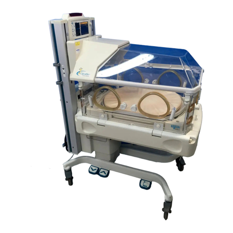
Ohmeda Ohio 2000 IWS Series User manual

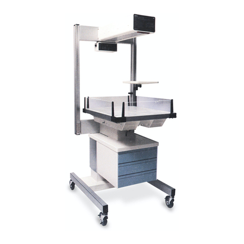
Ohio®Infant Warmer
Systems
All Models
Operation and Maintenance Manual

i6600-0255-000 12/20/00
Table of Contents
i
This Product will perform in conformity with the description thereof contained
in this operating manual and accompanying labels and/or inserts, when
assembled, operated, maintained and repaired in accordance with the instruc-
tions provided. This Product must be checked periodically. A defective Product
should not be used. Parts that are broken, missing, plainly worn, distorted or
contaminated should be replaced immediately. Should such repair or replace-
ment become necessary, Ohmeda Medical recommends that a telephone or
written request for service advice be made to the nearest Ohmeda Medical
Regional Service Center. This Product or any of its parts should not be
repaired other than in accordance with written instructions provided by
Ohmeda Medical and by Ohmeda Medical trained personnel. The Product
must not be altered without the prior written approval of Ohmeda Medical’s
Quality Assurance Department. The user of this Product shall have the sole
responsibility for any malfunction which results from improper use, faulty
maintenance, improper repair, damage, or alteration by anyone other than
Ohmeda Medical.
CAUTION: U.S. Federal law restricts this device to sale by or on the order
of a licensed medical practitioner.
User Responsibility
w

i6600-0255-000 12/20/00
Table of Contents
i
Table of Contents
Model Descriptions ........................................................................................................v
Definitions.....................................................................................................................vii
General Precautions .....................................................................................................ix
Warnings........................................................................................................ ix
Cautions....................................................................................................... xiii
1/Description
1.1 General .............................................................................................. 1-1
1.2 Support Structure ............................................................................... 1-1
1.3 Heater Assembly................................................................................ 1-1
1.4 Control Unit ........................................................................................ 1-2
1.5 Bed Platform ...................................................................................... 1-2
1.6 Bassinet ............................................................................................. 1-2
1.7 Accessories........................................................................................ 1-3
2/Setup and Checkout Procedure
2.1 Setup.................................................................................................. 2-1
2.2 Mechanical Checkout Procedure ....................................................... 2-1
A. Overall Appearance................................................................... 2-1
B. Heater Assembly Rotation......................................................... 2-2
C. Mechanical Checks ................................................................... 2-2
D. Warmer/Bassinet Interlock (model 3500 only) .......................... 2-3
E. Warmer/Bassinet Unlock ........................................................... 2-3
F. Accessory Checks ..................................................................... 2-3
G. Wall Mount Checkout ................................................................ 2-4
2.3 Control Unit Checkout Procedure ...................................................... 2-4
A. Control Unit Check .................................................................... 2-5
B. Elapsed Timer Check ................................................................ 2-6
C. Observation Light Check ........................................................... 2-6
D. Raise and Lower Bed Switch Check (Elevating Models Only) .. 2-6
E. Interlock Switch Check .............................................................. 2-7
F. Power Failure, Memory and Battery Test (all models except the
2001 International) .................................................................... 2-7
3/Operation
3.1 Control Panel Operation..................................................................... 3-1
A. Displays ..................................................................................... 3-1
B. Indicator Lights .......................................................................... 3-2
C. Switches .................................................................................... 3-2
D. Alarms ....................................................................................... 3-4
3.2 Manual and Servo Mode Operation ................................................... 3-7
3.3 Elapsed Timer Operation ................................................................. 3-11

ii 6600-0255-000 12/20/00
Table of Contents
ii
3.4 Bassinet Operation (model 3500 only)............................................. 3-11
3.5 Bed Platform Operation.................................................................... 3-12
3.6 Side Panel Operation ....................................................................... 3-13
3.7 X-ray Procedures ............................................................................. 3-14
3.8 Oxygen Administration ..................................................................... 3-16
3.9 Gas Cylinder Installation and Operation .......................................... 3-16
3.10 Mounting Accessories ...................................................................... 3-18
A. Mounting and Releasing Procedure ........................................ 3-19
B. Adapter Plate Mounting and Releasing Procedure ................. 3-19
C. ECMO Adapter ........................................................................ 3-20
3.11 ThermaLink Options......................................................................... 3-20
Using the Serial Data Interface ........................................................ 3-21
Using the Nurse Call System Interface ............................................ 3-21
Nurse Call checkout ......................................................................... 3-22
3.12 Rotating Drawer Option.................................................................... 3-22
4/Cleaning and Disinfecting
4.1 Cleaning ............................................................................................. 4-1
4.2 Wood Surfaces (model 3500 only)..................................................... 4-2
4.3 Reusable Skin Temperature Probe.................................................... 4-2
5/Maintenance
5.1 Repair Policy and Procedure ............................................................. 5-1
5.2 Circuit Breaker Reset ......................................................................... 5-2
5.3 Lamp Replacement ............................................................................ 5-2
A. Alarm Lamp Replacement ......................................................... 5-2
B. Observation Lamp Replacement............................................... 5-3
5.4 Yoke Manifold Assembly.................................................................... 5-5
5.5 Battery Test........................................................................................ 5-5
5.6 Maintenance Schedule....................................................................... 5-6
A. Operator Maintenance............................................................... 5-6
B. Service Maintenance ................................................................. 5-6
6/Illustrated Parts
Appendix
Temperature Conversion Chart .................................................................. A-1
Servo Mode Algorithm ................................................................................ A-2
Infant Warmer System Specifications......................................................... A-2
Electrical............................................................................................. A-2
Controller............................................................................................ A-3
Alarms ................................................................................................ A-4
Environmental Specifications ............................................................. A-5
Electromagnetic Compatibility (EMC) ................................................ A-6

iii 6600-0255-000 12/20/00
Table of Contents
iii
Mechanical (Without Accessories) ..................................................... A-6
3500 Bassinet .................................................................................... A-7
Accessories........................................................................................ A-8
Radiant Energy Distribution ............................................................. A-10
Thermalink Option Specifications ............................................................. A-10
Hewlett Packard CMS Monitor (Vuelink).......................................... A-10
SpaceLabs Monitor (Flexport)........................................................... A10
Serial data ........................................................................................ A-10
Nurse Call specifications.................................................................. A-12
Installing wall mounted units..................................................................... A-13
Pre-Installation Preparation.............................................................. A-13
Warmer Installation .......................................................................... A-14
Warranty

iv 6600-0255-000 12/20/00
Table of Contents
iv
Notes

v6600-0255-000 12/20/00
Table of Contents
v
Model Descriptions
CI.13.004, CI.13.005, CI.13.006 CI.11.003, CI.05.071, CI.05.072, CI.05.073CI.05.074, CI.11.003, CI.05.075, CI.10.022
4000 IWS 4300 IWS 4400 IWS
3150 IWS 3300 IWS 3400 IWS 3500 IWS
2001 IWS (international only) 3000 IWS 3050 IWS 3100 IWS

vi 6600-0255-000 12/20/00
Table of Contents
vi
All models of the Ohmeda Medical Infant Warmer System provide a controlled
source of radiant heat for infants and pediatric patients. The control system uses
a microprocessor and provides both manual and servo modes of operation
(except for the 2001 International, which is manual mode only).
The model 2001 International has an integral infant bed and is a manual mode
only warmer designed for short term attended care in the OR and L&D.
The wall mounted 3050, 3100 and 3150 models are available to accommodate
specific architectural requirements in the NICU, L&D, LDR and LDRP room .
The 3050 is a heater head only, the 3100 is a heater and dove tail rails, and the
3150 includes a heater, rails and integral bed.
The model 3300 has an integral bed for infants and is intended for procedures
and long term care in the Nursery and L&D The model 3400 is the same as the
3300, except it has an elevating pedestal to raise and lower the bed .
The model 3000, 3500 and 4000 are free standing Warmers which can be used
over a variety of infant bassinets in the general nursery, over post-operative
patients, during patient feeding, and in any other application where controlled
radiant heat is required.
The 3500 System also has a detachable Bassinet for infants, and is intended for
procedures and long term care in the Nursery, L&D, LDR and LDRP Rooms.
The model 4300 and 4400 have a larger size bed than the model 3300 and are
intended for surgical procedures and long term care in the Nursery and L&D
Rooms. The model 4400 has an elevating pedestal to raise and lower the bed-
to-floor height. The model 4300 is a non-elevating version of the 4400.
IWS Model Options
Standard Heater/Bed Large Heater/Bed
2000 3000 3500 4000
Series Series Series Series
Free Standing 3000 3500† 4000
Wall mounted,
heater head only 3050
Wall mounted heater
with rails 3100
Wall mounted heater
with rails and bed 3150
Free standing with
integral bed 2001 3300 4300
Elevating pedestal 3400 4400
† Detachable bassinet and wood grain finish standard.
Model Descriptions

vii 6600-0255-000 12/20/00
Table of Contents
vii
Note: A Note provides additional information to clarify a point in the text.
Important: An Important statement is similar to a note but used for greater
emphasis.
CAUTION: A Caution statement is used when the possibility of damage to the
equipment exists.
WARNING: A Warning statement is used when the possibility of injury to the
patient or the operator exists.
Symbols
Attention! Consult the manual for more information.
Type B equipment.
Functional Earth Terminal
Protection Earth Terminal
Increase % Power or Control Temperature
Decrease % Power or Control Temperature
Alarm Silence
Alternating Current
Do not place an infant on this surface
Definitions
w
w
w
x
m
M
?
y
∏
ı

viii 6600-0255-000 12/20/00
Table of Contents
viii
Notes

ix 6600-0255-000 12/20/00
Table of Contents
ix
ww
ww
wWarnings
Before using the Ohmeda Medical Infant Warmer System, read this entire
manual. Attempting to use this device without a thorough understanding of its
operation may result in patient or user injury. This device should only be
operated by personnel trained in its operation and under the direction of
qualified medical personnel familiar with the risks and benefits of this type of
device. Additional precautions specific to certain procedures are found
in the text of this manual.
Do not use the Warmer in the presence of flammable anesthetics; a possible
explosion hazard exists under these conditions.
Do not perform the Checkout Procedures (Mechanical and Control Unit) while
a patient occupies the Warmer.
Complete the “Checkout Procedures” section of this manual before putting the
unit into operation. If the warmer fails any portion of the checkout procedures it
must be removed from use and repaired.
Do not use the Warmer system if the system failure alarm is activated. Remove
the unit from service and refer to qualified personnel for repair.
ww
ww
wCautions
Only competent individuals trained in the repair of this equipment should
attempt to service it as detailed in the service manual. The Service Manual
provides detailed information solely for use by individuals having proper
knowledge, tools and test equipment, and for service representatives trained
by Ohmeda Medical.
General Precautions

x6600-0255-000 12/20/00
Table of Contents
x
Notes

1-1 6600-0255-000 12/20/00
1/Description
1-1
1/Description
In this section
1.1 General ...............................................................................................................1-1
1.2 Support Structure ................................................................................................1-1
1.3 Heater Assembly.................................................................................................1-1
1.4 Control Unit .........................................................................................................1-2
1.5 Bed Platform .......................................................................................................1-2
1.6 Bassinet (3500 Series)........................................................................................1-2
1.7 Accessories.........................................................................................................1-3
1.1 General
All models of the Ohmeda Medical Infant Warmer System provide a controlled source of
radiant heat for infants and pediatric patients. The control system uses a microprocessor
and provides both manual and servo modes of operation (model 2001 International is
manual mode only). The patient temperature, control temperature, and elapsed time
displays are digital for ease of viewing. The control panel includes a one hour elapsed
timer with time displayed in minutes and seconds. The timer features optional audible
tones for use during Apgar scoring. A complete audio and visual alarm system is in-
cluded on the control panel.
The optional ThermaLink feature simplifies charting and monitoring. RS-232 serial data
is provided for use with customized research software or compatible vital signs monitors.
The Nurse Call connection lets you integrate the Warmer into your current or future
remote alarm systems.
1.2 Support Structure
The support structure provides excellent stability for the radiant heater and optional accessories.
On free standing units, the support structure consists of the base assembly and the uprights with
an integral rail system. The rails provide a means for mounting accessories and ancillary equip-
ment to the unit. Refer to Section 1.7 for a description of the accessory items.
1.3 Heater Assembly
The warmer is designed to warm infants on a bed surface located beneath the heater assembly.
WARNING: wBed-to-heater spacing less than the recommended 64 cm will result in incor-
rect operation and may adversly affect the patient’s condition.
For your convenience, on Model 3000, 3100, 3500, and 4000 the proper bed-to-heater
spacing is indicated by a label located on the right aluminum upright (as viewed from the
front).
Warmers shipped since 1993 have high wattage heaters that allow bed to heater spac-
ing of 69 + 5 - 23 cm, making them compatible with many kinds of bassinets.
Since very low birth weight babies may require tighter control of the heat provided to
them, we recommend that on warmer models that incorporate a built-in bed and are
intended for care of low birth weight babies, the distance between heater and bed be
maintained at 69±5 cm.

1-2 6600-0255-000 12/20/00
1/Description
1-2
The heater assembly consists of a radiant heater, parabolic reflector, observation light,
and a visual alarm light. The parabolic reflector focuses radiant energy on the bed
surface, minimizing energy loss due to scattering and providing an even field of radiant
heat over the bed surface. The observation light provides intense light for procedures.
The alarm light is located on the end of the heater assembly for ease of viewing. The
entire heater assembly rotates to the side for X-ray procedures and for observation
lamp replacement.
1.4 Control Unit
The control unit contains the electronic circuits and controls used to operate the radiant
heater and the observation light. The control unit performs regular self checks during
its operation including failure diagnostics.
Either manual or servo mode of operation may be selected. In the manual mode of
operation, select the level of radiant heat output as indicated by the % power display
on the control panel. The control circuit then maintains the selected level of radiant
heat. The manual mode has a preheat setting which allows the Warmer to be pre-
heated. In the servo mode of operation, select the patient’s control temperature. A skin
temperature probe is used to monitor the patient skin temperature. The control system
modulates the radiant heat to maintain the patient at the selected control temperature.
The patient’s skin temperature is continuously displayed.
Alarms activate to alert the operator of a low or high patient temperature, a skin tem-
perature probe failure, a power failure, equipment failure or a check patient prompt.
1.5 Bed Platform
Warmers with beds include a mattress and transparent side panels. The side panels
fold down for easy access to the patient and can be removed for cleaning. The X-ray
cassette tray (located in an opening beneath the bed when installed) pulls out for
insertion of X-ray cassettes and allows X-rays to be taken without moving the patient.*
Markings located along the side panels allow easy location of the cassette in the X-ray
tray relative to the position of the patient on the warmer bed.* The tiltable bed platform
allows Trendelenburg and reverse Trendelenburg positioning. The hydraulic system for
the tiltable bed provides a smooth, dampened motion to avoid disturbing the patient.*
A chest drainage hanger attached to the bed and rear cross bar extrusion provides a
convenient location to hang chest drainage devices.*
1.6 Bassinet (3500 Series)
The bassinet unit can be detached and rolled away from the model 3500 warmer unit
by pulling up on the locking lever knob located at the top rear of the bassinet (see
Figure 1-1). The bassinet includes:
1. Transparent locking side panels which fold down for easy patient access and are
removable for cleaning.
* Not available on the model 3500 warmer.

1-3 6600-0255-000 12/20/00
1/Description
1-3
2. A mattress.
3. A tiltable, positive-lock bed platform which allows Trendelenburg and reverse
Trendelenburg positioning at 4° and 8° tilt positions .
4. Three drawers which open from the front (or from the side in an optional configura-
tion) for storing equipment or supplies. The top drawer is provided with a key lock.
5. Front locking casters.
CI.10.017
UNLOCK
UNLOCK
UNLOCK
UNLOCK
Figure 1-1
Operating the bassinet locking lever knob
1.7 Accessories
The rail mounting system is the basis for most of the accessories for the Warmer. This
patented design consists of a dovetail shaped aluminum extrusion and a positive
locking mounting block. Mounting blocks are attached to various accessories for
mounting to the rail system. The mounting blocks are produced in two standard lengths
and are machined to accommodate each specific accessory.
Accessories which mount on a single upright are interchangeable between all model
Warmers.
Accessories can only be mounted to the inside dovetail rail on each upright of the 3500
Warmer.

1-4 6600-0255-000 12/20/00
1/Description
1-4
Notes

2-1 6600-0255-000 12/20/00
2/Setup and Checkout Procedures
2-1
2/Setup and Checkout Procedures
In this section
2.1 Setup...................................................................................................................2-1
2.2 Mechanical Checkout Procedure ........................................................................2-1
A. Overall Appearance .......................................................................................2-1
B. Heater Assembly Rotation .............................................................................2-2
C. Mechanical Checks........................................................................................2-2
D. Warmer/Bassinet Interlock (model 3500 only)...............................................2-3
E. Warmer/Bassinet Unlock (model 3500 only) .................................................2-3
F. Accessory Checks .........................................................................................2-3
G. Wall Mount Checkout.....................................................................................2-4
2.3 Control Unit Checkout Procedure .......................................................................2-4
A. Control Unit Check.........................................................................................2-5
B. Elapsed Timer Check ....................................................................................2-6
C. Observation Light Check ...............................................................................2-6
D. Raise and Lower Bed Switch Check (Elevating Models Only) ......................2-6
E. Interlock Switch Check ..................................................................................2-7
F. Power Failure, Memory and Battery Test (all models except the
2001 International).........................................................................................2-7
2.1 Setup
Refer to the setup instructions shipped with the warmer for initial unpacking and setup of
the unit after shipment. For model 3050, 3100 and 3150 wall mounted units, refer to the
mounting instructions in the Appendix.
After removal from the shipping containers, inspect the Ohmeda Infant Warmer System and
all accessory items for any signs of damage which may have occurred during shipment. File
a damage claim with the shipping carrier if damage has occurred. Also confirm the pres-
ence of all accessory items or factory installed options as listed on the packing slip.
2.2 Mechanical Checkout Procedure
WARNING: wBefore using the Ohmeda Infant Warmer System, read this entire manual.
Attempting to use this device without a thorough understanding of its
operation may result in patient or user injury.
wDo not perform the Checkout Procedures (Mechanical and Control Unit)
while a patient occupies the warmer.
wComplete the “Checkout Procedures” section of this manual before putting
the unit into operation. If the warmer fails any portion of the checkout
procedures it must be removed from use and repaired.
A. Overall Appearance
1. Disconnect the power cord from the ac power source for the mechanical checks
portion of this procedure.
2. Check the overall appearance of the Infant Warmer/ Bassinet System. There should
be no obvious damage.

2-2 6600-0255-000 12/20/00
2/Setup and Checkout Procedures
2-2
3. For the model 3500, separate the warmer from the bassinet.
4. For units with casters, check that all casters are in firm contact with the floor and that
the warmer is stable and moves freely.
For the model 3500, check that all six casters on the warmer move freely.
Note: On the model 3500, it is possible that the two center casters may not be in
contact with the floor at all times.
5. Lock the two front casters and check that the warmer is held in place. On the model
3500, lock the two rear casters and check that the warmer is held in place.
6. For the model 3500, place the bassinet on a level surface. Check that all four
casters are in firm contact with the floor and that the Bassinet moves freely.
7. For the model 3500, lock the two front casters and check that the Bassinet is held in place.
8. Examine the power cord for damage. Replace the power cord if damage is evident.
9. Examine the unit for objects placed on top of the heater assembly.
10. Check heater-to-bed spacing falls within ranges specified in "1.3 Heater Assembly".
WARNING: wDo not place any accessories or other objects directly over the bed sur-
face. This may block radiant heat energy and lead to cooling of the infant.
wDo not place items on top of the heater assembly. Items placed on top of
the heater assembly can fall and injure the patient, prevent adequate
ventilation of the heater assembly, and may pose a fire hazard.
B. Heater Assembly Rotation
Rotate the Heater Assembly to the side and then back to the normal position. Check for
a smooth rotation.
C. Mechanical Checks
1. Check the operation of the bed sides. The bed sides should operate smoothly.
WARNING: wRegularly inspect the bed side panel latching mechanism, and the bedside
locking mechanism on the model 3500, to ensure proper operation and to
prevent the infant falling off the bed.
2. Check the operation of the tilt mechanism. Verify that the bed platform operates
smoothly and locks in normal, Trendelenburg and reverse Trendelenburg positions.
3. If the drawer package is installed, check that all the drawers open and close freely.
On units with the rotating drawer package, make sure the drawers rotate from front
to 90° left and right and firmly stop in the detented positions.
WARNING: wOverloading the drawers can affect the stability of the unit. Limit the load
to 4.6 kg per drawer.
4. For the model 3500 bassinet, remove the keys from the top drawer and lock it.
Check that the drawer is securely held closed.

2-3 6600-0255-000 12/20/00
2/Setup and Checkout Procedures
2-3
D. Warmer/Bassinet Interlock (model 3500 only)
1. Lock the 3500 warmer’s two rear casters.
2. Align the rear of the bassinet with the warmer’s base.
3. Push the bassinet into the alignment/locking track of the warmer’s base.
4. Continue pushing the bassinet until its locking pin drops into the socket at the end
of the alignment track. There should be an audible click when the pin drops into
position.
5. Lightly push and pull the bassinet to verify that the two units are securely held
together.
6. Unlock the two rear casters on the warmer and check that the combined unit
moves smoothly.
E. Warmer/Bassinet Unlock (model 3500 only)
1. Verify that the two bassinet front casters are unlocked and the two warmer rear
casters are locked .
2. With the locking pin handle (located at the rear of the bassinet) raised, pull the
bassinet forward until it is fully detached from the warmer .
CAUTION: wTo prevent the drawers from opening unintentionally while moving the de-
tached bassinet, move it from the front only.
F. Accessory Checks
Perform these checks if they are applicable.
1. Check that all accessories are mounted securely and that the load limits are not
exceeded.
2. Check that all gas accessories are installed and operating properly (refer to Section 3.9).
3. Where applicable, perform the checkout procedures detailed in the Operation and
Maintenance Manuals for the accessories.
WARNING: wLimit the load of accessories to 23 kg per side on the Warmer to ensure
stability. Always try to evenly distribute the weight of accessories on both
sides of the unit for a more balanced load. Accessories should not be
mounted more than 142 cm above the floor. For models 3000 and 3500,
limit the load of accessories to 9 kg maximum per side mounted no more
than 112 cm above the floor.
wDue to the increased height of units with the ECMO option installed, a
tipping hazard may exist. Limit the total accessory load to 23 kg, no more
than 11 kg per side.

2-4 6600-0255-000 12/20/00
2/Setup and Checkout Procedures
2-4
G. Wall Mount Checkout
CI.14.096
Figure 2-1
Wall mount pin insertion
1. Verify that the warmer is rigidly secured to the wall and the heater assembly is level.
Note: To access the control unit and display module for service procedures, either
hinge pin may be removed, allowing the warmer to pivot away from the wall.
2. Check that both hinge pins are in place and fully inserted with the pin heads at the
top of the hinge.
WARNING: wIn the service position the strength of the hinge bracket is reduced. Never place a
patient in the bed when the heater is in the service position. Never leave the unit
unattended in the service position or with either pin removed.
CI.14.104
Patient
Temperature Elapsed
Time Display
Control
Temperature Heater
Power %
Increase
Decrease Elapsed Time
Start/Hold
and Reset
100
75
50
25
5
°C
°C
Start
Hold
Patient Temperature
Alarms
Probe Failure
Patient Temp
System Failure
Heat Off
Check Patient
Power Failure
Reset
Tones
On / Off
Apgar
Preheat
Light
On / Off
Mode
Control Temperature % Power Elapsed Time
Bed Height Servo
Manual
Bed
Controls*
Light
On/Off
Switch
Apgar
Tones
On/Off
Apgar
Indicator
Alarm
Lights* Alarm
Silence Mode
Switch*
Mode
Indicators*
* Note: Servo mode indicator, mode switch, and probe failure alarm are not present on the model 2001 international control
panel. Bed raise/lower are only present on elevating models.
Figure 2-2
Control Panel
2.3 Control Unit Checkout Procedure
WARNING: wDo not perform the Checkout Procedures (Mechanical and Control Unit)
while a patient occupies the warmer.
wComplete the “Checkout Procedures” section of this manual before
putting the unit into operation. If the warmer fails any portion of the
checkout procedures it must be removed from use and repaired.
This manual suits for next models
14
Table of contents
Other Ohmeda Medical Equipment manuals
Popular Medical Equipment manuals by other brands

Ametek
Ametek Reichert Endurance Tilt Chair and Stand user guide

Respironics
Respironics C-Flex M Series user manual

Medirol
Medirol VIVERA FASTENER F401 Operation and maintenance manual

Practicon
Practicon Acu-Tip quick start guide

bort medical
bort medical 103 700 quick guide

Teeter
Teeter Neck Relax & Restore Duo Assembly & user instructions