4.
Attach
the
lamp-head
and
articulating
arm
assembly
to
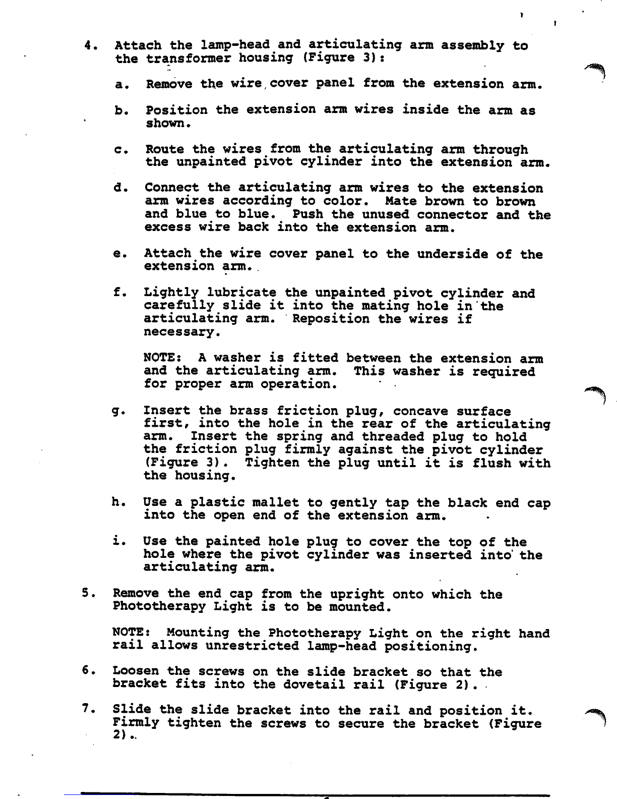
the transformer housing (Figure
3):
a.
Remove
the
wire
cover
panel
from
the
extension
arm.
b.
Position
the
extension
arm
wires
inside
the
arm
as
shown•
c.
Route
the
wires
from
the articulating arm through
the unpainted pivot cylinder into the extension
arm.
d. Connect the articulating arm wires to the extension
arm wires according to color. Mate brown to brown
and
blue
to
blue.
Push
the
unused
connector
and
the
excess
wire
back
into
the
extension
arm.
e.
Attach the wire
cover
panel
to the underside of the
extension
arm.
f.
Lightly lubricate the unpainted pivot cylinder and
carefully slide it into the mating hole in the
articulating
arm.
Reposition the wires if
necessary.
NOTE: A
washer
is
fitted
between
the
extension
arm
and
the
articulating
arm.
This
washer
is
required
for proper arm operation.
g.
Insert the brass friction plug, concave surface
first,
into
the
hole
in the
rear
of the articulating
arm. Insert the spring and threaded plug to hold
the
friction
plug
firmly
against the pivot cylinder
(Figure
3)
. Tighten the plug until it is flush with
the housing.
h.
Use a
plastic
mallet
to
gently
tap the
black
end cap
into the open end of the extension arm.
i.
Use the
painted
hole
plug
to
cover
the top of the
hole where the pivot cylinder was inserted
into"
the
articulating
arm.
5.
Remove the end cap from the upright onto which the
Phototherapy Light is to be mounted.
NOTE: Mounting the Phototherapy Light on the right hand
rail
allows
unrestricted
lamp-head
positioning.
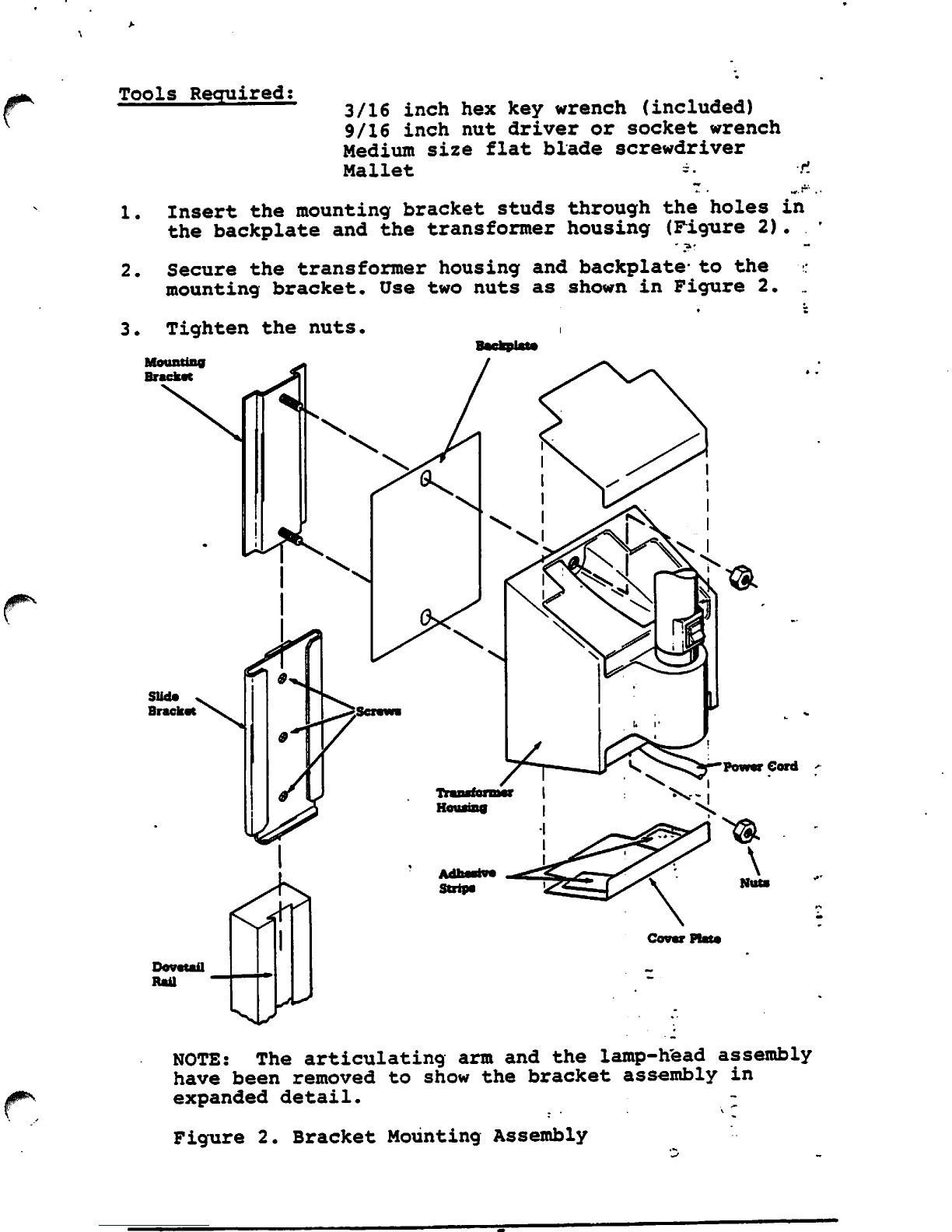
6.
Loosen
the
screws
on
the
slide
bracket
so
that
the
bracket
fits
into
the
dovetail
rail
(Figure
2).
7.
Slide
the
slide
bracket
into
the
rail
and
position
it.
^%
Firmly
tighten
the
screws
to
secure
the bracket
(Figure
l
2)..
page
6