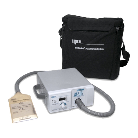
Ohmeda Giraffe Spot PT Lite Manual

Giraffe® Spot PT Lite™
Phototherapy System
Operation, Maintenance and Service Manual

User Responsibility
This Product will perform in conformity with the description thereof contained in this
operating manual and accompanying labels and/or inserts, when assembled, operated,
maintained and repaired in accordance with the instructions provided.This Product must
be checked periodically. A defective Product should not be used.Parts that are broken,
missing, plainly worn, distorted or contaminated should be replaced immediately. Should
such repair or replacement become necessary, Ohmeda Medical recommends that a
telephone or written request for service advice be made to the nearest Ohmeda Medical
Regional Service Center.This Product or any of its parts should not be repaired other
than in accordance with written instructions provided by Ohmeda Medical and by
Ohmeda Medical trained personnel.The Product must not be altered without the prior
written approval of Ohmeda Medical’s Quality Assurance Department.The user of this
Product shall have the sole responsibility for any malfunction which results from improper
use, faulty maintenance, improper repair, damage, or alteration by anyone other than
Ohmeda Medical.
CAUTION wU.S Federal law restricts this device to sale by or on the order of a licensed medical
practitioner.
Ohmeda Inc has declared that this product conforms with the European Council Directive
9 /42/EEC Medical Device Directive when it is used in accordance with the instructions
provided in the Operation and Maintenance Manual.
0086

i6600-0 61-000 08/10/02 i
General Information
The Light Source Unit ..................................................................................................1-1
The Gooseneck ...........................................................................................................1-1
Controls, Indicators and Connections..........................................................................1-2
Set Up and Checkout
Mounting the unit .........................................................................................................2-1
Pre-Use Checkout Procedure......................................................................................2-1
Operation
Basic Operating Procedure..........................................................................................3-1
Maintaining the unit
Repair Policy................................................................................................................4-1
Maintenance schedule.................................................................................................4-1
Cleaning.......................................................................................................................4-2
Replacing the fan filter .................................................................................................4-3
Replacing the bulb .......................................................................................................4-3
Accessories .................................................................................................................4-4
Service
Functional Description .................................................................................................5-1
Troubleshooting ...........................................................................................................5-2
Service Procedures .....................................................................................................5-3
Illustrated Parts............................................................................................................5-5
Labels ..........................................................................................................................5-9
Wiring Diagrams ........................................................................................................5-11
Appendix
Specifications............................................................................................................. A-1
Table of Contents

ii 6600-0 61-000 08/10/02 ii
Next to each warning or caution, we have placed an attention, read accompanying
documents symbol to alert you to the presence of these important statements. When the
attention symbol appears in front of the text that is printed on the system itself, it means
that the text is elaborated upon in the operation manual.
WARNING: A Warning statement is used when the possibility of injury to the patient or
the operator exists.
CAUTION: A Caution statement is used when the possibility of damage to the equipment
exists.
High voltage, electrical shock hazard.
Hot surface, do not touch.
Indicates alternating current.
Indicates IEC Type B equipment.
European Union Representative
Note: A Note provides additional information to clarify a point in the text.
WARNINGS w
Do not use the Giraffe®Spot PT LiteTM Phototherapy System in the presence of flam-
mable anesthetics or gases which can support combustion; a possible explosion hazard
exists under these conditions.
CAUTIONS w
Servicing of this product in accordance with the service manual should never be under-
taken without the proper tools, test equipment and the most recent revision of the service
manual which is clearly and thoroughly understood.
Definitions
m
~
w

General Information
1-1 6600-0 61-000 08/10/02 1-1
The Giraffe®Spot PT LiteTM Phototherapy System provides a
cool light for the treatment of hyperbilirubinemia.The system
consists of two main components: a light source unit which
houses the lamp, controls, universal power supply, cooling
system and thermostat; and the adjustable gooseneck which
contains the light pipe and lens that deliver therapeutic light
energy to the patient.
The Light Source Unit
A metal halide bulb provides the light source. A fan cools the
bulb and extends bulb life.
Located on the front of the unit, a rocker switch turns power on
and off. Located near the power switch, a non-resettable hour
meter shows how long the unit has been operated. Next to the
hour meter, a green LED indicator lights when the unit is on,
while a red LED indicator lights when the fan fails to operate
correctly or the unit overheats.
Underneath, on the base of the unit are the IEC power recep-
tacle, two resettable circuit breakers and the fan filter retainer. A
mounting bracket on the back of the unit allows the unit to be
positioned and secured in the dovetail slot of an accessory rail.
Tightening two socket head mounting screws holds the unit in
position.
The Gooseneck
The light intensity delivered to the patient varies directly with the
distance of the lens head from the mattress.You change the
intensity and spot size by manually adjusting this distance.The
vinyl coated flexible gooseneck allows the lens to be positioned
anywhere you wish; the gooseneck bends to a new position and
then holds the lens in place.A flexible light pipe inside the
gooseneck transmits the light from the lamp to the lens, where it
can be directed at the patient.
CI. 8.007

General Information
1-2 6600-0 61-000 08/10/02 1-2
Controls, Indicators
and Connections
1. Lens head
2. Gooseneck
3. Light Source Unit
4. Air exhaust
5. Power switch
6. Hour meter
7. Power indicator
8. Air flow failure indicator
9. Power cord receptacle
10. Circuit breakers
11. Air intake/fan filter retainer
1
2
34
5
6
7 9
10
11
CI. 8.00
CI. 8.004

Set up and Checkout
2-1 6600-0 61-000 08/10/02 2-1
CAUTION wTo avoid damage to equipment, install
bulb before powering unit.
Mounting the unit
1. Using the hex key provided with the unit, loosen the two
mounting screws on the side of the mounting bracket
2. Position the light source unit on the accessory dovetail rail.
3. Secure the unit in place by tightening the two mounting
screws with the hex key.
Pre-use Check Out Procedure
1. Examine the power cord, gooseneck, and light source unit
for obvious signs of damage.
2. Check that the light source unit is securely attached to the
accessory dovetail rail.
3. Move the gooseneck back and forth and up and down and
verify that it moves freely and stays in position.
4. Connect the power cord to an appropriate power source.
5. Select “|”on the power switch to turn the power on.The
power LED indicator will light.
Note: Immediately after turning the unit on, it takes several
seconds for the light to be emitted from the lens head. If
the light does not come on, switch off the unit, wait about
ten seconds and switch it back on.
6. Position the lens head so that the spot is on the center of
the bed.
1
2
3
1. Mounting bracket
2. Mounting screws
3. Dove tail rail
CI. 8.01

Set up and Checkout
2-2 6600-0 61-000 08/10/02 2-2
Notes

Operation
-1 6600-0 61-000 08/10/02 -1
WARNINGS wProlonged exposure to this light may harm the
unprotected eyes of the infant or the operator. For
safety, cover the infant’s eyes and avoid looking
directly at the light.
wThe bilirubin levels of infants receiving photo-
therapy should be regularly measured.
wPorphyrins are the by-products of the photochemi-
cal break down of the bilirubin molecule. In some
cases, exposure of porphyrins to phototherapy may
result in a localized reddening of the infant’s skin.
Therefore, skin assessment is indicated with all
types of phototherapy.
wLight can adversely affect drugs and other infusion
liquids. When using intravenous delivery systems
during phototherapy, shield any tubing with alumi-
num foil.
wWhen using the Giraffe Spot PT LiteTM Phototherapy
System with a radiant warmer, make sure the lens
head is not directly in the path of the radiant heat
rays, since this will block heat to the infant and may
damage the lens head.
wThe use of phototherapy equipment may raise the
patient’s temperature in a radiant warmer. The
patient’s temperature should always be monitored
while using phototherapy equipment.
wPhototherapy light is a form of radiant energy and
can raise the temperature inside an incubator’s
infant compartment.The patient’s temperature
should always be monitored while using photo-
therapy equipment.
wThe radiant energy from phototherapy lights can
increase an infant’s insensible water loss.Take
appropriate measures to maintain the patient’s fluid
balance while administering phototherapy.
wWhen using phototherapy equipment with radiant
warmers or incubators use the baby skin tempera-
ture mode (servo) unless manual mode is specifi-
cally prescribed. While both modes require patient
monitoring, the manual mode requires constant
attention. In the manual mode, you must take the
responsibility for detecting changes in the environ-
ment (drafts, direct sunlight, phototherapy light
usage, etc.) and the patient condition requiring
heater or lamp adjustments in response to these
changes. In the baby (servo) mode, the warmer or
incubator automatically adjust heat output to
maintain the desired skin temperature, reducing
(but not eliminating) the need to monitor the patient
and make adjustments to the equipment.

Operation
-2 6600-0 61-000 08/10/02 -2
CAUTIONS wTo avoid the device overheating, do not block
any of the vents on the light source unit and do
not operate the Giraffe Spot PT Lite Photo-
therapy System if the cooling fan is not working.
It is suggested that the Giraffe Spot PT Lite be checked with the
BilliBlanket®Meter for desired therapeutic intensity before use with
each patient.
1. Connect the power cord to an appropriate power source.
2. Select “|”on the power switch to turn the power on.
Note: Immediately after turning the unit on, it takes several seconds
for the light to be emitted from the lens head. If the light does not
come on, switch off the unit, wait about 10 seconds and switch it
back on.
3. Aim the light to the desired area.
4. Adjust to the desired spot size by raising or lowering the lens head.
D
H
A
Distance from lens Spot Diameter Surface Area Nominal irradiance
head to bed surface level (µW/cm2/nm)
HDA
8 cm 20.0 cm 14.2 cm25.0
50 cm 25.9 cm 526.8 cm222.5
60 cm 1.5 cm 779. cm215.0
70 cm 6.5 cm 1046. cm210.5
80 cm 42.0 cm 1 85.4 cm206.5
WARNING wDo not operate the lamp at a distance less than 38 cm from the patient.
CI. 8.011
CI. 8.007
Note: Since the Giraffe Spot PT Lite transmits very little heat
energy, it should not damage the clear hood of an Ohmeda Medical
incubator, even if it is in direct contact with the hood.
The table below lists nominal phototherapeutic irradiance intensity
levels when the lens head is positioned at various heights over the
bed surface.The light intensity listed is an average of readings
taken at 5 points within the light spot: measured in the center of the
spot and in the center of the 4 quadrants.
1
2
3
4
5
D
CI. 8.016

Maintaining the unit
4-1 6600-0 61-000 08/10/02 4-1
Repair Policy
Warranty repair and service must be performed by an Ohmeda
Medical Service Representative or at the Ohmeda Medical
Service and Distribution Center.To contact an Ohmeda Medical
Service Representative, call the your Ohmeda Medical Service
Office listed on the back cover.
Do not use malfunctioning equipment. Make all necessary
repairs or have the equipment repaired by an Ohmeda Medical
Service Representative. Parts listed in the service manual for
this product may be repaired or replaced by a competent,
trained person who has experience in repairing devices of this
nature.After repair, test the equipment to ascertain that it
complies with the published specifications.
CAUTION wDetailed information for more extensive
repairs is included in the service manual solely
for the convenience of users having proper
knowledge, tools and test equipment, and for
service representatives trained by Ohmeda
Medical.
Maintenance schedule
The unit should be maintained in accordance with the proce-
dures detailed in the Service Manual. Service maintenance must
be performed by a technically competent individual.
Operator maintenance
This schedule lists the minimum maintenance frequencies.
Always follow hospital and local regulations for required mainte-
nance frequencies.
Weekly or After Each Patient
Clean the Giraffe Spot PT Lite Phototherapy System. Disinfect
the unit if required or after use with infectious patients.
Quarterly
Inspect the air filter and clean or replace as required.
Note: This is the minimum inspection frequency.The filter must
be cleaned or replaced whenever it appears dirty.

Maintaining the unit
4-2 6600-0 61-000 08/10/02 4-2
Service maintenance
This schedule lists the minimum maintenance frequencies. Always
follow hospital and local regulations for required maintenance
frequencies.
As Required
It is recommended that the bulb be replaced after 2500 hours of use.
Annually
Perform the electrical safety procedure.
Check light intensity as described in the Service Section.
Cleaning
WARNINGww
ww
wNever use flammable cleaning solutions to
clean the Spot PT Lite.
Unplug the power cord and allow the unit to cool at least 10 minutes.
CAUTION ww
ww
wThe lens should only be cleaned with 70% isopro-
pyl alcohol and a lint-free soft cloth. Bleach must
not be used to clean the lens or any surrounding
area where the bleach may come into contact with
the lens.
Clean the outside of the light source unit and gooseneck using a
mild detergent solution. Aqueous solutions which are both hospital
disinfectants and microbactericides may be used. Do not allow
liquids to seep into the housing. Apply the cleaning solutions with a
clean cloth or sponge. Always dry the parts with a clean damp soft
cloth to avoid scratches and remove cleaner residue.
The following lists some cleaning solutions that may be
used safely:
Generic Formulation Maximum
Concentration Level
Glutaraldehyde 2%
Hydrogen Peroxide 6%
Iodophor Solution 0.27%
Cavicide 100% spray
Cleaning or replacing the fan filter
1. Disconnect power to the unit.
2. Unsnap the filter retainer from the bottom of the fan.
3. Inspect filter (6600-0236-850). Clean by rinsing in water or
replace if necessary.The filter retainer is keyed, with one
tab smaller than the other 3, to aid in correctly aligning the
retainer. Fan filter retainer
CI. 8.004

Maintaining the unit
4- 6600-0 61-000 08/10/02 4-
Replacing the bulb
It is recommended that the bulb be replaced after 2500 hours of
use.
WARNINGwTo ensure the proper operation and light
intensity, replace the bulb only with an
Ohmeda Medical bulb (6600-0235-850). Use of
other bulbs will affect the performance of,
and may result in damage to, the Giraffe Spot
PT Lite Phototherapy System.
1. Turn off power and disconnect the power cord. Allow the
lamp to cool at least 10 minutes.
WARNINGwWhen the unit is connected to a power
source, there is high voltage in the bulb
assembly. Always disconnect the power cord
when replacing the bulb.
2. Using a 3mm hex key (6600-1246-400), remove the screw in
the front of the unit, located in the center at the top of the
cover. Remove the cover.
3. Grasp the bulb assembly by the electrical connector and pull
it free from the wire retainer that holds it in place.
Note: Do not touch the center glass bulb or mirror with your
fingers. Contamination of the bulb may result in reduced
lamp performance. If you touch the bulb during installation or
if you see stains, clean the bulb with alcohol and dry with a
clean, soft cloth.
4. Disconnect the electrical connector and discard the bulb.
CAUTION wTo avoid damage to equipment, install bulb
before powering unit.
5. Connect the new bulb and slide it back into place. Orient the
bulb so that “THIS SIDE UP”faces up.Be sure that the bulb
seats completely in the groove in the metal housing.
6. Reinstall the cover and secure it with the screw. Never
operate the unit with the cover open.
I/0
I/0
CI. 8.005
CI. 8.006

Maintaining the unit
4-4 6600-0 61-000 08/10/02 4-4
Accessories
Power cords
NorthAmerica ...................................................................................... 6600-0775-603
IEC Plug............................................................................................... 6600-0592-062
U.K. ...................................................................................................... 6600-0574-603
C.E. ...................................................................................................... 6600-0574-612
Australian ............................................................................................. 6600-0574-613
Italian ................................................................................................... 6600-0574-615
Bulb ........................................................................................................... 6600-0235-850
Fan Filters (package of 12) ......................................................................... 6600-0236-850
Hex Key (fits cover and mounting bracket).................................................. 6600-1246-400
Hex Key Holder ........................................................................................... 6600-1247-400
Gooseneck Repair Tape.............................................................................. 6600-0258-850
Portable Roll Stand ..................................................................................... 6600-0894-216

Service
5-1 6600-0 61-000 08/10/02 5-1
Functional Description
The Giraffe Spot Phototherapy Lite consists of three printed circuit assemblies (PCA), several peripheral
components and an arc lamp. Power enters through an IEC 20 receptacle line filter assembly. The line filter,
along with a clamp-on ferrite bead that is located on the harness immediately after the line filter, provide
filtering of both the phase and neutral lines for compliance with various agency approvals. The phase and
neutral line then pass through circuit breakers for protection in the event of a device failure. After the circuit
breaker, the phase and neutral are connected to the power switch. The output of the power switch is con-
nected to the power supply PCA. The power supply is a universal input (90-264 VAC 50/60 Hz) switching
power supply. The supply outputs +12VDC + 5%. This voltage is not adjustable. The output of the power
supply is applied to the remaining two PCAs. The remaining two PCAs are the ballast and indicator board.
These two boards work interactively to properly light and monitor the operation of the bulb. A description of the
ignition and operation of the lamp follows below.
The bulb in this product is an arc lamp. To light the lamp a high voltage must be applied across the anode and
cathode of the lamp. Once the arc has occurred a low voltage but higher current will fully sustain the arc. The
energy input into the lamp causes the chemicals inside the lamp to excite causing them to emit a high intensity
light. The ballast converts the incoming 12 volts to a minimum 10.5 kilovolt pulses. The ballast s circuitry
detects the presence of an arc and then outputs 52 volts + 6 volts to the bulb. If no arc is detected, the
circuitry shuts down until power is cycled.
The ballast takes in a remote on/off control signal that is sent from the indicator board and outputs a lamp
status signal to the indicator board. The indicator board utilizes the on/off control line to turn off the lamp in the
event of an over-temperature condition. A remote off-board thermostat is used to sense when an over-
temperature condition occurs. The thermostat is normally closed and opens during an over-temperature
condition. In normal operation, the thermostat is closed, the over-temperature LED is off and the ballast
control signal is low (<0.5 volts), which turns the ballast on. In an over-temperature condition, the thermostat is
open, and the over-temperature LED signal to the ballast control is high (>2.7 volts), which turns off the ballast.
The lamp status signal from the ballast is converted to a 12 volt referenced signal to control the counting of the
hour meter. If a fault is detected by the ballast, or if the ballast is turned off due to over-temperature condi-
tions, the lamp status signal will go low, causing the hour meter to stop counting. A flashing hour glass on the
display of the hour meter indicates that the hour meter is counting. When in the stop counting mode, the
elapsed hours will be displayed, but the flashing hour glass will not occur.
Due to the large current (approximately 5 amperes) required by the ballast, the ballast and the indicator board
are connected in parallel to the power supply. The 12 volt supply for the hour meter and the two cooling fans is
passed directly through the indicator board. In addition the indicator board contains a power indicator LED.
When power is applied to the device regardless of the lamp status the power indicator will light, the fans will
operate, and the hour meter display will light.

Service
5-2 6600-0 61-000 08/10/02 5-2
Troubleshooting
Symptom Possible Problem Solution
Bulb does not light after Bulb is too hot for unit to switch on Allow bulb to cool for about 10 seconds and
switching unit off and reapply power. If left on fan will continue to
back on.Over temp operate and assist in cooling the bulb.
light doesn’t light.
Power light is lit.
Bulb doesn’t light Bad connection Check line voltage circuitry to power supply.
Over temp light Bad power switch Trace line voltage from line filter through circuit
doesn’t light. Power Bad circuit breaker breakers and power switch to power supply.
light doesn’t light. Bad line filter If line voltage is present going into any of these
devices but not present on the output of the
device, then replace that device.
Bad power supply If line voltage is present at power supply, verify
power supply output. 12 volts should be present
at J2 pins 1 referenced to pin 4. If there is no
output, replace power supply.
Bulb doesn’t light. Bad bulb Replace bulb.
Over temp light doesn’t Bad ballast Replace ballast*.
light. Power light is lit,
or
Arcing sound heard but
bulb does not light
Bulb doesn’t light or goes Dirty filter Unit is in overheat mode. Check fan inlet filter. out
every few minutes. Clean or replace filter if dirty.
Over temp light is lit Bad main or ballast fan Verify that both fans are running
or goes out when bulb lights Bad thermostat Thermostat can be tested with an ohm meter. In
Power light is lit. normal operation the thermostat should be
closed.
Bulb lights but Power light Bad indicator board Replace indicator board.
doesn’t light. Over temp
light doesn’t light.
Low light output Lens blocked. Clean lens.
Bad bulb. Replace bulb.
Bad ballast Replace ballast*.
Hour meter doesn’t display Bad hour meter Verify that 12 volts is present on J3 pins 2
hours.Power light is lit. referenced to pin 4. If voltage is present replace
hour meter.
Hour meter doesn’t count Bad indicator board Verify that >11 volts is present on J3 pins 1
hours when bulb is on. Bad hour meter referenced to 4. If voltage is present replace Power
light is lit. Bad ballast hour meter. If voltage is less than 11 volts verify
that voltage at J1 pin 4 referenced to pin 5 is
>1.421 volts. If voltage is present replace
indicator board. If voltage is not present,
replace ballast*.
*Due to the dangerous high voltage pulses and internal testing circuitry in the ballast, testing of the output is not recommended. Replac-
ing the bulb with a known good bulb is recommended to determine if the problem is with the bulb or the ballast.

Service
5- 6600-0 61-000 08/10/02 5-
Service Procedures
Light Intensity Check
Turn on the light and wait a minute until the lamp stabilizes. Focus the light so that the spot diameter is 20.0 cm
(about 8 cm from the bed surface). Using the BiliBlanket Meter, measure the light at the 5 points indicated on
the diagram and average the 5 readings. It should be approximately 0-40 µW/cm2/nm for a new bulb. The
absolute minimum for a new bulb is 25 µW/cm2/nm.
Note: Bulbs have a typical intensity degradation of approximately 10% over their lifespan.
Note: After performing any repair always perform the Light Intensity Check.
WARNINGS wThe design of this product incorporates ultraviolet and infrared filters. During servic-
ing, never look directly at the lamp. Exposure for a duration of 10 minutes can cause
eye damage. During troubleshooting proper eye protection should be worn.
wThe design of this product utilizes both covers to provide proper cooling of the lamp
and circuitry. Operation of the unit for a duration of more than 10 minutes can cause
overheating of the lamp and circuitry, which could damage the device.
wDue to the high pressures inside the lamp improper cooling could cause the lamp to
shatter. Both covers should be installed prior to applying power. During trouble-
shooting proper eye protection should be worn.
Opening the Light Source Enclosure (See Figure 5-1)
1. Disconnect the unit power cord from the wall outlet or equipment that it is plugged into.
2. Using the mm hex key provided with the unit, remove the screw in the front of the unit, located in the
center at the top of the front cover. Remove cover.
. Use a 7mm nutdriver or socket to loosen the nut that secures the sheet metal EMI shield. Slide the EMI
shield up and out of the unit.
Disassembling the gooseneck (See Figure 5-2)
1. Remove the front cover and EMI shield.
2. To remove the gooseneck, remove the retaining ring and telflon washer located inside the bulb bracket and
teflon washer on the top unit, then remove the gooseneck from unit.
. To remove the lens head from the gooseneck, remove the retaining ring just inside the lens housing and
slide the housing back up the gooseneck, so that you can see the entire lens retainer, which is the plastic
sleeve inside the lens housing.
4. Spread the back of the lens retainer out to release it from the groove in the end of the gooseneck and remove it.
5. To remove the lens, spread the front of the lens retainer and carefully remove the lens.
Note: When replacing the convex lens, it is important that the arrow on the side of the lens face towards the
main unit. Care should be taken when handling the lens to keep finger oils and fingerprints off the lens
surfaces. Lens may be cleaned with 70% isopropyl alcohol and a lint-free soft cloth.
1
2
3
4
5

Service
5-4 6600-0 61-000 08/10/02 5-4
Replacing the Bulb Bracket and Thermostat (See Figure 5- )
1. Remove the front cover, EMI shield, gooseneck and bulb.
2. Use a 7mm wrench to remove the screws that secure the bracket.
. Pop the seal out of its groove. To remove the mirror, use a 2mm hex key to remove the 2 screws that hold
it in position.
4. To remove the thermostat, disconnect its connector from J4 on the LED board.
5. Cut the 2 cable ties that secure the thermostat to the cable tie holder and remove the thermostat. If you
are replacing the thermostat, remember to order 2 new cable ties to hold it in position.
6. Remove the wire bulb retainer by removing the nut that secures it on the mounting stud. When replacing
or reinstalling the bulb retainer, position it from 0.45 to 0.5 inches from the bulb bracket to maintain ad-
equate spring load on the bulb.
Replacing the Ballast (See Figure 5- )
WARNING wShock hazard. The ballast emits high voltage pulses. Disconnect the unit from power
source and use extreme care when servicing it. It is not recommended to measure the
voltages at the lamp: this may damage measuring equipment.
1. Disconnect all the wire harnesses coming from the ballast.
2. Disconnect the bulb connector from the bulb.
. Cut the cable tie strain relief. Order a new cable tie (6600-0 84-400) when you replace the ballast.
4. Using a 2mm hex key, remove the 4 M screws that secure the ballast and remove the ballast.
Removing other components (See Figure 5-5 and 5-6)
To replace the components located in the lower portion of the unit it is necessary to first remove the large U
shaped bracket at the bottom of the unit. To remove the bracket use a 7mm wrench to remove the 2 nuts that
hold the bracket to the back cover. It may be necessary to carefully move or remove ballast fan bracket to
access the other components.
Power Supply- To remove the power supply, first disconnect its wire harness, then use a Phillips head screw-
driver to remove the 4 screws that secure it to the back cover.
Main Fan-To remove, first remove the fan guard and filter from the bottom of the unit, then disconnect the fan
from J2 on the LED board. Use a Phillips head to turn the 4 screws and a 5.5mm wrench to hold the 4 nuts
that secure it to the U bracket.
Indicator Board- To remove the LED Board, first disconnect the boards wire harnesses, then pop the board
off its standoffs.
Circuit Breakers- to remove the circuit breakers disconnect their wire harnesses then unscrew the knurled nut
that holds them to the U bracket.
Power Switch, Line Filter and Hour Meter- To remove any of these components simply disconnect their wire
harnesses and pop them out of their cutout in the U bracket. The line filter is secured by two screws.
When removing the power switch, you must also remove its clear plastic drip cover. When replacing the
hour meter, you must also replace its label on the front cover.

Service
5-5 6600-0 61-000 08/10/02 5-5
Illustrated Parts
1
2
3
4
5
6
7
10
9
1. Light pipe retaining ring ........................... 6600-1257-400
2. Teflon washer .......................................... 6600-1256-400
. Indicator board ........................................ 6600-0251-850
4. EMI housing cover .................................. 6600-0249-850
5. Push nut, M4 ........................................... 6600-0881-400
6. Cover (includes items 5 & 7) ................... 6600-0250-850
7. Screw, M4 x 60L ...................................... 6600-0707-450
8. Power cord retainer ................................. 6600-1701-500
9. Washer, M ............................................. 6600-0712-402
10. Split ring washer, M ............................... 6600-071 -402
11. Screw, Skt. Hd. M x 10 .......................... 6600-0707-40
12. Star washer, M4 ...................................... 6600-071 -4 2
1 . Nut, M4 .................................................... 6600-0711-407
14. Label, ground .......................................... 0205-47 7- 00
15. Washer, M4 ............................................. 6600-0712-40
Figure 5-1
Outside covers
2
11
14
12, 13
13
12
1213
15
CI.38.021

Service
5-6 6600-0 61-000 08/10/02 5-6
1. O-ring ...................................................... 6600-12 2-400
2. Light pipe (include 2 pcs of item 1 O-ring) . 6600-0252-850
. Lens cover ............................................... 6600-1575-500
4. Lens retainer ........................................... 6600-1574-500
5. Lens ........................................................ 6600-2010-500
6. Retainer ring ............................................ 6600-1225-400
Figure 5-2
Goosneck
11
2
3
4
56
1. Bulb ......................................................... 6600-02 5-850
2. Bulb retainer ............................................ 6600-1549-500
. Washer, M4 ............................................. 6600-0712-40
4. Split ring washer, M4 ............................... 6600-071 -40
5. Nut, M4 .................................................... 6600-0711-407
6. Cable tie holder ....................................... 6600-12 0-400
7. Power supply ........................................... 6600-0840-600
8. Washer, M ............................................. 6600-0712-402
9. Washer, lock M int. tooth ....................... 6600-071 -4 1
10. Screw, M x 10 Skt HD ........................... 6600-0707-40
11. Thermostat assembly .............................. 6600-1067-700
12. Cable tie .................................................. 6600-0 84-400
1 . Star washer, M ...................................... 6600-071 -4 1
14. Ballast assembly ..................................... 6600-0248-850
15. Standoff, M x 19L .................................. 6600-1224-400
Figure 5-3
Bulb, power supply, thermostat and ballast
1
2
345
6345
7
9
10
11
12
13
14
15
10
CI.38.020
CI.38.019
Table of contents
Other Ohmeda Medical Equipment manuals
Popular Medical Equipment manuals by other brands

Getinge
Getinge Arjohuntleigh Nimbus 3 Professional Instructions for use

Mettler Electronics
Mettler Electronics Sonicator 730 Maintenance manual

Pressalit Care
Pressalit Care R1100 Mounting instruction

Denas MS
Denas MS DENAS-T operating manual

bort medical
bort medical ActiveColor quick guide

AccuVein
AccuVein AV400 user manual