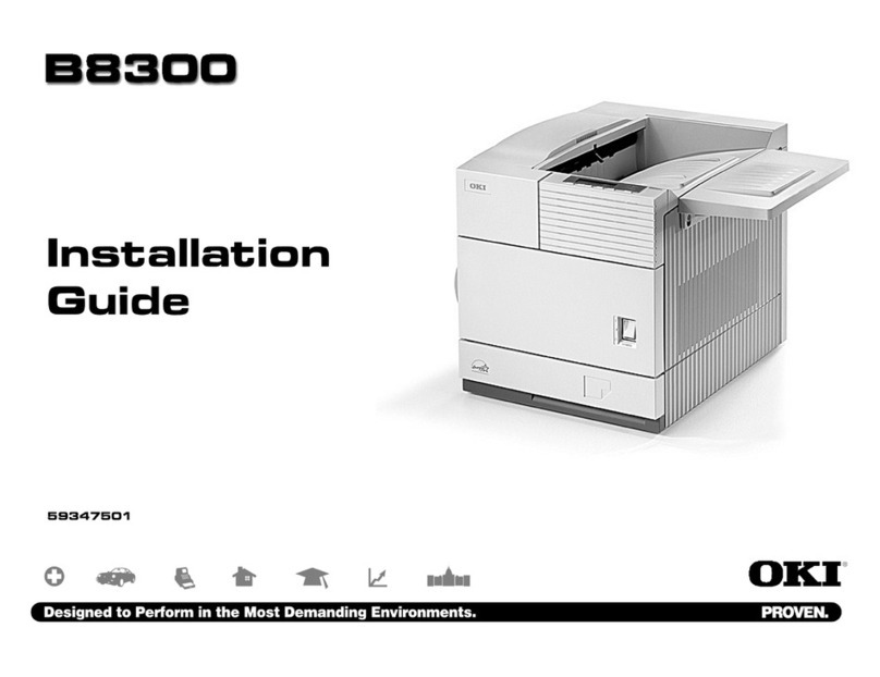
Oki B6500 Series User manual

Laser Printer
OKI B6500
Service Manual
060810A

i
Cautions For Operation
Contents of this document may be subjected to modification without previous notice.Oki Data
will not assume any responsibilities for accidental or incidental damages
resulting from technical or editorial errors or omission in this manual, issue of this manual,
execution of description in this manual, or use of this manual.
This document is protected by copyright. It is not forgiven to photocopy or duplicate any part
of this document in any form without previous permission in writing from Oki Data, Americas, Inc.

ii
1. About This Manual
This manual is a standard service manual containing information required for maintenance
of this laser printer (standard specifications).
2. Cautions, Warnings and Notes
Maintenance operations requiring special cautions or additional information for procedures
in this manual are presented as "Warning", "Caution", or "Note", according to their nature.
If instructions are not observed, death or serious injury may be caused.
If instructions are not observed, personal injury or physical damage to assets
(including this laser printer) may result.
Particularly important essentials for procedures, steps, rules, etc.
Reference Incidental information to descriptions.
3. Related documents
TInstruction manuals (standard manuals)
Describe operation and handling of this laser printer.
TPerformance specifications
Describe in detail various specifications of this laser printer.
(In the event of discrepancy between this manual and the performance specifications, the
performance specifications shall take preference.)
TVideo interface specifications
Detailed video interface specifications for this laser printer
TSpare parts list
Information on maintenance parts (spare parts) for this laser printer

iii
4. Safety
To prevent possible accidents during maintenance activities, you must pay attention to the
"Warning" and "Caution" information in this manual.
Performing any dangerous operations, or procedures not included in this manual, should be
avoided.
Occasionally, it may be required to perform some procedures not covered by this manual.
These procedures should be performed carefully, always giving attention to safety.
4.1 Power source
Keep the power supply off during maintenance activities to prevent electric shock,burns and
equipment damage. Keep the power plug disconnected during the maintenance operation.
If it is necessary for the machine power to be switched ON for voltage measurements or
other similar reasons, sufficient care should be given to prevent electric shock, by following
the procedures in this manual.
While the printer is ON, never touch live components.
Power is supplied to the power unit (LVPS ASSY) even while the printer is off.
Never touch its live components.
Do not touch live components unless otherwise specified.
J20101AA

iv
4.2 Drive units
When servicing gears or other drive units, be sure to turn them OFF and disconnect the
power plug from the receptacle. Whenever possible, drive them manually.
Never touch the gears or other moving parts while the printer is running.
4.3 High-temperature units
When servicing high-temperature units (removal, replacement, adjustment, etc.), be sure to
turn them OFF to prevent burns, injuries and an electrical hazard. Remove the power plug
from the receptacle and allow the unit to cool down before servicing.
Fusing units retain their heat after the power is removed. Wait at least 30 minutes
after removing power before servicing.

v
4.4 Laser beams
• Direct exposure to a laser beam can damage the eyes and cause blindness.
• Never open a cover that has a laser warning label attached.
• Before disassembling and reassembling this laser printer, be sure to turn the
printer power OFF.
• When servicing this laser printer while it is running, be sure to follow the
procedures specified in this manual.
• You should understand and exercise all safety precautions to prevent injuries
when servicing equipment that uses a laser. Carefully follow procedures to
prevent anyone in the area from exposure to the laser beam.
Laser beams have the following characteristics:
• Frequencies are higher than other beams (sun and electric bulbs) and
phases are uniform so that high monochromatic and convergence performance
can be obtained and thin beams of light can reach places at a long distance.
• Due to the high convergence, beams are highly concentrated in density and
temperature, which is dangerous to human body.
Reference: The frequency of the Laser used in this laser printer produces beams that are
invisible.

vi
4.5 Warning/caution labels
Warning labels and caution labels are attached to this laser printer to prevent accidents.
These labels should be clear and easy to read. Check the labels for any damage such as
peeling or stains when servicing the printer.
4.5.1 Caution label for high-temperature units
4.5.2 Caution label for laser beams
Hi Temp Label
Laser Beam Label

vii
5. Installation
5.1 Power source
Do not plug too many leads into a single socket. Use a dedicated electric outlet and
confirm that the power is within specifications.
Connect the single power cord to an electric outlet capable of supplying more
power than the maximum power consumption of this laser printer.
5.2 Ground
Be sure the laser printer is properly grounded.
Be sure to connect the ground of this laser printer with one of the following:
- Grounding terminal of an electric outlet
- Copper or the like which is embedded 650 mm or deeper in the ground
- Grounding terminal for which the grounding work has been carried out
Be sure not to establish a ground with the following:
- Gas pipe
- Ground for telephone
- Water pipe which is partially made from plastic
When establishing a ground, be sure not to use the 2pin - 3pin conversion plug.
5.3 Installation location
• Ensure that there is adequate space for operating this printer.
• Install where the temperature and the humidity meet the following environmental
specifications:
During operation:
5 to 35 degree C / 15 to 85% RH (70% RH at 35 degree C, 85% RH at 32
degree C).
No condensation
Not in operation:
-20 to 40 degree C / 5 to 85%
RH (A place with no condensation)
• Install in a flat place with the angle of 5 degrees or less.
• Install in a place with the illumination of 3000 Lux or less. (Avoid direct sunlight.)
• Avoid placing near a water system, a humidifier or fire, a dusty place, or a place
which gets direct air from air conditioning.
• Avoid where volatile or flammable gas is generated.
• Avoid a poor ventilated place.
• Avoid an unstable and non-durable place.

viii
5.4 Unpacking
5.4.1 Unpacking laser printer
The printer must be carried horizontally with two or more persons.
Extreme care must be taken to avoid personal injuries.
Unpack the carton and confirm that the part numbers of the laser printer and all
components are correct. Ensure that all components are without damage.
1) Laser Printer main unit
2) 150 Paper Cassette
3) 550 Paper Cassette
4) EP CARTRIDGE
5) Power Cord
6) Instruction Manual
5.4.2 Unpacking Option Duplex
Unpack the carton and confirm that the part numbers of the Duplex Transport and all
components are correct. Ensure that all components are undamaged.
1) Option Duplex main unit
J20009A

ix
5.4.3 Unpacking Option Face Up Tray
Unpack the carton and confirm that the part numbers of the Face Up Tray and all
components are correct. Ensure that all components are undamaged.
5.4.4 Unpacking Option 550 Paper Feeder
Unpack the carton and confirm that the part numbers of the Option 550 Paper Feeder
and all components are correct. Ensure that all components are undamaged.
1) Option 550 Paper Feeder main unit
2) Option 550 Paper Cassette
3) JOINT FEEDER (four pieces)
JG0008AA
J20007AA

x
5.5 Installation Procedures
5.5.1 Installing laser printer
For details, refer to the Instruction Manual supplied with the main unit.
When holding up the later printer, be sure to grasp the handles with both hands.
Grasping a part other than the handles result in fall or damage of the laser printer.
When holding up the later printer, bend your knees thoroughly to prevent lower
back strain.
The protection sheets and the fixing materials, which are removed before the
installation, are re-used when the later printer is moved to another place. Be sure to
keep them.
1) Unpack the laser printer, and place it in an installation location after removing
cushioning materials.
2) Confirm the attachments.
3) Peel off fixing tapes applied to the later printer.
4) Unpack the EP CARTRIDGE, then be sure to shake it seven to eight times holding
both sides.
When removing the toner seal, draw it out straight and horizontally. After
removal, be careful not to shake or give a shock to the EP CARTRIDGE.
5) Open the COVER OPEN, and install the EP CARTRIDGE.
6) Close the COVER OPEN.
7) Draw the paper tray, and press down the PLATE ASSY BTM to lock.
8) Place papers into the paper tray.
When placing papers into the paper tray, be careful for the followings:
- Align four corners of papers to place.
- Adjust the paper guide to the paper size.
- Do not place papers over the capacity or over the upper-limit line of the paper
tray.
9) Push the paper tray into the laser printer to install.
10) Connect the power cord.
11) Turn on the power switch of the laser printer.
12) Try some test printings with each paper-feed trays to confirm that there is no
problem.

xi
5.5.2 Installing Option Duplex
For details, refer to the InstructionManualsupplied withthe main unitor Chapter 3 RRP
21.1 Option Duplex.
Before the installation, turn off the power and plug off the power cord.
1) Unpack the Option Duplex, remove cushioning materials, and confirm that all
attachments are available.
2) Remove the COVER DUP and CONNECTOR COVER on rear of the laser printer.
Keep the removed COVER DUP and CONNECTOR COVER carefully.
3) Fit the hooks on the lower part of the Option Duplex with the holes on the rear of
the laser printer to install.
4) Tighten the screws (two) on the lower part of the Option Duplex to fix securely.
5) Connect the power cord.
6) Turn on the power switch of the laser printer.
7) Try some test duplex-printings to confirm that there is no problem.
5.5.3 Installing Option Face Up Tray
For details, refer to the Instruction Manual supplied with the main unit.
Before the installation, turn off the power and plug off the power cord.
1) Unpack the Option Face Up Tray, remove cushioning materials, and confirm that all
attachments are available.
2) Insert the front edge of the Option Face Up Tray into the slot on the upper-rear of the
laser printer to install.
3) Connect the power cord.
4) Turn on the power switch of the laser printer.
5) Try running some test prints to eject onto the Option Face Up Tray and confirm that
there are no problems.

xii
5.5.4 Installing Option 550 Paper Feeder
For details, refer to the InstructionManualsupplied withthe main unitor Chapter 3 RRP
20.1 Option 550 Paper Feeder.
Before the installation, turn off the power, plug off the power cord, and remove the
paper tray from the laser printer.
1) Unpack the Option 550 Paper Feeder, remove cushioning materials, and confirm
that all attachments are available.
2) Place the Option 550 Paper Feeder in an installation location.
3) Fit the holes on the bottom of the laser printer with the four positioning bosses of
the Option 550 Paper Feeder, and place the laser printer on the Option 550 Paper
Feeder.
4) Fix the laser printer and the Option 550 Paper Feeder securely with the JOINT
FEEDERs (four pieces).
5) Push the paper tray into the laser printer completely to install.
6) Connect the power cord.
7) Turn on the power switch of the laser printer.
8) Try some test printings withthe newly installed paper-feed tray toconfirm that there
is no problem.

xiii
6. Dismantlement
6.1 Dismantlement procedures
6.1.1 Dismantling laser printer and option units
For details, refer to the Instruction Manual or Chapter 3 Removal and Replacement
Procedures.
The dismantlement process is performed by following installation procedures in
reverse sequence.
When holding up the later printer, be sure to grasp the handles with both hands.
Grasping a part other than the handles results in fall or damage of the laser printer.
When lifting the later printer, bend your knees thoroughly to prevent lower back
strain.
Be sure to remove the EP CARTRIDGE from the laser printer and put it into a
plastic bag.
Be sure to re-use the protection sheets and fixing materials, which are removed
during the installation.
Confirm that no attachment is missing.
Be sure to use the cushioning materials properly.

xiv
Chapter 1 Troubleshooting.............................................................................................1 - 1
Chapter 2 Diagnostics................................................................................................... 1 - 1
Chapter 3 Removal and Replacement Procedures.........................................................3 - 1
Chapter 4 Print Engine Plug/Jack Connector Locations.................................................1 - 1
Chapter 5 Parts List........................................................................................................1 - 1
Chapter 6 Principles of Operation..................................................................................1 - 1
Chapter 7 Wiring.............................................................................................................1 - 1
Chapter 8 Printer Specifications.....................................................................................1 - 1
Chapter 9 ESS Options..................................................................................................1 - 1

xv
Blank Page

Chapter 1 Troubleshooting
Chapter 1 Troubleshooting CONTENTS
Chapter 1 Troubleshooting............................................................................................ 1 - 1
1. Progressing with the Troubleshooting........................................................................ 1 - 1
1.1 Troubleshooting Flow Chart............................................................................................................. 1 - 1
1.2 Preparatory Requirements............................................................................................................... 1 - 2
1.3 Cautions for Service Operations...................................................................................................... 1 - 3
1.4 Cautions for FIP Use........................................................................................................................ 1 - 4
2. Level 1 FIP ................................................................................................................. 1 - 6
2.1 Level 1 FIP....................................................................................................................................... 1 - 6
2.2 Flow of Level 1 FIP .......................................................................................................................... 1 - 6
2.3 Error/Status Code List...................................................................................................................... 1 - 7
3. Level 2 FIP ............................................................................................................... 1 - 10
3.1 Level 2 FIP..................................................................................................................................... 1 - 10
4. Error Code FIP ......................................................................................................... 1 - 11
4.1 Level 1 FIP..................................................................................................................................... 1 - 11
FIP1.1 NVM Error ................................................................................................................................ 1 - 11
FIP1.2 ROS Error................................................................................................................................. 1 - 12
FIP1.3 Fuser Error ............................................................................................................................... 1 - 13
FIP1.4 Fan Error.................................................................................................................................. 1 - 14
FIP1.5 Main Motor Error ..................................................................................................................... 1 - 15
FIP1.6 Cover Error............................................................................................................................... 1 - 16
FIP1.7 FIP Paper Jam/Regi to Fuser .................................................................................................. 1 - 17
FIP1.8 Paper Jam/Exit ........................................................................................................................ 1 - 20
FIP1.9 Paper Jam/Tray to Regi .......................................................................................................... 1 - 22
FIP1.10 Paper Jam/Misfeed ............................................................................................................... 1 - 24
FIP1.11 EP Cartridge .......................................................................................................................... 1 - 26
FIP1.12 Paper Size Error .................................................................................................................... 1 - 27
FIP1.13 No Tray/Tray 1, 2 .................................................................................................................. 1 - 28
FIP1.14 No Paper/Tray 1, 2................................................................................................................. 1 - 29
FIP1.15 Low Paper in Tray/Tray 2 ...................................................................................................... 1 - 30
FIP1.16 Drum Life ............................................................................................................................... 1 - 31
FIP1.17 Fuser Life .............................................................................................................................. 1 - 32
FIP1.18 No Power ............................................................................................................................... 1 - 33
FIP1.19 LCD/LED Display Error ......................................................................................................... 1 - 36
FIP1.20 Inoperative Keypad ............................................................................................................... 1 - 37
FIP1.21 Other Printer Error ................................................................................................................. 1 - 38
FIP1.22 Face Up Tray Error ................................................................................................................ 1 - 39
FIP1.23 Full Stack Error/500 Paper Exit ............................................................................................. 1 - 40
4.2 Level 2 FIP......................................................................................................................................1 - 41
FIP1.24 LVPS ..................................................................................................................................... 1 - 41
FIP1.25 MAIN MOTOR ....................................................................................................................... 1 - 42
FIP1.26 ROS ASSY ............................................................................................................................ 1 - 43
FIP1.27 FUSER ASSY ........................................................................................................................ 1 - 45
FIP1.28 SENSOR REGI ..................................................................................................................... 1 - 47
FIP1.29 SENSOR NO PAPER ............................................................................................................ 1 - 49
FIP1.30 SENSOR LOW PAPER ......................................................................................................... 1 - 51
FIP1.31 SENSOR TONER .................................................................................................................. 1 - 52
FIP1.32 INTERLOCK S/W 24V ........................................................................................................... 1 - 53
FIP1.33 INTERLOCK S/W 5V, SWITCH I/L ASSY ............................................................................. 1 - 54
FIP1.34 INTERLOCK S/W REAR ....................................................................................................... 1 - 55
FIP1.35 SWITCH I/L ASSY (Interlock S/W Front R) ........................................................................... 1 - 56
FIP1.36 PWBA EXIT MOTOR ............................................................................................................ 1 - 57

Chapter 1 Troubleshooting
Chapter 1 Troubleshooting CONTENTS
FIP1.37 MOTOR ASSY EXIT ............................................................................................................. 1 - 58
FIP1.38 CLUTCH REGI ...................................................................................................................... 1 - 59
FIP1.39 CLUTCH ASSY PH ............................................................................................................... 1 - 60
FIP1.40 GUIDE TRAY LEFT ............................................................................................................... 1 - 61
FIP1.41 HVPS/MCU ........................................................................................................................... 1 - 62
FIP1.42 Electrical Noise ...................................................................................................................... 1 - 63
FIP1.43 MOTOR ASSY EXIT ............................................................................................................. 1 - 65
FIP1.44 SENSOR FACE UP OPEN ................................................................................................... 1 - 66
FIP1.45 SENSOR FULL STACK ........................................................................................................ 1 - 67
Duplex Option ...............................................................................................................1 - 69
4.3 Error/Status Code List.....................................................................................................................1 - 69
4.4 Table 1............................................................................................................................................1 - 69
4.5 Level 1 FIP......................................................................................................................................1 - 70
FIP2.1 Option Duplex Cover Error ...................................................................................................... 1 - 70
FIP2.2 Option Duplex Error ................................................................................................................. 1 - 71
FIP2.3 Paper Jam/Exit to Dup ............................................................................................................ 1 - 72
FIP2.4 Paper Jam/Dup to Regi ........................................................................................................... 1 - 73
FIP2.5 Paper Jam/Duplex Misfeed ..................................................................................................... 1 - 74
FIP2.6 Paper Size Error/Duplex .......................................................................................................... 1 - 75
FIP2.7 No Recognition of Option Duplex ............................................................................................ 1 - 76
4.6 Level 2 FIP......................................................................................................................................1 - 77
FIP2.8 PWBA DUPLEX ...................................................................................................................... 1 - 77
FIP2.9 MOTOR DUPLEX .................................................................................................................... 1 - 78
FIP2.10 SENSOR DUP ....................................................................................................................... 1 - 79
FIP2.11 SWITCH DUPLEX ................................................................................................................. 1 - 80
OCT Option ..................................................................................................................1 - 81
4.7 Error/Status Code List.....................................................................................................................1 - 81
4.8 Level 1 FIP......................................................................................................................................1 - 82
FIP3.1 Option OCT Cover Error .......................................................................................................... 1 - 82
FIP3.2 Option OCT Error .................................................................................................................... 1 - 83
FIP3.3 Paper Jam/Exit to OCT ........................................................................................................... 1 - 84
FIP3.4 Paper Jam/OCT ...................................................................................................................... 1 - 85
FIP3.5 Paper Size Error/OCT ............................................................................................................. 1 - 86
FIP3.6 Full Stack Error/OCT ............................................................................................................... 1 - 87
FIP3.7 No Recognition of Option OCT ................................................................................................ 1 - 88
4.9 Level 2 FIP......................................................................................................................................1 - 89
FIP3.8 PWBA OCT ............................................................................................................................. 1 - 89
FIP3.9 MOTOR ASSY OCT ................................................................................................................ 1 - 90
FIP3.10 MOTOR ASSY OFFSET ....................................................................................................... 1 - 91
FIP3.11 SOLENOID ASSY GATE ...................................................................................................... 1 - 92
FIP3.12 S/W REAR COVER ............................................................................................................... 1 - 93
FIP3.13 SENSOR OCT ....................................................................................................................... 1 - 94
FIP3.14 Sensor Full Stack (On PWBA OCT) ...................................................................................... 1 - 95
FIP3.15 Sensor Offset (On PWBA OCT) ............................................................................................ 1 - 96
550 Paper Feeder Option .............................................................................................1 - 97
4.10 Error/Status Code List...................................................................................................................1 - 97
4.11 Level 1 FIP....................................................................................................................................1 - 98
FIP4.1 No Tray/Tray 3, 4 .................................................................................................................... 1 - 98
FIP4.2 No Paper/Tray 3, 4 .................................................................................................................. 1 - 99

Chapter 1 Troubleshooting
Chapter 1 Troubleshooting CONTENTS
FIP4.3 Low Paper in Tray/Tray 3, 4 .................................................................................................. 1 - 100
FIP4.4 No Recognition of Option 550 Paper Feeder ........................................................................ 1 - 101
FIP4.5 Inappropriate Option 550 Paper Feeder ................................................................................ 1 - 102
4.12 Level 2 FIP..................................................................................................................................1 - 103
FIP4.6 PWBA FEEDER 550 ............................................................................................................. 1 - 103
FIP4.7 PWBA FEEDER 550 ............................................................................................................. 1 - 104
FIP4.8 SENSOR NO PAPER ............................................................................................................ 1 - 105
FIP4.9 SENSOR LOW PAPER ......................................................................................................... 1 - 107
FIP4.10 OPT ASSY SIZE ................................................................................................................. 1 - 108
FIP4.11 CLUTCH ASSY PH ............................................................................................................. 1 - 109
FIP4.12 CLUTCH PR-REGI .............................................................................................................. 1 - 110
5. 5. Image Quality Defects........................................................................................ 1 - 111
5.1 Entry Chart for Image Quality Troubleshooting.............................................................................1 - 111
5.2 Image Quality FIP .........................................................................................................................1 - 113
FIP- 1.P1 Faint Print ......................................................................................................................... 1 - 113
FIP- 1.P2 Blank print (No print) ......................................................................................................... 1 - 115
FIP- 1.P3 Solid Black ........................................................................................................................ 1 - 117
FIP- 1.P4 Vertical blank lines (White stripes in paper transport direction) ........................................ 1 - 118
FIP- 1.P5 Horizontal band cross out ................................................................................................. 1 - 120
FIP- 1.P6 Vertical stripes .................................................................................................................. 1 - 122
FIP- 1.P7 Horizontal stripes .............................................................................................................. 1 - 123
FIP- 1.P8 Partial Deletion ................................................................................................................. 1 - 125
FIP- 1.P9 Spots ................................................................................................................................. 1 - 126
FIP- 1.P10 Ghosting ......................................................................................................................... 1 - 127
FIP- 1.P11 Background (Fog) ........................................................................................................... 1 - 129
FIP- 1.P12 Skew ............................................................................................................................... 1 - 130
FIP- 1.P13 Paper damage ................................................................................................................ 1 - 131
FIP- 1.P14 Unfused Image ............................................................................................................... 1 - 133
6. Judgment of Print Consistency................................................................................1 - 135
6.1 Leading edge registration ............................................................................................................ 1 - 135
6.2 Side Edge Registration................................................................................................................ 1 - 136
6.3 Skew ............................................................................................................................................ 1 - 137
6.4 Perpendicularity ........................................................................................................................... 1 - 138
6.5 Parallelism ................................................................................................................................... 1 - 139
7. Preventive Maintenance..........................................................................................1 - 141

Chapter 1 Troubleshooting
Chapter 1 Troubleshooting CONTENTS
Blank Page
Other manuals for B6500 Series
22
Table of contents
Other Oki Printer manuals