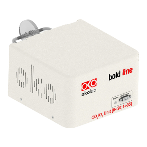
Okolab CO2-O2-UNIT-BL User manual

1
CO2-O2-UNIT-BL [0-20; 1-95]
Gas Controller
Manual
IST1335_REV01
SV 2.4.0.3048

2
This page was left Blank

3
Index
1PREFACE .....................................................................................................................................................................................4
2SYMBOL DESCRIPTION ..........................................................................................................................................................5
SYMBOLS USED IN THIS MANUAL...............................................................................................................................................................5
SYMBOLS ON THE PRODUCT LABEL ...........................................................................................................................................................5
3SAFETY NOTES..........................................................................................................................................................................6
4SUPPLIED EQUIPMENT..........................................................................................................................................................8
5GAS SUPPLIED REQUIREMENTS .........................................................................................................................................9
6COMPATIBILITY.................................................................................................................................................................... 10
7EQUIPMENT DESCRIPTION ............................................................................................................................................... 12
8INSTALLATION ...................................................................................................................................................................... 14
SETTING UP CO2-O2-UNIT-BL [0-20; 1-95].................................................................................................................................14
HOW TO ASSEMBLE CO2-O2-UNIT-BL [0-20; 1-95] WITH A BOLD LINE TCONTROLLER ....................................................21
9USER INTERFACE .................................................................................................................................................................. 23
HOME PAGE................................................................................................................................................................................................23
9.1.1 How to enter the Setpoint .......................................................................................................................................................23
9.1.2 Controller Status: colours led and meaning....................................................................................................................25
SETTINGS....................................................................................................................................................................................................26
9.2.1 Gas......................................................................................................................................................................................................26
9.2.1.1 Control Mode ..................................................................................................................................................................................................... 26
9.2.1.2 Flowrates............................................................................................................................................................................................................. 29
9.2.1.3 Gas cycles............................................................................................................................................................................................................. 30
9.2.1.4 Status ....................................................................................................................................................................................................................32
9.2.1.5 Offset (with exthernal meter).....................................................................................................................................................................33
9.2.1.6 Digital Input.......................................................................................................................................................................................................35
9.2.2 Touch Screen configuration ...................................................................................................................................................36
9.2.2.1 Touch Screen Options..................................................................................................................................................................................... 37
9.2.2.2 Touch Screen Brightness ..............................................................................................................................................................................37
9.2.2.3 Touch Screen Visual Effects –icon and glance mode.......................................................................................................................37
9.2.2.4 Date & Time........................................................................................................................................................................................................ 38
9.2.2.5 Alarms...................................................................................................................................................................................................................39
9.2.2.6 Data Logging .....................................................................................................................................................................................................40
OVERVIEW..................................................................................................................................................................................................43
ICON AND GLANCE MODE VIEW.............................................................................................................................................................44
INFO PAGE ..................................................................................................................................................................................................44
10 TOUCH SCREEN CALIBRATION .................................................................................................................................... 46
11 CLEANING & MAINTENANCE......................................................................................................................................... 47
12 SUPPORT ............................................................................................................................................................................. 48
13 TECHNICAL SPECIFICATIONS ....................................................................................................................................... 49
14 TROUBLESHOOTING........................................................................................................................................................ 50
15 FIGURE LIST........................................................................................................................................................................ 51
16 MANUAL REVISION TABLE ............................................................................................................................................ 52

4
1Preface
CO2-O2-UNIT-BL [0-20; 1-95] is a Digital CO2/O2 Controller that mixes CO2, O2 and N2 to the desired
concentration in the CO2 range 0-20% and O2 range 1-95%. If operated without N2, it mixes CO2 and Air to the
desired CO2 concentration in the range 0-20% and you don’t need to regulate O2.
It features a long life Non Dispersive Infrared (NDIR) dual wave length CO2 detector and a long life O2
optical sensor to ensure a high accuracy on the gas composition and a flow rate sensor to regulate output flow rate.
CO2-O2-UNIT-BL [0-20; 1-95] is operated via the OKO-TOUCH touch screen control panel (to be ordered
separately). OKO-TOUCH features on-board memory for data logging and mini-USB port for data download.
In addition data logging is possible via SMART-BOX, via DATA-LOG Okolab software and via following
third-party Imaging software: LASX 2.0, NIS-Elements, SlideBook, MetaMorph and MicroManager. Macro for ZEN
Black software is available upon request.
Okolab Bold Line controllers are also capable to receive TTL input (requires to order separately TTL-
CABLE).
CO2-O2-UNIT-BL [0-20; 1-95] connects to any Okolab Bold Line T controller. In this case, a single OKO-
TOUCH operates both, the Bold Line T controller and CO2-O2-UNIT-BL [0-20; 1-95].
CO2-O2-UNIT-BL [0-20; 1-95] is also compatible with Okolab Active Humidity Controller to control output
gas Relative Humidity and with Okolab air pump OKO-PUMP-BL, which enables to use background air as a
convenient alternative to the compressed air.

5
2Symbol description
This paragraph describes the symbols used in this manual and on the product label.
Symbols used in this manual
The following symbols identify important information to note:
CAUTION or WARNING: this symbol warns you about the risk of electrical shock.
CAUTION or WARNING or IMPORTANT: this symbol warns you of circumstances or practices that
can affect the functionality of the instrument.
Tip ►Supplies you with helpful suggestions.
Note ►Supplies you with important information to successfully use the instrument.
Symbols on the product label
CE MARKING: this symbol indicates product compliance with EU legislation.
PRODUCT DISPOSAL: this symbol indicates that this product must not be disposed as urban solid
waste.
This symbol indicates the product production date.
This symbol indicates the Manufacturer data.
This symbol warns you to read the user manual before starting the device.
This symbol indicates the protection degree against ingress of solids or liquids inside the
product.
IP 30

6
3Safety Notes
In order to achieve maximum performance and to ensure proper operation of your new equipment, please
read carefully the following safety notes and the instructions. If you have any question, please contact Okolab.
−The equipment must only be used as intended and as described in this Manual.
−Equipment should be operated only by technically qualified personnel.
−Do not start up the equipment if some of its parts are damaged.
−This instrument is not intended for use in locations subject to flammable or explosive gases.
−Transport the equipment with care.
−Equipment and its internal parts can be damaged by dropping and by shock.
−Not following these instructions can result in damage or breakdown of the device and its
accessories.
−The products labels can be found on the bottom panel of the Main Box.
−Do not disassemble any part of the system.
−Do not use a volatile solvent such as paint thinner to clean the instrument, because
deformation or discoloration may occur.
−Use a soft, dry cloth to remove stains from the instrument.
−Do not exceed voltage indicated in this manual and on the product label.
−Avoid excessive induction noise, static electricity and magnetic fields.
−Do not expose this instrument to rain or moisture.
−Do NOT go in close contact with or breathe any gas stream whose composition is different
from that of ambient air.
−Prevent throttling and kinking of tubing.
−Check tubing time to time for possible material usage.
−Check that all tubing ends are well inserted into the connectors so they cannot slip off
−This device is not designed for use for medical applications.
−Install safety valves and adequate pressure regulators on gas lines before CO2-O2-UNIT-
BL [0-20; 1-95] input connectors.
−Power cord of unit should be unplugged from electrical outlet when left unused for a long
period of time.
−PRESSURIZED GAS. Secure all connections with hose clamps. Never exceed the input
pressure limit of 5 barg (72.5 psig). Bleed all lines before disconnecting. Wear safety
goggles if needed. If pressure regulators are not within sight and reach, make sure at least
one shut off valve is within reach.
−LOW OXYGEN ATMOSPHERES. Never enter a room or enclosure which has a low oxygen
atmosphere because of severe danger of suffocation. Only operate in well-ventilated room.
A small amount for carbon dioxide gas leaks continuously out of the instrument and should
never be allowed to build up in the room.
−VENTILATION. Unit should be situated so that its location or position does not interfere
with proper ventilation. Neither the gas mixer nor stream destinations should be in poorly
ventilated areas.
−Unit should be situated away from heat sources such as open flames, radiators, heat
registers, stoves, or other appliances or processes that produce heat.

7
−Do not start up the equipment if the supply cable is damaged.
−Connect the equipment only to grounded mains power socket.
−Do not disconnect cables while in operation.
−Do not open the unit. Do not remove cover or back.
−Prevent metal fragments or lead wire scraps from falling inside instrument to avoid electric
shock, fire or malfunction.
−No user serviceable parts inside.
−Unit should never be used where it can fall or be pushed into water.
International caution symbol marks this device. It is important to read the “Safety
Notes” before installing, using and commissioning this device, as the notes contain
important information relating to safety and EMC. Not following these instructions
can result in damage or breakdown of the device and its accessories
We reserve the right to make technical variations.
IN NO EVENT SHALL OKOLAB S.R.L. BE LIABLE FOR ANY DIRECT, INCIDENTAL OR CONSEQUENTIAL
DAMAGES OF ANY NATURE, OR LOSSES OR EXPENSES RESULTING FROM ANY DEFECTIVE PRODUCT OR THE USE
OF ANY PRODUCT.

8
4Supplied equipment
1. CO2-O2-UNIT-BL [0-20; 1-95], main box.
2. TUBE-CB (x2). Silicon tube 20cm long 7mm OD with a PTFE filter in the middle. One to be installed on the
rear of the Unit and one as spare replacement.
3. TUBE-AL (x1). Polyurethane 1.3 m long blue tube 6mm OD with valved in-line connector, connected to a
Silicon 15cm long transparent tube 4mm ID plus PTFE filter in the middle. Use TUBE-AL to connect the CO2-
O2-UNIT-BL [0-20; 1-95] to your device or to the humidifier, if it is present.
Note ►If you purchased CO2-O2-UNIT-BL [0-20; 1-95] with H201-T-UNIT or H101-T-UNIT, you receive the
TUBE-AI, Polyurethane 1.3 m long blue tube 6mm OD with valved in-line connector, connected to a Silicon
15cm long transparent tube 4mm ID plus PTFE filter in the middle, connected to a Polyurethane 1m long blue
tube 6mm OD. Use TUBE-AI to connect the CO2-O2-UNIT-BL [0-20; 1-95] to the cage incubator.
4. TUBE-A (x2). Rigid tubes, Polyurethane 3m long 6mm OD each. Use TUBE-A to connect N2and CO2supply to
the corresponding input ports (N2and CO2) on the rear panel of the CO2-O2-UNIT-BL [0-20; 1-95].
5. Pressure Gauge for CO2 + regulator + assembly stirrup (x1). Install pressure gauge between the pure CO2
supply pressure regulator and the corresponding CO2 input port on the rear panel of CO2-O2-UNIT-BL [0-20;
1-95].
6. TUBE-AF (x1). Polyurethane 3m long yellow rigid tube 6mm ID with valved in-line connector. Use TUBE-AF
to connect O2supply to the corresponding input port (O2) on the rear panel of the CO2-O2-UNIT-BL [0-20; 1-
95].
7. 24V-DC Power Adapter (x1).

9
1
46
32
5
7
To N2 supply
To CO2 supply
To O2 supply
Figure 1. CO2-O2-UNIT-BL [0-20; 1-95] –components.
5GAS supplied requirements
−CO2. CO2 must be available at 1.4 barg (20.3 psig), with a connector for 6mm OD rigid silicon tube. Gas
source must be Standard Purity CO2 (coded as 4.5 that means 99.995 % of CO2) and humidity-free gas.
−N2. N2 must be available within the pressure range 0.6 - 1 barg (8.7 –14.5 psig), with a connector for
6mm OD rigid silicon tube. Gas source must be Standard Purity N2 (coded as 4.5 that means 99.995 % of
N2) and humidity-free gas.
−O2. O2 must be available within the pressure range 0.6 - 1 barg (8.7 –14.5 psig), with a connector for
6mm OD rigid silicon tube. Gas source must be Standard Purity O2 (coded as 4.5 that means 99.995 % of
O2) and humidity-free gas.
−Air. Air must be available at 1.4 barg (20.3 psig), with a connector for 6mm OD rigid silicon tube.
Note ►An alternative to the compressed air, OKO-AIR-PUMP-BL allows to use background Air.

10
6Compatibility
CO2-O2-UNIT-BL [0-20; 1-95] is compatible with:
•OKO-TOUCH (required), including:
−Touch Screen Interface
−#1 RS232 Serial cable. To connect the Touch Screen to the unit.
−MINI-USB-OTG cable. To connect a USB pen to the OKO-TOUCH for data download.
•OKO-AIR-PUMP-BL (only in case it is required to work in “CO2 in Air” mode)
•H101-BASIC-BL
•H101-CRYO-BL
•H201-T-UNIT-BL
•H301-T-UNIT-BL-PLUS
•HM-ACTIVE
•H101-HM
•HM-VF
OKO-AIR-PUMP-BL
HM-ACTIVE
H301-T-UNIT-BL
OKO-TOUCH
Figure 2. CO2-O2-UNIT BL [0-20; 1-95] within a typical H301 configuration.

11
•DATA-LOG. Software used to log, view, and store data from a PC. It may be used to change parameters of
the controllers via PC. Data can be exported in .xlsx format.
Figure 3. DATA LOG software.
•SM-BL Smart Box. To store data, to operate the controllers via web/smartphone/tablet and to allow
remote assistance for service.

12
7Equipment Description
Figure 4 illustrates CO2-O2-UNIT-BL [0-20; 1-95] front panel:
1. Status Led.
2. RS232 connector. Connector for OKO-TOUCH.
1 2
Figure 4. Gas Controller Front Panel Overview.
Figure 5 illustrated CO2-O2-UNIT-BL [0-20; 1-95] rear panel:
1. Filter Out. Connector for TUBE-CB.
2. Filter In. Connector for TUBE-CB.
3. Gas Output. Mixed gas input: valved in-line connector.
4. Power Input.
5. OKO-AIR-PUMP-BL connector. Leave unplugged if CO2-O2-UNIT-BL [0-20; 1-95] is not equipped with OKO-
AIR-PUMP-BL.
6. HM-ACTIVE connector. Leave unplugged if CO2-O2-UNIT-BL [0-20; 1-95] is not equipped with HM-ACTIVE.
7. GPIO (General Purpose Input Output) connector.
8. USB connector.
9. O2 Input. Valved in-line connector for 6 mm O.D. rigid tubing to supply O2 to the mixer.
10. CO2 Input. Push to fit Input connector for 6 mm O.D. rigid tubing to supply CO2 to the mixer.
11. N2 Input. Push to fit Input connector for 6 mm O.D. rigid tubing to supply N2 to the mixer.

13
1 2 3
4 5 6 7 8 9 1110
Figure 5. Gas Controller Rear Panel Overview.

14
8Installation
The following paragraph illustrates how to install and to use CO2-O2-UNIT-BL [0-20; 1-95].
Setting up CO2-O2-UNIT-BL [0-20; 1-95]
The following instructions shall give you the possibility to install the unit quickly. For safe operation
of the unit it is absolutely necessary to read carefully all the instructions and safety notes.
1. Install the pressure Gauge for the CO2 between the CO2 supply and CO2-O2-UNIT-BL [0-20; 1-95]. Follow
the arrow on the rear of the Pressure Gauge for the correct Gas In-Out (see Figure 6).
GAS IN GAS OUT
Figure 6. Input and Output gas ports. See symbol on the rear of Pressure Gauge.
On the bottom of the Pressure Gauge there is an automatic purging valve. Close it before operating the
Pressure Gauge. To close the purging valve, looking at the regulator vertically from the top knob, pull it down and
rotate it counterclockwise (see A and B in Figure 7). Now you can operate the Pressure Gauge.
Purging valve
A B
Figure 7. How to close the purging valve of the Pressure Gauge.

15
To close the gauge, pull the knob up and rotate it counterclockwise. Push the knob down to lock it. Open
valve on the gas supply tank. Adjust Pressure Gauge by pulling the top knob up and rotating it clockwise until the
pressure reaches the desired value (see Figure 8), then push the top knob down to lock it.
A B C
Figure 8. Pressure gauge using.
2. Install the TUBE-CB on the rear panel of CO2-O2-UNIT-BL [0-20; 1-95]. It filters the mixed gas before it enters
in contact with CO2-O2-UNIT-BL [0-20; 1-95] gas sensors. Connect the TUBE-CB with the Filter In and Filter
Out connectors on the rear panel of CO2-O2-UNIT-BL [0-20; 1-95] (1, 2 in Figure 5 and Figure 9). Make sure
the Filter In label side of the filter is always connected to Filter In connector on the rear panel of CO2-O2-UNIT-
BL [0-20; 1-95].
Note ►CO2-O2-UNIT-BL [0-20; 1-95] cannot operate if the TUBE-CB is not connected.
Note ►The improper installation of the TUBE-CB may cause gas sensors contamination.
Figure 9. How to install TUBE-CB.

16
Tip ►Replace this filter each 2-3 months of continuous operation or if you see water in the inner part of the
filter.
Do not remove the filter. This may damage the gas sensors.
3. Connect CO2 and N2 supply to the corresponding push to fit connectors on the rear panel of CO2-O2-UNIT-
BL [0-20; 1-95] by using TUBE-A (see Figure 10 a). Set CO2 pressure at 1.4 barg (20.3 psig). Set N2 pressure
within the range 0.6 –1 barg (8.7 –14.5 psig).
Tip ►Make sure to push the tubes all the way into the connectors thus avoiding any gas leak.
Note ►Do not exceed 5 barg (72.5 psig) for CO2 and N2 supply.
To remove tubing from the connectors, push the red rubber ring while pulling the tubing (see Figure 10 b).
Tip ► If the tubing does not come out easily, do not force it, simply make sure the red ring is properly pushed.
ab
Figure 10. How to connect (a) and disconnect (b) tubings from push to fit connectors.
Before disconnecting any of tubing connected to CO2-O2-UNIT-BL [0-20; 1-95], make sure there is
no residual pressure by adjusting the pressure gauges upstream of the system and the tanks.
.
4. Connect O2 supply to the corresponding valved in-line connector on the rear panel of CO2-O2-UNIT-BL [0-20;
1-95] (9 in Figure 5) by using TUBE-AF. Push the valved in-line connector of TUBE-AF into O2 Input on the
rear panel of CO2-O2-UNIT-BL [0-20; 1-95] until you hear a lockout click (see Figure 11 a). Set O2 pressure
within the range 0.6 –1 barg (8.7 –14.5 psig).
Note ►Do not exceed 5 barg (72.5 psig) for O2 supply.

17
ab
Figure 11. How to connect (a) and disconnect (b) tubings from valved in-line connectors.
To remove tubing from the connector, press on the metallic part on the top of the connector (see Figure 11
b).
Tip ►If the tubing does not come out easily, do not force it, simply make sure the metallic part on the top of
connector is properly pressed.
5. Figure 12 shows the connections between the CO2, N2and O2tanks and the respective connectors on the rear
panel of CO2-O2-UNIT-BL [0-20; 1-95] when you work in CO2/O2/N2 mode.
TUBE A
NOT supplied
O2N2
A
A
TUBE AF
CO2
AF

18
Figure 12. CO2, N2and O2tanks connections to the back panel of CO2-O2-UNIT-BL [0-20; 1-95].
6. Figure 13 shows the connections between the CO2 and Air and the respective connectors on the rear panel of
CO2-O2-UNIT-BL [0-20; 1-95] when you work in CO2 in Air mode. In this case, you have to connect the Air
supply to the N2 connector on the rear panel of CO2-O2-UNIT-BL [0-20; 1-95].
TUBE A
NOT supplied
Air
A
A
CO2
Figure 13. CO2, and Air tanks connections to the back panel of CO2-O2-UNIT-BL [0-20; 1-95].
Tip ► In case you need Air/CO2 mixtures instead of O2/N2/CO2 mixtures, so that you’re running CO2-O2-
UNIT-BL [0-20; 1-95] in “CO2 in Air mode”, then you have to connect a 100% Air tank or compressed line to
the N2 input on the rear panel of CO2-O2-UNIT-BL [0-20; 1-95], therefore first disconnect the previous
connection to the Nitrogen supply. When you work in “CO2 in Air mode”, the Oxygen supply valve is
automatically closed.
Air has to be supplied ONLY when you run CO2-O2-UNIT-BL [0-20; 1-95] in CO2 in Air mode,
otherwise gas input must be Nitrogen, Oxygen and CO2, each of them from respective tanks.
Tip ►If you have ordered OKO-AIR-PUMP-BL, connect TUBE-B between the OKO-AIR-PUMP-BL and the
connector labeled N2 on the rear panel of CO2-O2-UNIT-BL [0-20; 1-95] (see Figure 14).

19
B
TUBE A
TUBE B
NOT supplied
A
CO2
Figure 14. CO2and Air Pump connections to the back panel of CO2-O2-UNIT-BL [0-20; 1-95].
7. Connect the valved in-line connector of the TUBE-AL to the gas port labeled “Gas output” on the rear panel of
CO2-O2-UNIT-BL [0-20; 1-95] and the other side of the TUBE-AI to your device, as shown in Figure 15.
TUBE AL
Gas Input
of your device
AL
Figure 15. Gas Output connections.

20
Note ► If you purchased CO2-O2-UNIT-BL [0-20; 1-95] with H201-T-UNIT-BL or H101-T-UNIT-BL, use the
TUBE-AI supplied to connect the CO2-O2-UNIT-BL [0-20; 1-95] gas output to the cage incubator (see Figure
16).
TUBE AI
AI
Figure 16. Gas Output connections with a Cage Incubator.
8. Connect the touch screen interface OKO-TOUCH to CO2-O2-UNIT-BL [0-20; 1-95] with the RS232 serial cable
as illustrated in Figure 17.
OKO-TOUCH
CO2-O2-UNIT-BL [0-20; 1-95]
Figure 17. Oko Touch Connection.
9. Connect the power adapter to CO2-O2-UNIT-BL [0-20; 1-95] (7 in Figure 1).
10. To switch CO2-O2-UNIT-BL [0-20; 1-95] on use the power button on OKO-TOUCH. The Status LED (1 in Figure
4) on the front of CO2-O2-UNIT-BL [0-20; 1-95] will turn green.
11. Once the system has been initialized the Status LED on the front of CO2-O2-UNIT-BL [0-20; 1-95] will stop
blinking and will turn steadily on. The Homepage will appear on the touch screen, the color of the Status
Indicator (see 1 in Figure 20 and Figure 23) on the gas tab will be yellow at the start.
12. Select the Setpoint gas composition from the touch screen Home page (see Paragraph 9.1.1).
Other manuals for CO2-O2-UNIT-BL
2
Table of contents
Other Okolab Controllers manuals