Oldham CPS Series User manual

CPS_CPS 10
System
Part Number: NPCPSGB
Revision: J.2
The Fixed Gas Detection Experts
User manual

Page 2
CPS –User Manual
Copyright 2018 by OLDHAM
June 2018
All rights reserved. Reproduction in any form, in whole or in part, without the express written consent of OLDHAM is strictly
prohibited.
The information contained within this manual is true and correct to the best of our knowledge.
Due to ongoing research and development, the specifications of this product may be changed at any time without notice.
OLDHAM.
Rue Orfila
Z.I. Est –CS 20417
F –62027 ARRAS Cedex
Phone: +33 (0)3 21 60 80 80
Fax: +33 (0) 3 21.60.80.00

CPS –User Manual
Page 3
We are delighted that you have chosen an OLDHAM instrument and would like to thank you for your choice.
We have taken all the necessary measures to ensure that your instrument provides total satisfaction.
Now it is important to read this document carefully.
E X T E N T O F R E S P O N S I B I L I T Y
* OLDHAM declines its responsibility towards any person for material damage, physical injury or death resulting wholly or
partly from inappropriate use, installation or storage of its equipment resulting from failure to observe instructions and
warnings and/or standards and regulations in force.
* OLDHAM neither supports nor authorises any company, physical or moral person to assume responsibility on behalf of
OLDHAM , even if it is involved in the sale of OLDHAM products.
* OLDHAM cannot be held responsible for direct or indirect damage or be required to pay direct or indirect compensation
resulting from the sale or use of any of its products IF THESE PRODUCTS HAVE NOT BEEN DEFINED AND
CHOSEN BY OLDHAM FOR THEIR SPECIFIC USE.
C L A U S E S C O N C E R N I N G P R O P E R T Y
* Drawings, plans, specifications and information included in this document contain confidential information that is the
property of OLDHAM
* None of this information may be reproduced, copied, divulged or translated, by physical, electronic or any other means, nor
used as the basis for the manufacture or sale of OLDHAM equipment or for any other reasons without prior consent
from OLDHAM
W A R N I N G S
* This document is not contractually binding. In the interests of its customers, OLDHAM reserves to modify the technical
specifications of its equipment without notice, in order to improve its performance.
* READ THIS MANUAL CAREFULLY BEFORE FIRST USE OF THE EQUIPMENT: this manual must be read by
any person who is or will be responsible for using, maintaining or repairing this equipment.
* This equipment will only provide the announced performance levels if it is used, maintained and repaired according
to OLDHAM directives, by OLDHAM personnel or by personnel approved by OLDHAM
* The CPS model is not intended to be used as Life Safety Equipment
G U A R A N T E E
2 years guarantee in normal conditions of use on parts and technical labour, return in our workshops, excluding consumables
(sensors, filters, etc.)

Page 4
CPS –User Manual
General Information
Please read the following notice carefully before installation and start-up, paying particular attention
to the end-user material safety instructions. This user’s guide should be distributed to every
individual involved in the installation, operation, maintenance or repair of the CPS system.
The information contained in this manual, the data and technical drawings are correct as of the date
of publication. Should questions arise, please contact OLDHAM for additional information.
This manual is designed to provide users with simple and precise information. OLDHAM shall is not
responsible or liable for any misinterpretation that may result from the reading of this manual.
Although every effort is made to ensure accuracy, this manual may contain unintentional technical
inaccuracies.
OLDHAM reserves the right to modify the technical characteristics of its equipment without notice to
improve product performance on behalf of its clients.
This manual is a translation of the French original. In case of discrepancy between the French
version and any translated version, the French version shall take precedence and shall prevail in all
matters pertaining to any relationship between the parties.
iThis icon indicates that there is additional useful information for a particular topic.
Safety Warnings
Pictogram labels have been placed on the central
controller to call attention to general use safety
precautions. These labels are an integral component
of the central controller. Replace any label that has
peeled off or become illegible. The meanings of these
labels are explained below.
Ground terminal
Safety ground terminal
Risk of electric shock
Caution (see accompanying documentation)
European Union (and EEA) only. This icon indicates that in accordance with Directive
DEEE (2002/96/CE) and with the regulations specific to your country, this product may
not be disposed of with household waste.
Dispose of this product at a collection site intended for electrical waste, for example an official EEE
(electrical and electronic equipment) collection site with a recycling or take-back program for
authorized products which are available to consumers whose purchases are intended to replace old
EEE products with new equivalents.
Failure to comply with regulations for the disposal of this type of waste can be harmful to the
environment and to public health, as EEE products typically contain substances that may be
dangerous. Your complete cooperation with the disposal of this product will help to ensure a more
efficient use of natural resources.
Important Information
The modification of any piece of equipment or the use of any third party parts will automatically void
all guarantees.
The central controller is intended to be used for precise applications of a technical nature.
Exceeding the indicated values is strictly prohibited.
WARNING
The installation of this product and
all electrical connections should be
performed by a qualified
professional, in accordance with the
manufacturer’s specifications and
with the standards of authorities in
the field.
Failure to observe these warnings
may result in serious injury.
Exercise great caution, particularly
when working with electricity during
installation (couplings, network
connections).

CPS –User Manual
Page 5
The use of the unit has been projected for the applications specified in the technical characteristics.
Exceeding the indicated values cannot in any case be authorized.
Catalytic sensors are susceptible to poisoning by traces of several substances. This leads to an
inhibition which can be permanent or temporary depending on the contaminant, the concentration
of the contaminant, the duration of exposure to the contaminant.
Poisoning may result from exposure to substances as:
•silicones (e.g. waterproofing, adhesives, release agents, special oils and greases, certain
medical products, commercial cleaning agents)
•tetraethyl lead (e.g. leaded petrol, particularly aviation petrol ‘Avgas’)
•sulfur compounds (sulfur dioxide, hydrogen sulfide)
•halogenated compounds (R134a, HFO, etc.)
•organo-phosphorus compounds (e.g. herbicides, insecticides, and phosphate esters in
fireproof hydraulic fluids
Oldham recommends regular testing of fixed gas detection installations (read Chapter 6).

Page 6
CPS –User Manual
Table of Contents
Chapter 1 Overview of the CPS System.............................................8
The CPS central controller..........................................................................................................10
Digital addressable modules.......................................................................................................10
Digital linking...............................................................................................................................11
The COM_CPS software application..........................................................................................12
System Architecture....................................................................................................................13
Chapter 2 Assembly / Installation.....................................................14
Installation of the CPS central controller................................................................................14
Mounting the metal wall casing...................................................................................................14
Mounting the 19" 4U rack ...........................................................................................................14
Installing digital modules.........................................................................................................15
Mounting the CPS 10 sensor module.........................................................................................15
Mounting the other modules .......................................................................................................15
Connection of modules in a line..................................................................................................15
Chapter 3 The CPS Central Measuring Controller...........................16
View of rack–mounted CPS........................................................................................................16
View of wall-mounted CPS .........................................................................................................16
Central controller electrical connections ...............................................................................17
Main power supply......................................................................................................................17
Grounding the central controller..................................................................................................17
Digital lines .................................................................................................................................17
Internal relay dry contacts...........................................................................................................17
RS-485 serial link out..................................................................................................................17
Overview of the Motherboard......................................................................................................19
Inspecting the digital buses.........................................................................................................20
Mini-switches..............................................................................................................................20
Internal relay and buzzer ............................................................................................................20
USB / RS-232 serial connectors.................................................................................................21
RS-485 serial connection (3) ......................................................................................................21
Printer (Optional feature) ............................................................................................................22
The front panel circuit..............................................................................................................23
Display Screen............................................................................................................................23
Keys............................................................................................................................................23
Lights..........................................................................................................................................23
Alarm thresholds ......................................................................................................................24
Alarm acknowledgement..........................................................................................................24
Chapter 4 Digital Modules............................................................26
View of Digital Modules............................................................................................................26
Connecting Digital Modules.....................................................................................................27
General topology of the RS-485 network....................................................................................27
Wiring the digital network............................................................................................................27
Configuring the communication settings...............................................................................28
Slave address.............................................................................................................................28
End of line resistor......................................................................................................................28
CPS 10 Detector Module ..........................................................................................................29
Available Detector Types............................................................................................................29
Detector settings.........................................................................................................................29
External relay module ..............................................................................................................30
Relay status lights.......................................................................................................................30
“Positive/negative” relay security ................................................................................................30
Relay configuration.....................................................................................................................31
Logic Input Module...................................................................................................................33
CPS –User Manual
Page 7
Analog Outputs Module ...........................................................................................................33
Chapter 5 Detailed Menus.................................................................36
Menu Tree..................................................................................................................................36
Start-up Phase ..........................................................................................................................37
Control Menu.............................................................................................................................38
Normal Display ...........................................................................................................................38
Sensor Display............................................................................................................................38
Events.........................................................................................................................................39
Relay Status .............................................................................................................................39
4-20 mA Output Status...............................................................................................................39
Printing........................................................................................................................................40
Acces code................................................................................................................................40
System Menu.............................................................................................................................41
Line, Module, Relay Action.........................................................................................................41
Date and Time............................................................................................................................42
Start-up Configuration.................................................................................................................42
Maintenance Menu....................................................................................................................43
Simulation...................................................................................................................................43
Module Verification.....................................................................................................................44
Bus Faults...................................................................................................................................46
Reset maintenance.....................................................................................................................46
Chapter 6 Maintenance .....................................................................47
Program transfer.......................................................................................................................47
PC CPS transfer.....................................................................................................................47
CPS PC transfer.....................................................................................................................47
Error messages.........................................................................................................................48
Checksum error........................................................................................................................48
Testing and calibration of stable installations.......................................................................49
Sensor replacement....................................................................................................................49
Semi-automatic calibration..........................................................................................................50
Manual calibration.......................................................................................................................51
Semi-automatic calibration device ..............................................................................................52
Central controller maintenance...............................................................................................53
Lithium battery............................................................................................................................53
Back-up battery pack..................................................................................................................53
Scrapping of CPS System........................................................................................................53
Chapter 7 Technical Specifications..................................................55
CPS Central Controller.............................................................................................................55
CPS 10 Sensor Module.............................................................................................................56
CPS RM4 or RM8 Relay Module...............................................................................................56
CPS DI16 Logic Inputs Module................................................................................................56
CPS AO4 Analog Output Module.............................................................................................56
Chapter 8 Annexes............................................................................57
Chapter 9 UE Declaration of Conformity..........................................73

Page 8
CPS –User Manual
Chapter 1 Overview of the CPS System
The system consists of:
▪a central controller for collecting readings and managing alarms;
▪various addressable digital modules (sensor modules, relay modules, analog output modules,
logic input modules);
▪instruments and accessories to process alarms and actions
The CPS system can manage the detection of 10 different gases, and all detectors are clearly
localized and identified.
Data from each sensor is collected in the central controller in less than one second. If gas levels
exceed the programmed limits, an audiovisual alarm is triggered and can activate the ventilation
system in the affected area of the parking facility.
Use the COM_CPS software to program the central controller.
The system status can be quickly verified with semi-automatic calibration for various sensors.

CPS –User Manual
Page 9
CPS
RM
CPS
AI
CPS
AO
CPS
RM
CPS
RM
CPS
RM
CPS
RM
CPS
RM
O
O
OU
U
UV
V
VE
E
ER
R
RT
T
T
F
F
FE
E
ER
R
RM
M
ME
E
E
O
O
OU
U
UV
V
VE
E
ER
R
RT
T
T
O
O
OU
U
UV
V
VE
E
ER
R
RT
T
T
O
O
OU
U
UV
V
VE
E
ER
R
RT
T
T
KLAXON
O
O
OU
U
UV
V
VE
E
ER
R
RT
T
T
Recorder
Supervision
O
O
OU
U
UV
V
VE
E
ER
R
RT
T
T
CPS
AO
CPS
RM
Low
Speed
CO
NO
CO
NO
CO
CO
CO
NO
NO
CO
CO
NO
NO
CO
CO
CO
CO
NO
NO
NO
GPL
GPL
OPENED
CLOSED
OPENED
CLOSED
OPENED
CLOSED
OPENED
CLOSED
OPENED
CLOSED
OPENED
CLOSED
OPENED
CLOSED

Page 10
CPS –User Manual
The CPS central controller
The central controller is available in a 19”4U (rack-mount) version or in a wall-mount version. It is
designed to control:
▪256 digital modules distributed over 8 lines, with a maximum of 32 modules per line;
▪256 addressable relays max. distributed across all relay modules;
▪224 logic inputs max. distributed across all logic input modules and relay modules.
▪256 analog outputs max. distributed across 4 analog outputs modules.
Modules are connected through a digital RS-485 network using JBUS/MODBUS protocol.
The central controller connects to 256 toxic sensors, and runs on only 24 Watts.
The central controller can be connected to a supervision system via an RS-485 output interface
using ModBus protocol.
Optional features include:
-a battery back-up, ensuring continual operation in case of a power outage (approx. 1 hour for
50 TOX-type sensors);
-an integrated printer (rack-mounted version only) for recording alarms and events;
-an external printer (for both rack- and wall-mounted versions).
Digital addressable modules
Various digital addressable modules can be positioned on the same line.
CPS 10
SENSOR MODULE
CO, NO, NO2, CH4, LPG, …
CPS RM4
CPS RM8
RELAY MODULE
4 relays + 2 LI*
8 relays + 2 LI*
(*): LI = Logic Input
CPS AI16
LOGIC INPUT MODULE
16 Logic Inputs
CPS AO4
ANALOG OUTPUT MODULE
4 opto-isolated 4-20 mA outputs +
2 LI*
CPS AO 4
CPS : Wall mounted version CPS : Rack mounted 19’’ 4U

CPS –User Manual
Page 11
Digital linking
Modules are linked in-line via an MPI 22 or equivalent RS-485 double twisted pair cable, at least
0.22 mm² in diameter. One pair supplies power to the module, the second pair is used for the digital
RS-485 link.
ISC –personnel should verify that the correct cable has been used in terms of type and capacity.
8 measuring lines
( RS485 )
Module n
Detector CPS 10
Module FIN de LIGNE
Digital line connection
End line changeover
switch
Module n
Detector CPS 10
Module n
Detector CPS 10
Module n
Relay CPS RM4
Module n
Detector CPS 10
Module n
Detector CPS 10
32 DIGITAL MODULES MAX PER LINE
Max length line: 1.2 Km (up to
4.8km with repeaters optional.)
CABINET
Analog Output
CPS AO4
Logic input
CPS AI16
Module 2
Module 3
Module 1
Relay
CPS RM8

Page 12
CPS –User Manual
The
COM
_CPS software application
The COM_CPS software application is designed to help configure the CPS central measuring
controller on a PC. COM_CPS software operations are addressed in a separate manual.
System and Hardware Requirements:
COM_CPS must be installed on a PC running Windows 2000 or Windows XP.
The minimum requirements to install COM_CPS are:
-Windows 98 SE, Windows NT, Windows 2000, Windows XP with 256 MB RAM, Windows
VISTA.
-A CD-ROM drive
-At least 10 MB of free hard drive space
-A USB connection (cable not included) or a free RS-232 port (specific cable provided) to link
the CPS central measuring controller to the PC.
Refer to the COM_CPS software instructions before installing or using the software, and
before programming the central controller.
The COM_CPS software allows you to:
-configure one or more central controller(s) via PC;
-save settings and upload them later to the CPS central controller(s).
-view or modify central controller configuration data within the application.
The COM_CPS software can be used to modify the following main configuration settings:
▪STEL and TWA calculations
▪Predefined status tables printing times
▪Conditions that would activate an internal buzzer
▪Communication speed for the RS-485 series connection with a master device
▪Settings for various sensors and alarm values
▪Personalized sensor add-on options
▪Delay settings
▪Rising edge or falling edge triggers
▪Average alarm integration time
▪Verification of explosive gasses
▪Creation of installation architecture: sensors/relays
Whenever this sign appears in front of a chapter, the functions described in that
chapter are configured with the COM_CPS software.
COM_CPS

CPS –User Manual
Page 13
System Architecture
Detector module
CPS 10
Relay module
CPS RM4
Analog output
CPS AO4
Logic input
module
CPS AI16
Relay module
CPS RM8
SUPERVISION
Centrale CPS
PC
configuration
COM_CPS
8 available digital RS485 Lines
32 addressable modules max per line
256 modules per central CPS
Rack mounted Control unit CPS
Integrated printer (option) only for rack
Mounted CPS
Recorder
Serial Printer

Page 14
CPS –User Manual
Chapter 2 Assembly / Installation
Installation of the CPS central controller
The CPS central controller should be installed in a dry, climate-controlled area protected from
explosive gases and dust. Ideally, the station should be located in a secure, accessible location
under surveillance (security office, control room, equipment room ...).
Mounting the metal wall casing
For the wall-mounted CPS in a metal case: The central controller cover opens at a 90° angle to
the left. Make sure to leave adequate space to completely open the cover once the central
controller is mounted.
Mounting the 19" 4U rack
The 19" 4U rack version CPS can be integrated into a rack or a 19" cabinet:
Mount the display at eye level for optimal viewing. Leave at least ½ U (22 mm) on all sides of the
central controller to ensure proper ventilation.
Rack 19" 4U dimension
Metal wall casing dimension
310
180
206
82,5
372,5
6,7
135
189,5
95,5

CPS –User Manual
Page 15
Installing digital modules
Mounting the CPS 10 sensor module
Mount the sensor modules on a flat surface using two screws (Fig. 1).
The modules should be placed in an accessible area, so that maintenance and inspection
operations can be conducted as easily and as safely as possible. Nothing in the area should
prevent the sensors from obtaining measurements of the ambient environment.
When mounting the sensor module on a vertical surface, position the cable glands on the underside
of the module to ensure proper calibration.
Mounting the other modules
The other modules (relay, logic input, analog output) should be mounted on a DIN rail inside of a
cabinet or an electric box. (Fig. 2).
Connection of modules in a line
iIMPORTANT: All modules in a line should be wired in-line from the central controller, not in a
hub and spoke model.
This configuration is possible with only a repeater insultor
GOOD
CPS
BAD
Module 1
Module 2
Module n
Module 3
Module n
Module 1
Module 2
Module n
Module 3
Fig.1 DETECTOR MODULE CPS 10
Fig. 2 : ADDRESSABLE DIGITAL MODULE
DIN Rail

Page 16
CPS –User Manual
Chapter 3 The CPS Central Measuring Controller
View of rack–mounted CPS
View of wall-mounted CPS
PART
DESCRIPTION
PART
NUMBER
A
CPS WALL CASING
6 514 868
B
CPS RACK 19" 4U
6 514 869
1
CPS FRONT PANEL
6 122 477
2
AP1200 PRINTER
6 114 632
3
BATTERY PACK (OPTIONAL)
6 311 098
4
CPS MOTHERBOARD
6 451 596
5
24V 60W POWER SUPPLY BOARD
6 111 308
6
CPS CENTRAL CONTROLLER
DISPLAY
6 133 707
7
RS232 SUB D9 CONNECTOR
6 116 263
8
M16 GROMMET: D5 to D7mm
6 131 166
9
M20 CABLE GLANDS : D6 to D12 mm
M20 PE PLASTIC SCREW
6 143 504
6 143 529
7
6
3
5
2
3
4
5
3
4
6
2
2
1
B
3
4
6
5
1
8
9
A

CPS –User Manual
Page 17
Central controller electrical connections
Electrical connections are wired through the central controller MOTHERBOARD and the power
supply 24V. For the CPS central controller (wall-mounted version), you must open the casing door
to access the electrical panel.
Electrical connections must be done by a qualified professional. Observe all current Directives,
notably the European Low Voltage Directive. Customers in France must observe standard NF C 15-
100.
Main power supply
Test the current and voltage running through a network before making any connections. Never
connect the device without first disconnecting the power supply. The central controller does not
have an on/off switch.
Protect the central controller from upstream current with a 4A bipolar differential circuit breaker with
a type D response curve. This circuit breaker must be included in the electrical installation of the
building and must be placed near of the device and must be available for the operator. On the circuit
breaker will be indicated that it is the circuit breaker of the device.
Main power supply 100-240VCA: connector terminals L, N, and PE of the power supply 24V (Fig
3) for wall-mounted version or see connector picture 4 for rack version..
Pre-cabled wires are used to connect to the 24 VDC power supply module. The transformer output
connector is also hardwired to link to the 24 VDC central controller connector and to the (optional)
integrated printer for the rack-mounted version.
Grounding the central controller
The central controller is intended for use in areas that meet the Class II requirements for
overvoltage and degree of pollution as per EN IEC 60947-1. In order to comply with the standard,
the internal ground terminal must be grounded (Fig 3).
Digital lines
The various digital modules are connected with “Bus”connectors (Fig. 5). Recommended cable:
RS-485: 2 shielded twisted pairs, 100 .
One pair is used to power the module, and the other is used for communication. The cable shield or
tress should be connected to the terminal:
iData wires and the schield wires should be cut as short as possible.
Internal relay dry contacts
The RCT dry contacts for the 3 internal relays R1, R2, and R3 are available on the CPS central
controller motherboard on connectors J23, J24, and J25 (Fig. 7).
Working load: 2 A at 250 VAC, 24 VCC.
Associated alarm type: R1 (alarm/fault), R2 (alarm), R3 (alarm).
RS-485 serial link out
Recommended cable:
RS-485 cable: 1 shielded twisted pair, 100 . (Fig. 6).
WARNING
Contact with voltage may result in serious
injury or death.
Install all equipment and complete all wiring
work before turning on the power.
WARNING
Improper installation can result in
incorrect gas level readings or system
failure.
Carefully follow all instructions to ensure
proper system operation.

Page 18
CPS –User Manual
Fig. 3 : POWER SUPPLY 24 VDC
0V +24 VDC
MOTHERBOARD FOR RACK-VERSION CPS
Fig. 7 : RCT contacts
Minimum charge for RCT contact (resistive load) :
2A / 250 VCA - 30 VCC
AL1 + DEF
AL2
AL3
J24
J23
J25
Fig. 5 :BUS 1 to 8
DIGITAL MODULE LIAISON
CPS 10 - CPSRM4/8 - CPSAI16 - CPSAO4
+24Vcc
0v A B
Copper
Blindages
connection shield
Bus RS485, Recommended cable:
2 shielded twisted pair cable, 100
[ 1 pair for module power supply, 1 pair
for RS485 communication]
Fig. 6 : DIGITAL LIAISON RS485
SUPERVISION SYSTEM
Cable RS485 : 1shielded twisedt cable,
100
A
B
Fig. 4 : power supply 110-
240VCA
N
L
1
2
3
Face avant
Carte afficheur
R3
R2
R1
+Def
B
A
N
L
J23
J24
J25
24 VCC
Bus 1
Bus 3
Bus 5
Bus 7
Bus 2
Bus 4
Bus 6
Bus 8
110-240VCA

CPS –User Manual
Page 19
Overview of the Motherboard
The wall-mounted version connects directly to the power supply board.
Part
Connector function
(1)
110-240VCA main power supply (rack
version)
(2)
24 VDC external power supply connection
(3)
110-240VCA power supply for (wall-
mount) power supply module
(4)
24 VDC power supply output for power
supply module
motherboard + integrated printer (rack-
version option) power
(5)
Internal contact relay outputs (RTC)
dry contacts, potential free
Part
Connector function
(6)
Digital addressable modules
8 line connectors for connecting digital modules
(CPS 10 –CPSRM –CPSDI16 –CPSAO4)
(7)
RS-485 digital output
links to a supervision system
(8)
USB serial interface
(PC/COM_CPS connection for configuration)
(9)
RS-232 serial interface link
PC/COM_CPS connection for configuration,
External serial printer connection
R1, R2, R3
: central station shared internal relays
+Def
J23
J24
J25
Front plate
plate
R3
R2
R1
N
L
1
2
3
B
J10
Bus 1
Bus 3
Bus 5
Bus 7
Bus 2
Bus 4
Bus 6
Bus 8
Communication DEL
Power supply (option)
(7)
( 8)
(9)
(2)
( 4)
Strap activation
buzzer
Buzzer
Memory
Lithium battery
(6)
(5)
( 3)
Motherboard
Power supply
board
N
L
PE
0V +Vcc
+Vcc
110-240VCA
(1)
Display
board
Configuration switch
Wall mounted CPS

Page 20
CPS –User Manual
Inspecting the digital buses
Bicolor (red/green) LEDs located above each line start, on the motherboard, allows for inspection of
the bus links as follows:
LED appearance
Status
Red + Green LEDs lit (LEDs
blink rapidly, almost
imperceptibly)
Orange in appearance
Normal operation.
Red LEDquestion
Green LED response
Red LED blinks once per
second (green LED is off)
Red in appearance
Communication fault.
Missing or faulting module.
Irregular blinking
Poor communication quality
Both LEDs off.
No active modules
Mini-switches
Mini switch A allows the CPS controller to download and
read the user program. When the switch is in the “MEM”
position (open padlock), the user program memory is
accessible and the message “switch open”is displayed on
screen. The CPS central controller waits to download the
program from the COM_CPS software. The CPS central
controller goes into “shut-down”mode when mini switch A is
in the “MEM”position.
When the COM_CPS software programming is complete,
the mini switch should be flipped back to the “Prog”position
(closed padlock), and the central controller should be
rebooted to initialize all of the newly loaded settings.
Mini switch B only used for the central controller’s internal
microprocessor. It should always be in the “Run”position.
Internal relay and buzzer
The CPS central controller is equipped with 3internal relays [R1, R2, R3] and a shared Buzzer.
The operating settings for the relays and the buzzer can be set with the COM_CPS software (see
table below).
The internal buzzer is activated when a specific program-defined event occurs (fault or alarm).
All lines share relays R1, R2, and R3.
The buzzer’s pitch will vary according to the alarm threshold. Alarms 1 and 2 have the same
frequency. Alarms 3 and 4 have a different pitch, allowing the operator to distinguish between alarm
levels.
The buzzer can be disconnected by removing the “buzzer activation strap”(J10) located on the
motherboard next to the buzzer (cf -: Overview of the Motherboard).
Function / Component
Relay R1
Relay R2
Relay R3
Buzzer
AL 1
X
X
X
X
AL 2
X
X
X
X
AL 3
X
X
X
X
AL 4
X
X
X
X
Module error
X
X
X
System fault*
X
X
X
Out of Range and Fault
X
X
X
X
Positive security
X
X
*: (System fault)alarm is triggered if there is a communication fault betweenmodules, a short-
circuit in a power supply line, or a module inversion.
X: Function can be activated or deactivated
: Default configuration setting, cannot be changed by user.
Bus 2
Bus 4
Bus 8
Communication DEL of the bus
Bus 6
interface
USB
P r o g
MEM
A
Run
Prg
B
Programming with
COM_CPS
Micro
programming
COM_CPS
This manual suits for next models
1
Table of contents
Other Oldham Gas Detector manuals

Oldham
Oldham Surveyor 4B Installation guide

Oldham
Oldham MX62 User manual

Oldham
Oldham MX62 User manual

Oldham
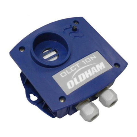
Oldham OLCT 10N User manual

Oldham
Oldham ctx 300 User manual

Oldham
Oldham OLC 100 User manual

Oldham
Oldham OLC 10 User manual

Oldham
Oldham OLC 100 User manual

Oldham
Oldham CTX 300 CO2 User manual

Oldham
Oldham OLC 10 User manual