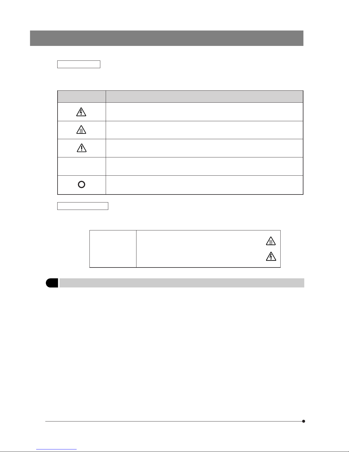
Olympus BX-URA2 User manual

INSTRUCTIONS
A X 7 6 2 5
BX-URA2
BX-RFA
U-LH100HGAPO
U-LH100HG
Power Supply Unit
U-25ND6-2
U-25ND25-2
U-25ND50-2
U-RSL6
U-RSL6EM
BX-RFSS
U-EXBABG
U-EXBAUB
U-EXBAUG
REFLECTED
FLUORESCENCE
SYSTEM
This instruction manual is for the Olympus Reflected Fluorescence System. To ensure the safety,
obtain optimum performance and to familiarize yourself fully with the use of this system, we recom-
mend that you study this manual thoroughly before operating the microscope. Retain this instruc-
tion manual in an easily accessible place near the work desk for future reference.
This publication is printed on 100% recycled paper


CONTENTS
IMPORTANT — Be sure to read this section for safe use of the equipment. — 1-3
Correct assembly and adjustments are critical for the reflected fluorescence system to exhibit its full performance. If you are
going to assemble the reflected fluorescence system yourself, please carefully read section 9, “ASSEMBLY” (pages 30 to 35).
I. REFLECTED FLUORESCENCE OBSERVATION
1 NOMENCLATURE
2
REFLECTED FLUORESCENCE OBSERVATION PROCEDURE
3 USING THE CONTROLS
4 SIMULTANEOUS FLUORESCENCE OBSERVATIONS
5 TROUBLESHOOTING GUIDE
6 SPECTRAL CHARACTERISTICS OF FILTERS
7 SPECIFICATIONS
4-5
6-7
8-15
16
17
18-22
23
1General Precautions for Observation....................................................................................................................... 8
2Selecting the Fluorescence Mirror Unit....................................................................................................... 8-10
3Objectives for Various Observation Modes........................................................................................ 10-11
4Turning the Power Supply Unit On............................................................................................................................. 11
5Centering the Field Iris Diaphragm.......................................................................................................................... 12
6Centering the Aperture Iris Diaphragm .............................................................................................................. 13
7Centering the Mercury Burner................................................................................................................................ 14-15
8Mounting the ND Filters ............................................................................................................................................................ 15
Simultaneous Reflected Fluorescence and Transmitted Light Nomarski
Differential Interference Contrast (DIC) Observations .................................................................. 16
1
Simultaneous Reflected Fluorescence and Phase Contrast Observations
.............. 16
2

9 ASSEMBLY
— See this section for the replacement of the light bulb. —
9-1 Assembly Diagram ............................................................................................................................................................................ 30
9-2 Detailed Assembly Procedures ............................................................................................................................. 31-35
30-35
II. REFLECTED OBSERVATIONS (BX-URA2 Only)
1 CONFIGURATION OF REFLECTED OBSERVATION SYSTEM
2 ASSEMBLY
3
FIELD IRIS AND APERTURE IRIS DIAPHRAGM ADJUSTMENTS
4 OBSERVATIONS
4-1 Reflected Light Brightfield/Darkfield Observations ........................................................................... 39
4-2
Reflected Light Nomarski Differential Interference Contrast (DIC) Observation
...... 40-42
4-3 Reflected Light Simple Polarized Light Observation....................................................................... 42
5
OPTICAL CHARACTERISTICS
«UIS2 (UIS) Series for Reflected Light Observation»
6 TROUBLESHOOTING GUIDE
■PROPER SELECTION OF THE POWER SUPPLY CORD ......................................................................... 46-47
36
37
37-38
39-42
43-44
45
8 OPTIONAL MODULES 24-29
16-Position Filter Slider U-RSL6........................................................................................................................... 24-25
26-Position Barrier Filter Slider U-RSL6EM .................................................................................................. 26
3Rectangle Field Stop BX-RFSS (for exclusive use with the BX-RFA).................... 27
4
Exciter Balancers U-EXBABG/EXBAUB/EXBAUG (for exclusive use with the BX-RFA) ......
28-29

1
IMPORTANT
SAFETY PRECAUTIONS
This system employs a UIS2/UIS (Universal Infinity System) optical design, and should be used only with
UIS2/UIS microscopes, eyepieces, objectives and condensers for the BX2 series. (Some of the modules
designed for the BX series and objectives/eyepieces for the UIS series are also usable. For details,
please consult Olympus or the catalogues.) Less than optimum performance may result if inappropriate
accessories are used.
The use of a universal reflected fluorescence illuminator has enabled the installation of necessary fluorescence mirror units.
By combining the microscopy techniques as shown below, this system can efficiently be used to find fluorescence emis-
sion in any area of cells:
1. Reflected fluorescence observation + Transmitted light phase contrast observation
2. Reflected fluorescence observation + Transmitted Nomarski Differential Interference Contrast (DIC) observation
3. Reflected fluorescence observation + Transmitted Light Observation
In addition, the following observations are also by installing a general reflected light observation unit (BX-URA2 only):
1. Reflected brightfield/darkfield observations
2. Reflected Nomarski DIC observation
3. Reflected simplified polarized light observation
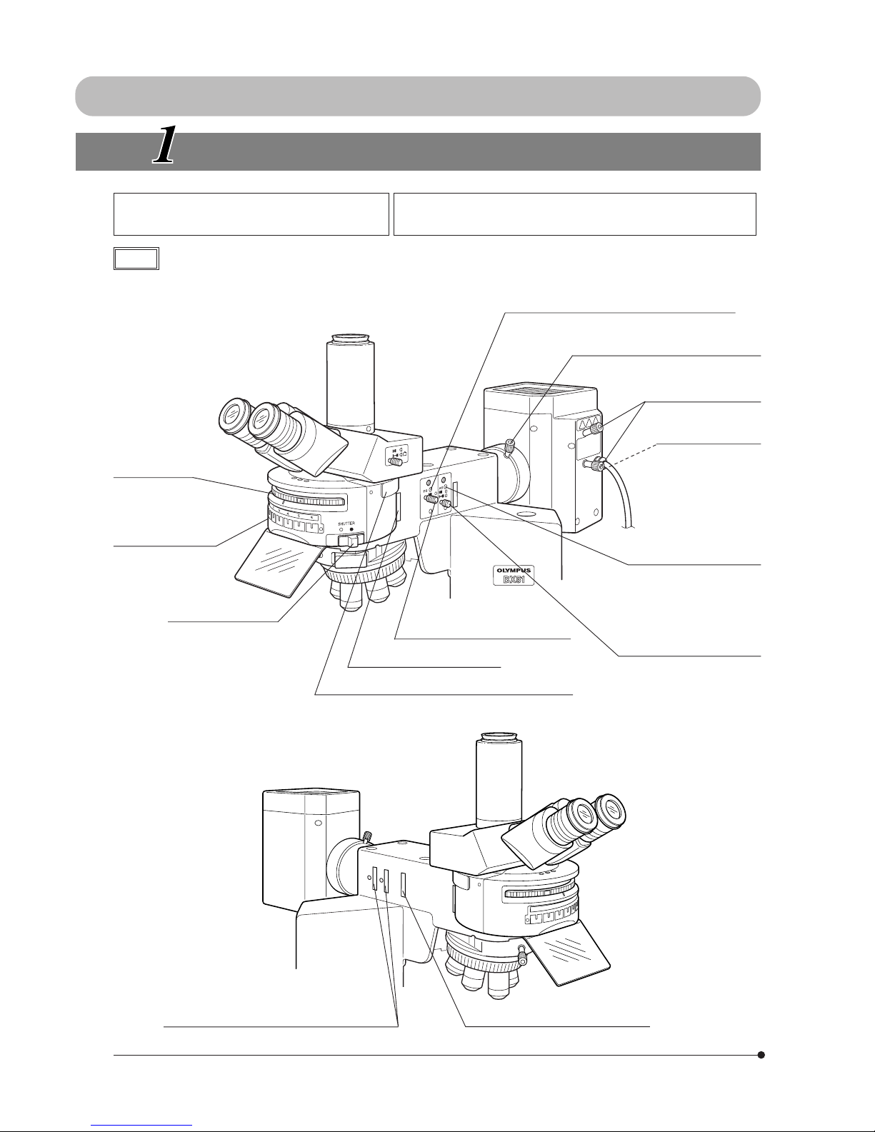
This manual describes the instructions for I. Reflected Fluorescence Observations in the first half and those for II. Reflected
Light Observations in the second half.
Please find the pages giving you the appropriate instructions for your observation.
1. This system is composed of precision instruments. Handle it with care and avoid subjecting it to sudden or severe
impact.
2. The ultrahigh-pressure mercury burner used should be the USH-103OL DC burner (mfd. by USHIO, Inc.) or the HBO103W/
2 burner (mfd. by OSRAM) that Olympus supplies.
3. Make sure that a mercury burner is attached and that cables are plugged in firmly.
4. The inside of the lamp housing is very hot and hazardous during lighting and for about 10 minutes after turning off. Do not
open the lamp housing in this period. (Page 11)
5. Do not apply excessive force to the stoppers which are provided for some functions. Otherwise, the stopper or equipment
may be damaged.
6. Do not attempt to open or disassemble the power supply unit because it includes high voltage parts inside.
7. Always use the power cord provided by Olympus. If no power cord is provided, please select the proper power cord by
referring to the section “PROPER SELECTION OF THE POWER SUPPLY CORD” at the end of this instruction manual. If the
proper power cord is not used, product safety and performance cannot be guaranteed.
Before plugging the power cord to the power outlet, make sure that the main switch of the power supply unit is set to
“ ” (OFF).
8. To ensure safety, be sure to ground the power supply unit. Otherwise, Olympus can no longer warrant the electrical safety
performance of the system.
9. Before opening the lamp housing for replacement of the burner or any other internal part, set the main switch to “ ”
(OFF), then unplug the lamp housing connection cable from the power supply unit, and wait for more than 10 minutes
until the lamp housing cools down.
The top panel of the lamp housing becomes very hot during operation. To prevent fire hazard, do not block the ventilation
through the top panel.
10
.

2
Symbol Explanation
l
Safety Symbols
The following symbols are found on the microscope. Study the meaning of the symbols and always use the equipment
in the safest possible manner.
Indicates the presence of high voltage (1 kV or more). Take caution to guard against electric
shock.
Indicates that the surface becomes hot, and should not be touched with bare hands.
Before use, carefully read the instruction manual. Improper use could result in personal injury to
the user and/or damage to the equipment.
Indicates that the main switch is ON.
Indicates that the main switch is OFF.
Warning indications
Warning indications are placed at parts where special precaution is required when handling and using the System.
Always heed the warnings.
Warning indication
position:
· Mercury burner lamp housing
(U-LH100HG, U-LH100HGAPO
· Power supply unit for 100 W
mercury burner
· ND filters
(U-25ND6, U-25ND25, U-25ND50)
[Warning against
high temperature]
[Warning against
high voltage]
1Getting Ready
1. This manual pertains only to the reflected fluorescence system. Before using this system together with the BX2 micro-
scope and associated options, make sure that you have carefully read and understood their manuals, and understand
how the system should be operated together.
2. The reflected fluorescence system is composed of precision instruments. Handle it with care and avoid subjecting it to
sudden or severe impact.
3. Do not use the system where it is subjected to direct sunlight, high temperature and humidity, dust or vibrations.
4. To allow heat from the unit to dissipate well, reserve a distance of at least 10 cm between the lamp housing and power
supply unit.
5. The power cord can also be used to cut the power supply in case of emergency. To make this possible, the power supply
unit should be installed so that the power cord connector (on the rear of the power supply unit) or the power outlet is
easily accessible for unplugging in case of emergency.

3
1. To clean the lenses and other glass components, simply blow dirty away using a commercially available blower and wipe
gently using a piece of cleaning paper (or clean gauze).
If a lens is stained with fingerprints or oil smudges, wipe it gauze slightly moistened with commercially available absolute
alcohol.
!Since the absolute alcohol is highly flammable, it must be handled carefully.
Be sure to keep it away from open flames or potential sources of electrical sparks --- for example, electrical
equipment that is being switched on or off.
Also remember to always use it only in a well-ventilated room.
2. With any part of the system other than glass components gets dirty, do not use organic solvents but wipe it with a clean
cloth. If the part is extremely dirty, use a lint-free, soft cloth slightly moistened with a diluted neutral detergent.
3. Do not disassemble any part of the system. This could result in malfunctions or reduced performance.
4. The mercury burner has a service life period of 300 hours (USH-103OL, HBO103W/2). When the hour counter on the
power supply unit indicates this value, set the main switch to “ ” (OFF) and wait for more than 10 minutes before
replacing the mercury burner (Page 33). Unlike electric bulbs, the mercury burner seals high-pressure gas inside. If it
continues to be used after the service life has expired, the glass tube may eventually explode due to accumulated
distortion.
5. When not using the microscope, be sure set the main switch to “ ” (OFF). After confirming that the lamp housing has
cooled down sufficiently, cover the microscope with the dust cover for storage.
6. When disposing of the microscope, check the regulations and rules of your local government and be sure to observe
them.
2Maintenance and Storage
The following symbols are used to set off text in this instruction manual.
!: Indicates that failure to follow the instructions in the warning could result in bodily harm to the
user and/or damage to equipment (including objects in the vicinity of the equipment).
# : Indicates that failure to follow the instructions could result in damage to equipment.
} : Indicates commentary (for ease of operation and maintenance).
3Caution
If the system is used in a manner not specified by this manual, the safety of the user may be imperiled. In addition, the
system equipment may also be damaged. Always use the system as outlined in this instruction manual.

4
I. REFLECTED FLUORESCENCE OBSERVATION
NOMENCLATURE
Reflected Illuminator BX-URA2
Fluorescence Illuminator BX-RFA
Note The diagram shows the BX-RFA. Parts
marked * are not provided on the BX-URA2.
100 W Mercury Apo Lamp Housing U-LH100HGAPO
100 W Mercury Lamp Housing U-LH100HG
Mirror unit turret
Mirror unit inscription
pocket (Page 31)
Shutter knob (Page 12)
\: Shutter OUT
{: Shutter IN Aperture iris diaphragm knob
(Page 13)
Collector lens focusing knob (Page 14)
Burner centering knobs
(Page 14)
Mirror focusing screw
(Page 15)
On the rear of the
lamp housing.
*6-Position filter slider inlet (Page 24)
Aperture iris diaphragm
centering screws (Page 13)
x2 screws.
Field iris diaphragm centering screws (Page 12)
x2 screws.
Field iris diaphragm knob (Page 12)
6-position filter inlet (Page 24)
Analyzer/6-position barrier filter slider inlet (Page 26)
ND filter/*exciter balancer inlet (Pages 15 & 28)
1
3
2
3
4
5
6

5
Fluorescence Mirror Units
U-MWU2, etc., total 24 models
Indicator sheets
}Up to six fluorescence mirror units can be mounted on the BX-RFA or BX-
URA2.
#Each filter unit includes a dichroic mirror, barrier filter and excitation
filter that have been combined according to the excitation method. It is
basically not recommended to open a fluorescence mirror unit.
}It is recommended that you use the U-MF2 dummy filter unit (which does
not contain a filter) when making your original fluorescence unit. (Page 32)
Blank indicator sheets provided with the illuminator can be used to write
the names of original fluorescence mirror units.
Power Supply Unit
(for 100 W mercury burner)
Burner ON LED
ND Filters
U-25ND6-2, U-25ND25-2, U-25ND50-2 Centering Target
U-CST
Hour counter
Main switch
Input
receptacle
Output
connector
I : ON
: OFF

6
(Controls Used) (Page)
Start observation.
(P. 11)
Set the main switch to “ I ” (ON) and wait for
the arc to stabilize.
REFLECTED FLUORESCENCE OBSERVATION PROCEDURE
}If you need simultaneous observation of reflected fluorescence observation with the phase contrast observation or trans-
mitted light Nomarski Differential Interference Contrast (DIC) observation, please read Chapter 4, “SIMULTANEOUS FLUO-
RESCENCE OBSERVATION”. (Page 16)
Preparation
· Attach the fluorescence mirror unit and objective matching the observation method. (Pages 8 to 11)
· Center the mercury burner. (Page 14 or 15)
@ Main switch
Place the specimen on the stage. ² Specimen holder
³ X-/Y-axis knobs
Engage the fluorescence mirror unit
matching the specimen in the light path. | Mirror unit turret
Engage the objective in the light path and
focus on the specimen. ƒ Revolving nosepiece
… Coarse/fine adjustment knobs
Engage an ND filter in the light
path as required.
Adjust so that the entire field is
uniform and brightest.
† ND filters
‡ Collector lens focusing knob
Adjust the field iris diaphragm. Š Field iris diaphragm knob
Adjust the aperture iris diaphragm. ‰ Aperture iris diaphragm knob
}Engage the shutter if you interrupt observation for a short time. ‹ Shutter knob
(P. 15)
(P. 14)
(P. 12)
(P. 13)
(P. 12)

7
} Make a photocopy of the observation procedure pages and post it near your microscope.
³
@
²
|
ƒ
…
†‡
Š
‰
‹

8
USING THE CONTROLS
1General Precautions for Observation
1. Verify that the power supply voltage and frequency match the requirements inscribed on the Rating plate.
2. Make sure that the power cord and connecting cables are plugged in securely.
3. If you perform only transmitted light phase contrast or transmitted light DIC observations, leave one cube position on the
turret empty. This allows for transmission of white light.
The turret must always be set to one of the click position. If it is deviated from a click position, the cover may be deformed
by heat.
4. Enlarge the field iris diaphragm so it just circumscribes the field of view. If decentered, center it using the Allen screwdriver.
5. Always use immersion for oil immersion objectives.
6. If you use an objective with correction collar such as the UPlanSApo40X, UPlanFLN60X, UPlanApo40X or PlanApo40X,
you can correct variations in cover glass thickness by adjusting the correction collar.
Correction procedure
If the cover glass thickness is known, match the correction collar to the cover glass thickness using the collar scale
provided. If the thickness is not known, turn the collection collar and adjust the fine adjustment knob to where the
image is as sharp as possible.
7. Engage the shutter if you interrupt observation for a short time.
(Turning the mercury burner ON and OFF repeatedly will significantly shorten the life span of the burner.)
8. Color fading of specimens
This system features high excitation light intensity to ensure bright observation of dark fluorescence specimens.
In consequence, after long period of observations using high-power objectives, the colors of specimens will fade quicker
than usual, causing the view (contrast) of fluorescent images to deteriorate.
In such a case, slightly reduce the excitation light intensity to slow color fading down and improve the fluorescence
images.
To reduce the excitation light intensity, use ND filters or aperture iris diaphragm as far as the observation is not affected or
use the shutter to limit the exposure of specimen to more than necessary light.
Commercially-marketed color fading protection agent (DABCO, etc.) can also delay fading of specimen colors. The use of
fading protection agent is recommended especially when you perform high-magnification observations frequently.
#Remember that the fading protection agents cannot be used with certain kinds of specimens.
Select the fluorescence mirror unit which matches the fluorochrome in use.
#Never mount or use the U-MBF3 brightfield mirror unit together with a with a mirror unit for fluorescence. The U-
MBF3 brightness is excessive and injury to the eyes could occur. If this type of mirror unit is to be used together
with a mirror unit for fluorescence, use the U-MBFL3 mirror unit equipped with a built-in ND filter or add a 3% ND
filter to the U-MBF3.
}Use according to the excitation wevelength:
Olympus has prepared some sets of fluorescence mirror unit combined with appropriate filters which are variable de-
pending on wavelengths.
The wide-band (W) set is normally used. There may be cases, however, where superwide-band (SW) or Narrow-band (N)
sets are recommendable.
2Selecting the Fluorescence Mirror Unit
@Extremely weak fluorescence brightness
(B- and G-excitation only):
Use the super-wide band (SW).
}With the SWB, strong autofluorescence may reduce
image contrast.
² Specimens emitting strong autofluorescence: Use the narrow band (N).
}The fluorescence bright is somewhat reduced.

9
Dichroic Mirror and Filter Configurations of Fluorescence Mirror Units
Excitation
Method Mirror Unit Dichroic Mirror Excitation Filter Barrier Filter Fluorochromes
· Autofluorescence observation
· DAPI: DNA staining
· Hoechest 33258, 33342: Chromosome
· Catecholamine
· Serotonin
· Tetracyline: Bones, teeth
· Quinacrine, quinacrine mustard:
Chromosome
· Thioflavine S: Lymphocyte
· Acriflavine: Nucleic acid
· ECFP
· FITC: Fluorescent antibody
· Acridine orange: DNA, RNA
· Auramine: Tubercle bacillus
· EGFP, S65T, RSGFP
· Rhodamine, TRITC: Florescent antibody
· Propidium iodide: DNA
· RFP
Texas Red: Fluorescent antibody
Color Separation Filter Combinations
For observing only the U-excitation stain,
when using U-excitation stain together
with FITC.
For observing only the B-excitation stain,
when using B-excitation stain with TRITC
or Texas Red.
Mirror Unit Name Meaning
For color separation
U- MN I B A 2
Excitation (U, V, BV, B, IB, G, IG or IY)
Bandwidth (SW: Superwide band. W: Wide band. N: Narrow band.)
Mirror unit
Universal
U
V
BV
B
IB
G
IG
IY
U U-MNUA2
IB U-MWIBA3
U-MNIBA3
DM400 BP360-370 BA420-460
DM505
BP460-495
BA510-550
BP470-495
U-MWU2
DM400 BP330-385 BA420
U-MNV2 DM455 BP400-410 BA455
U-MWBV2
DM455
BP400-440
BA475
U-MWB2
U-MNB2
U-MSWB2
DM500
BP460-490
BP470-490
BP420-480
BA520IF
U-MWIB3
U-MNIB3 DM505 BP460-495
BP470-495 BA510IF
U-MWG2
U-MNG2
U-MSWG2
DM570
BP510-550
BP530-550
BP480-550
BA590
U-MWIG3 DM570 BP530-550 BA575IF
U-MWIY2 DM600 BP545-580 BA610IF
U-MNU2 BP360-370
U-MNBV2 BP420-440
Model number (2 or 3)
For observing only the G-excitation stain,
when using G-excitation stain together
with Cy5.
GU-MWIGA3
U-MNIGA3 DM570 BP530-550 BA575-625
BP540-550

10
Excitation
Method Mirror Unit Dichroic Mirror Excitation Filter Barrier Filter Fluorochromes
3Objectives for Various Observation Modes
Exclusively for Fluorescent Proteins
Mirror Unit Name Meaning
U- MC F P HQ High Quality
CFP/GFP/YFP/RFP
Mirror unit
Universal
Objective Reflected light
fluorescence
Phase contrast
difference Transmitted light DIC
UPlanSApo 4X
10X 2
20X
20X O
40X 2
60X W
60X O
100X O
¦
¦
¦
¦
¦
¦
¦
¦
–
–
–
–
–
–
–
–
¦
¦
¦
¦
¦
¦
¦
¦
CFP U-MCFPHQ DM450HQ BP425-445HQ BA460-510HQ For ECFP
GFP U-MGFPHQ DM485HQ BP460-480HQ BA495-540HQ For EGFP
YFP U-MYFPHQ DM505HQ BP490-500HQ BA515-560HQ For EYFP
RFP U-MRFPHQ DM565HQ BP535-555HQ BA570-625HQ For RFP
UIS2 Series
–
¦
¦
¦
¦
–
¦
¦
¦
¦ : Recommended combination.
¦*: Slightly inferior in U-excitation.
–– : Not usable, or applicable objective is not available.
¦** : A phase contrast (Ph) objective is necessary for phase contrast observation.
PlanApoN 60X O
UPlanFLN 4X
10X 2
20X
40X
40X O
60X
60X OΙ
100X O2
100X OΙ2
–¦
–
¦**
¦**
¦**
–
–
¦**
¦**
–
¦
¦
¦
¦
¦
¦
¦
¦
¦
¦*

11
–
¦
¦
¦
¦
¦
¦
¦
¦
¦
¦
¦ : Recommended combination.
¦*: Usable, but image be dark depending on NA.
–– : Not usable, or applicable objective is not available.
¦** : A phase contrast (Ph) objective is necessary for phase contrast observation. The Ph objective is not
available for the UPlanFI100XOI3.
4Turning the Power Supply Unit On
Set the main switch to “ I” (ON). The arc will stabilize in 5 to 10 minutes after ignition.
}The discharge type mercury burner may not be ignited from the beginning on rare occasions due to its characteristics.
In this case, set the main switch to “ ” (OFF), wait for 5 to 10 seconds, then set it again to “ I” (ON).
#To extend the mercury burner life, do not turn the mercury burner off for 15 minutes after ignition.
#The mercury burner cannot be reignited until the mercury vapor has cooled down and liquefied. Before re-igniting
a mercury burner, wait for about 10 minutes after the last time it was turned off.
}For the shake of safety, the power supply to the lamp housing is shut down if the lamp housing is opened while the burner
is on. If this happens, set the main switch to “ ” (OFF), wait for more than 10 minutes, then set it again to “ I” (ON). Do not
open the lamp housing until it has cooled down enough.
#To reset the hour counter, hold its reset button till “000.0” is displayed.
Objective Reflected light fluorescence
U, V, BV B, IB, G, IY
Phase contrast
difference Transmitted
light DIC
UPlanApo 4X
10X
10X O
10X W
20X
20X O3
40X
40X O Ι3
60X
60X W3
100X O Ι3
PlanApo 40X
60X O3
100X O3
UPlanFI 4X
10X
20X
40X
60X O Ι3
100X O, OΙ3
UApo
20X 3/340
20X W3/340
40X 3/340
40X
OΙ 3/340
40X W3/340
¦
¦
¦
¦
¦
¦
¦
¦
¦
¦
¦
¦
¦
¦
¦
¦
¦
¦
¦
¦
¦
¦
–
¦**
–
–
¦**
–
–
¦**
–
–
¦**
–
¦
¦
–
¦
¦
¦
¦
–
¦
¦
–
¦
–
¦
¦
¦
–
¦**
–
–
¦
–
¦*
¦*
¦*
¦*
¦
¦
¦*
¦*
¦*
¦*
¦
¦
–
¦**
¦**
¦**
¦**
¦**
¦
¦
¦
¦
¦
¦
¦
¦
¦
¦
–
–
–
–
–
UIS Series

12
Fig. 1
5Centering the Field Iris Diaphragm (Fig. 1)
1. Close the light path by sliding the shutter knob @ to position marked {.
2. Engage the B or IB mirror unit in the light path by rotating the turret.
(If these mirror units are not available, engage another fluorescence mir-
ror unit in the light path.)
3. Open the light path by sliding the shutter knob to position marked \.
4 Engage the 10X objective in the light path, place the specimen on the
stage and bring the image into approximate focus.
5. Pull out the field iris diaphragm knob ² to minimize the field iris diameter.
6. Fit the Allen wrench provided with the microscope frame in the two field
iris centering screws ³ and adjust so that the iris image comes at the
center of the field of view.
7. While pushing in the field iris diaphragm knob ², enlarge the field iris
diaphragm until the field iris image inscribes the field of view. If eccentric-
ity is found after this, try centering again.
8. Enlarge the iris diaphragm until the iris image becomes almost the same
size as (i.e. circumscribes) the field of view.
Effects of Field Iris Diaphragm
The field iris diaphragm restricts the diameter of the beam of light enter-
ing the objective and thus excludes extraneous light, improving image
contrast. The field iris diaphragm also functions to prevent color fading of
fluorescent light in other part than the observed region.
To exclude extra light, set the field iris diaphragm knob ² on the fluores-
cence illuminator according to the objective power, so that the image of
the field iris diaphragm just circumscribes the field of view.
@
²
³

13
Fig. 2
6Centering the Aperture Iris Diaphragm (Fig. 2)
1. Close the light path by sliding the shutter knob @ to position marked {.
2. Engage the B or IB mirror unit in the light path by rotating the turret.
(If these mirror units are not available, engage another fluorescence mir-
ror unit in the light path.)
3. Engage the 10X objective in the light path and lace the U-CST centering
target on the stage.
4. Open the light path by sliding the shutter knob to position marked \.
5. Move the white surface with crosslines of the U-CST until the crosslines
are overlaid on the center of field.
6. Turn the revolving nosepiece to engage the empty place (the objective
cap should be removed) in the light path.
7. Pull out the aperture iris diaphragm knob ² to minimize the aperture iris
diameter.
8. Pull out the field iris diaphragm knob ³ to minimize the field iris dia-
phragm. Now the aperture iris image should be visible on the U-CST.
9. Fit the Allen wrench in the two aperture iris centering screws | and
adjust so that the aperture iris image coincides with the crosslines.
Effects of Aperture Iris Diaphragm
The aperture iris diagram helps adjust the brightness of the observed
image and improve the contrast.
To execute normal fluorescence observation, enlarge the aperture iris
diaphragm by pushing in the aperture iris diaphragm knob ².
}If specimen colors tend to fade due to too high excitation light, first use
ND filters to reduce the brightness, and decrease the aperture iris dia-
phragm if the ND filters are not enough.
Do not decrease the aperture iris diaphragm too much. Do not use it as
a substitute to the shutter.
@
²
³
|

14
Fig. 3
7Centering the Mercury Burner
}Set the main switch to “ I” (ON) and wait for 5 to 10 minutes until the arc
stabilizes before proceeding to the mercury burner centering.
1. Close the light path by sliding the shutter knob @ to position marked {.
2. Engage the B or IB mirror unit in the light path by rotating the turret.
(If these mirror units are not available, engage another fluorescence mir-
ror unit in the light path. Also note that, when using a U-excitation fluores-
cence mirror unit, be sure to observe the specimen through a UV cut
plate.)
3. Engage the 10X objective in the light path, place the U-CST centering
target on the stage, and adjust the centering of the center of crosslines
on white surface of the U-CST with respect to the center of field of view.
4. Turn the revolving nosepiece to engage the empty position (the objective
cap should be removed) in the light path.
5. Pull out the field iris diaphragm knob ² (to minimize it) and push in the
aperture iris diaphragm knob ³ (to enlarge it).
6. Open the shutter by setting shutter knob @ to position marked \.
7. Project the arc image on the U-CST by turning the collector lens focusing
knob |. (A)
If the arc image is not protected, adjust the burner centering knobs ƒ.
8. ring the arc image on the center of the left (or right) half of the field by
turning the burner centering knobs ƒ. (B)
9. Focus on the mirror arc image by adjusting the mirror focus screw … (Fig
4) on the rear of the lamp housing using the Allen screwdriver. (C)
Overlay the arc image with the mirror arc image by turning the burner
centering knobs ƒ. (D)
}During observation, adjust the collector lens focusing knob | so that the
observed field is uniform.
}Hereafter, the mercury burner centering need not be adjusted until the
next time the mercury burner is replaced.
@²³|
ƒ
A
B
C
D
10
.

15
Precise Centering of the Mirror Arc Image
Fig. 4
}The mirror arc image position has been adjusted and fixed at the factory.
Perform the centering of the mirror arc image after completing the center-
ing of the mercury burner and only when you want to make your adjust-
ments very strict and precise.
Note that, once this adjustment has been executed, the mirror can never
be returned to the same status as the factory shipment status.
1. Using a pair of tweezers, etc., peel off the two blind seals † from the rear
of the lamp housing.
2. Loosen the screws below the seals using the Allen screwdriver. The mir-
ror is unclamped when these two screws are loosened.
3. Then peel off another couple of blind seals ‡. This exposes the mirror
arc image centering holes.
4. Adjust the centering of the mirror arc image using the Allen screwdriver
in these holes.
Fig. 5
8Mounting the ND Filters
}Specimen color fading can be delayed by reducing the excitation light
intensity with ND filters. Use the ND filters as far as they do not hinder
observations.
· As necessary, up to two ND filters (with ND of 6 and 25) may be
individually inserted into filter insertion positions @ and/or ². Insert
the ND filters (U-25ND6-2 and/or U-25ND25-2, U-25ND50-2) with the
marked side facing toward the observer.
The ND filters must be inserted in the correct orientation. Otherwise, the
ND filters may be damaged.
· As you insert a filter, you will hear two clicks. At the first, the filter is at the
at an empty position, and at the second click the filter enters the light
path.
Note that the metallic filter frame will be very hot if you leave the filter
inserted for a long time while the mercury burner is on.
Do not leave the filter insertion positions in other positions than the
click positions for a long period of time.
@
²
…
†
‡

16
SIMULTANEOUS FLUORESCENCE OBSERVATIONS
}By properly combining equipment, this system can be used in transmitted light brightfield observation, transmitted phase
contrast observation and transmitted light DIC observation in addition to the reflected fluorescence observation. With
specimens that fade rapidly, fading can be minimized by initially using transmitted light phase contrast or transmitted light
DIC observation for positioning. Reflected fluorescence observation can also be executed simultaneously with phase
contrast or DIC observation, making it easy to tell which portion of the specimen is fluorescing.
1Simultaneous Reflected Fluorescence and Phase Contrast Observations
The phase contrast observation requires a phase contrast condenser (U-PCD2) or a universal condenser (U-UCD8) and
a Ph objective.
1. Engage a dummy mirror unit (or an empty position on the turret) in the light path.
2. Rotate the phase contrast turret to show the same number as the Ph number shown on the objective.
3. Adjust the optical axis between the ring sit and phase plate by centering them.
4. Engage the mirror unit corresponding to the desired excitation into the light path and open the shutter.
5. Adjust the transmitted light for the best balance of fluorescence and phase contrast brightness, and you are ready for
observation.
}Use ND filters or the light intensity control lever on the microscope base to adjust the transmitted light intensity.
}For details on using phase contrast observation, refer to the instruction manual provided with the phase contrast con-
denser or universal condenser.
Simultaneous Reflected Fluorescence and Transmitted Light Nomarski Differential
Interference Contrast (DIC) Observations
The transmitted light Nomarski DIC observation requires the following accessories; 1) universal condenser (U-UCD8); 2)
transmitted light DIC slider (U-DICT, U-DICTS, U-DICTHR or U-DICTHC); 2) analyzer (U-AN or U-AN360-3); 6- or 7-position
revolving nosepiece for DIC (U-D6RE or U-D7RE).
}In order for reflected fluorescence to be effective in the simultaneous observation, insert the analyzer (U-AN or U-AN360-
3) into the analyzer inlet slot above the dichroic mirror on the illuminator.
Do not insert the U-ANT analyzer in the transmitted light DIC slider, for this will dim the fluorescence observation image
and cause the analyzer to be burnt.
1. Engage the dummy mirror unit (or an empty position on the turret) in the light path.
2. Adjust the polarizer on the universal condenser to the “crossed Nicol” (complete extinction) status.
3. Insert the transmitted light DIC slider into the position provided on the nosepiece.
4. Rotate the turret on the universal condenser to select the Nomarski prism matching the objective to be used for observa-
tion.
5. Engage the objective to be used in the light path.
6. Place the specimen on the stage and focus on the specimen.
7. Adjust the field iris diaphragm of the transmitted light illumination unit (built into the microscope base) and the aperture iris
diaphragm of the universal condenser.
8. Turn the prism movement knob on the transmitted light DIC slider to adjust contrast of the DIC image.
9. Engage the mirror unit corresponding to the desired excitation in the light path and opent the shutter.
Adjust the transmitted light for optimum fluorescence and DIC image brightness.
}For details on the transmitted light DIC observation, refer to the instruction manual provided with the U-UCD8 transmitted
light universal condenser.
2
10.
Notes
}We recommend the use of the highly wear-resistant U-ANH analyzer-slider instead of the U-AN analyzer when you are
frequently switching between reflected fluorescence observation and transmitted light Nomarski DIC observation and
need to use both observations simultaneously.
}However, if you are frequency switching between reflected fluorescence observation and transmitted light Nomarski DIC
observation but you do not need to use both simultaneously, then it will be more convenient for you to use the M-DICT3
DIC mirror unit instead of an analyzer (U-AN or U-ANH). This facilitates the switching operation because the analyzer
simultaneously enters the light path when the fluorescence mirror unit is switched to the DIC mirror unit.
This manual suits for next models
12
Table of contents
Other Olympus Microscope manuals

Olympus
Olympus CK30 User manual

Olympus
Olympus SZ-III User manual

Olympus
Olympus CK2 User manual

Olympus
Olympus CX41 User manual

Olympus
Olympus POS User manual

Olympus
Olympus CHA-P User manual

Olympus
Olympus U-DA User manual

Olympus
Olympus IX73 User manual

Olympus
Olympus DP21-SAL User guide

Olympus
Olympus BH2 Series User manual

Olympus
Olympus BH2 Series Guide

Olympus
Olympus BX41 User manual

Olympus
Olympus DP71 User manual

Olympus
Olympus CKX41 Installation guide

Olympus
Olympus AL120-12 Series User manual

Olympus
Olympus BX53-P User manual

Olympus
Olympus VMF User manual

Olympus
Olympus VS110 Fluorescence User manual

Olympus
Olympus CHA-P User manual

Olympus
Olympus CX31 User manual