Olympus U-UVF248A User manual

MOTORIZED 248 nm UV
MICROSCOPE UNIT
INSTRUCTIONS
U-UVF248A
A X 7 6 8 0
This instruction manual is for the Olympus Motorized 248 nm UV Microscope Unit Model U-UVF248A.
To ensure the safety, obtain optimum performance and to familiarize yourself fully with the use of
this unit, we recommended that you study this manual thoroughly before operating the microscope
system. To understand the comprehensive operating procedures, it is also recommended to read
the instruction manual for the manual type U-UVF248 unit (packaged together with the U-UVF248IM).
Retain this instruction manual in an easily accessible place near the work desk for future reference.

In accordance with European Directive 2002/96/EC on Waste Electrical and Electronic Equipment,
this symbol indicates that the product must not be disposed of as unsorted municipal waste, but
should be collected separately.
Refer to your local Olympus distributor in EU for return and/or collection systems available in your
country.
NOTE: This equipment has been tested and found to comply with the limits for a Class A digital device,
pursuant to Part 15 of the FCC Rules. These limits are designed to provide reasonable protection
against harmful interference when the equipment is operated in a commercial environment. This
equipment generates, uses, and can radiate radio frequency energy and, if not installed and used in
accordance with the instruction manual, may cause harmful interference to radio communications.
Operation of this equipment in a residential area is likely to cause harmful interference in which case
the user will be required to correct the interference at his own expense.
FCC WARNING: Changes or modifications not expressly approved by the party responsible for compliance
could void the user's authority to operate the equipment.
For Korea only
A급 기기 (업무용 방송통신기자재)
이 기기는 업무용(A급) 전자파적합기기로서 판 매자 또는 사용자는 이 점을
주의하시기 바라 며, 가정외의 지역에서 사용하는 것을 목적으로 합니다.
This device complies with the requirements of directive 2004/108/EC concerning electromagnetic compatibil-
ity and of directive 2006/95/EC concerning electrical equipment designed for use within certain voltage limits.
CE marking means the conformity to these directives.
EN61326-1 defines two categories according to the location for use.
Class A: Equipment suitable for use in establishments other than domestic, and those directly connected to
a low voltage power supply network which supplies buildings used for domestic purposes.
Class B: Equipment for use in domestic establishments, and in establishments directly connected to a low
voltage power supply network which supplies buildings used for domestic purposes.
This device is applied Class A. Some interference may occur if this device is used in domestic location.

CONTENTS
IMPORTANT — Be sure to read this section for safe use of the equipment. — 1-3
1 NOMENCLATURE
2 CONTROLS
3 PREPARATION
4
SUMMARY OF VISIBLE/UV LIGHT OBSERVATION PROCEDURE
5 SPECIFICATIONS
6 TROUBLESHOOTING GUIDE FOR UV OBSERVATION
7 ASSEMBLY
4
5
6,7
8
9
10
11,12
U-UVF248A
1Centering the Mercury/Xenon Burner...................................................................................................................... 6
2Adjusting the Illumination Center ................................................................................................................................... 7
8
PREVENTIVE INSPECTION SHEET FOR ILLUMINATION DEVICES
13

1
IMPORTANT
With the U-UVF248A unit, the U-UVF248LB that is the manual type light source box is replaced with the
U-UVF248LBM that is the motorized type light source box. The U-UVF248LBM is capable of motorized
control of the opening/closing of the shutter and the adjustment of the light intensity.
The applicable scope is also changed to the MX61A motorized microscope frame, and additional mod-
ules and the MX2-BSW control software are newly necessary.
The present instruction manual pertains only to the information specific to the motorized operations. For
other information, please refer to the instruction manual for the manual type U-UVF248 unit (packaged
together with the U-UVF248IM).
Precautions on UV Light
1. The motorized shutter monitors the drive status of the MX61A to prevent accidental irradiation of UV light. However, care
is still required against UV leak from the revolving nosepiece and specimen surface.
2. To prevent unexpected irradiation of UV rays, be sure to close the idle objective positions of the revolving nosepiece by
attaching the caps provided with the revolving nosepiece.
3. Leakage of UV light can be prevented effectively by attaching the optional breath shield on the revolving nosepiece of the
MX61A.
4. Do not bend the UV light guide into a radius below 100 mm to prevent it from breaking. The UV light guide should be
inspected periodically to confirm absence of crack that may lead to UV leak.
UV caution labels
Contact Olympus for replacement in case a caution label is stained or peeled off or for other inquiries.
· Right side panel of the UV248 observation tube U-UVF248IM
· Right side panel of the UV248 light source box U-UVF248LBM

2
U-UVF248A
SAFETY PRECAUTIONS
Safety Symbols
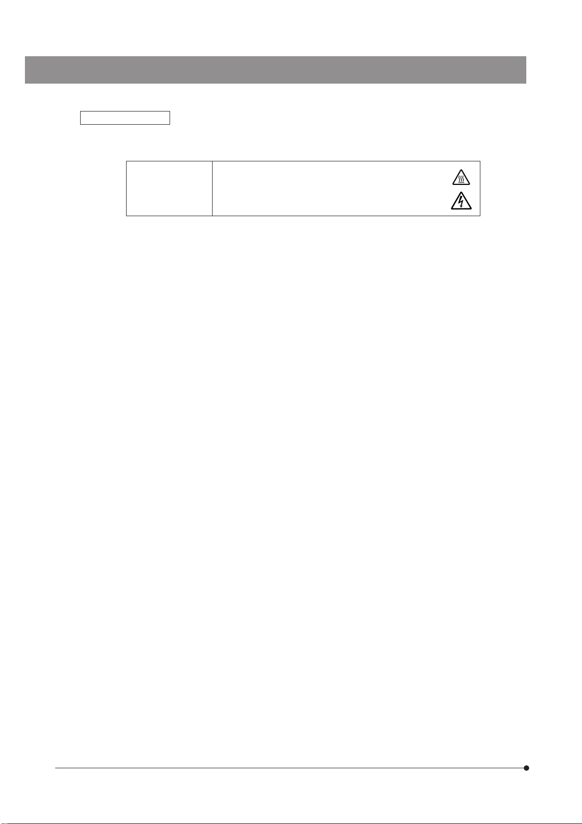
The following symbols are found on the unit. Study the meaning of the symbols and always use the equipment in the
safest possible manner.
l
Explanation
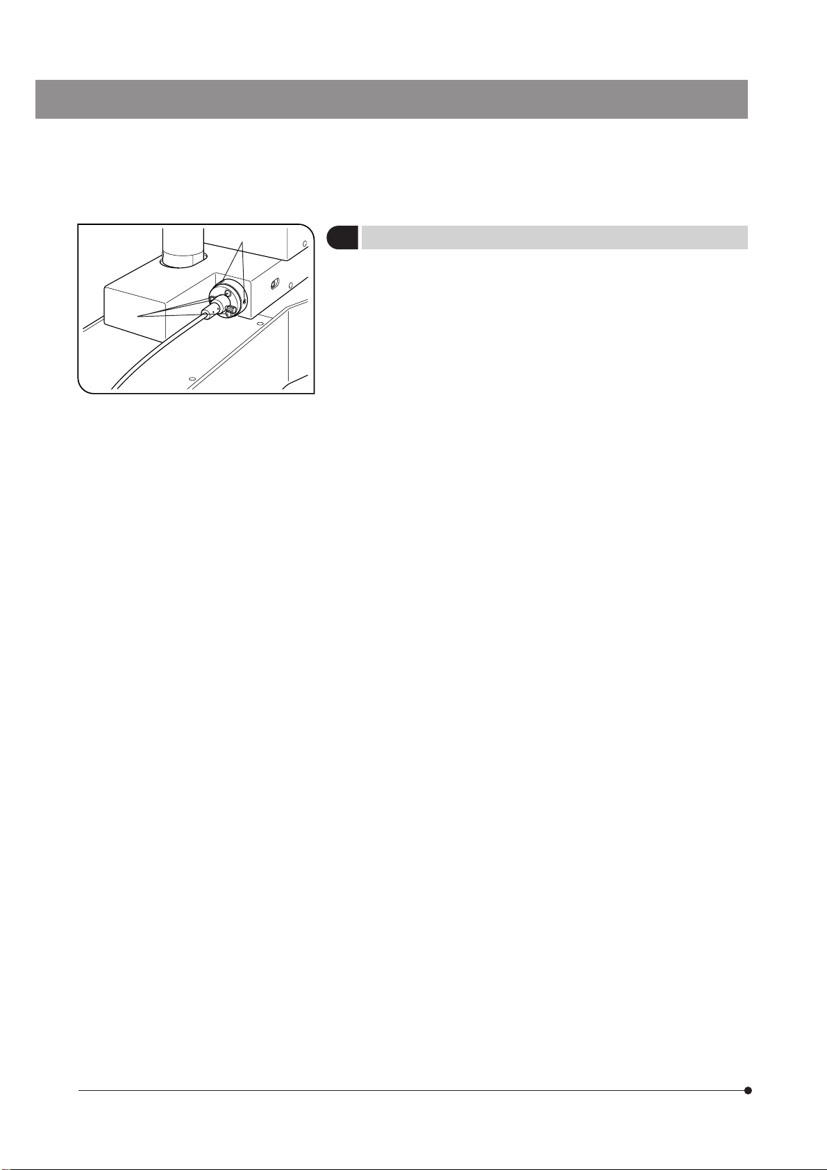
A high voltage (1 kV or more) is present. Be careful against electric shock.
Symbol
Indicates that the surface becomes hot, and should not be touched with bare hands.
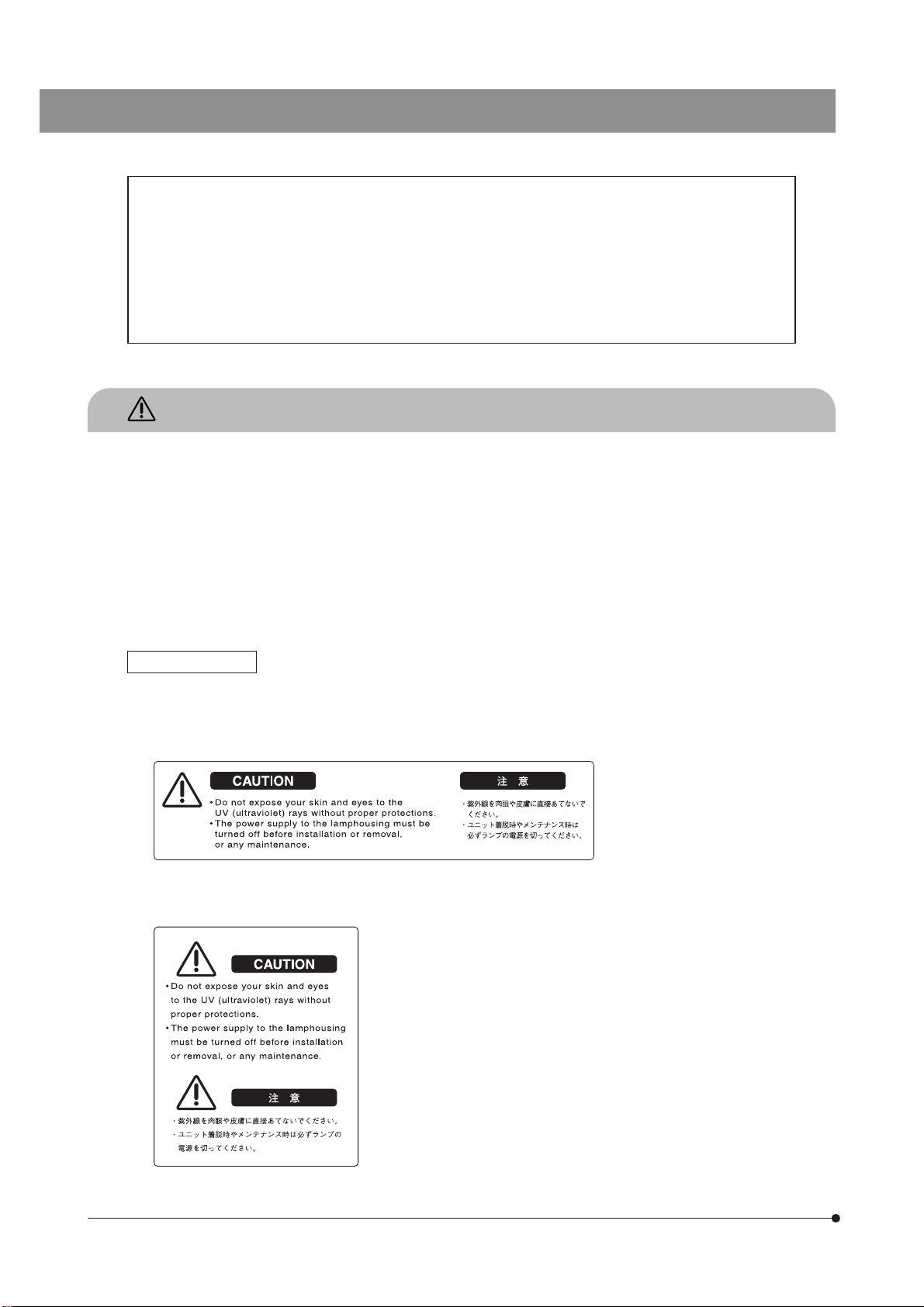
Before use, carefully read the instruction manual. Improper handling could result in injury to
the user and/or damage to the equipment.
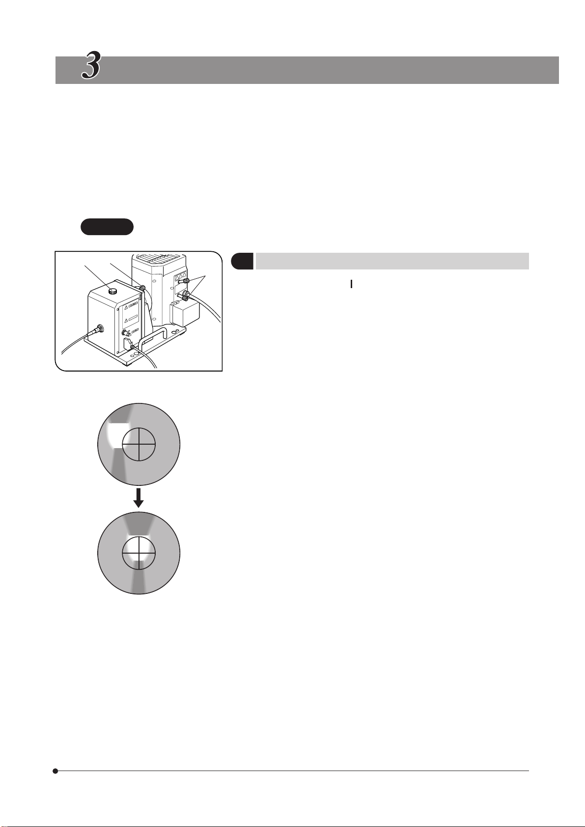
Indicates that the main switch is ON.
Indicates that the main switch is OFF.
1. This unit is a precision instrument. Handle it with care and avoid subjecting it to sudden or severe impacts.
2. The mercury/xenon burner should be the UXM80E (USHIO), which is available through Olympus.
3. Before using the unit, ensure that the burner is mounted and that cords are connected properly.
4. The lamp housing becomes very hot during and right after use. Do not open the lamp housing during these periods.
5. When the hour counter on the power supply indicates 1000 hours, set the main switch to “ ” (OFF), wait for more than
10 minutes and then replace the burner. Unlike a fluorescent lamp, the mercury/xenon burner seals high-pressure gas
inside. If it is used extremely beyond the service life, accumulated distortion of the glass tube could cause the burner to
burst, though this is a very rare case.
6. The power supply contains high-voltage parts inside and should not be disassembled.
7. Always use the power cord provided by Olympus. Before connecting the power cord into the power outlet, ensure that the
main switch of the power supply is set to “ ” (OFF).
8. Be sure to ground the power supply to ensure safety. If it is not grounded/earthed, Olympus can no longer warrant the
electrical safety performance of the equipment.
9. Before opening the lamp housing for replacing the burner, etc., be sure to set the main switch of the power supply to “ ”
(OFF), disconnect the lamp housing output connector on the power supply, and wait for more than 10 minutes after use
to cool down the burner.
10. The top panel of the lamp housing becomes very hot during operation. To prevent a fire hazard, be sure not to block
ventilation of this part. A space of 10 cm or more should also be reserved around the lamp housing to allow ventilation.
11. If a connection cable contacts the lamp housing or is distributed near it, the cable may melt and cause an electric shock.
To prevent this, be sure to distribute the connection cables at an enough distance from the lamp housing.
12. Do not apply an excessive force to any of the stopper mechanisms provided for the functions of the unit. Otherwise, the
stopper mechanism may be destroyed.
13. The power cord is used to shut down the power supply in case of emergency.
The power cord connector (on the rear of the power supply) or the power outlet should be easily accessible for power
cord disconnection in case of emergency.
14. Never insert a metallic object, etc. into a ventilation slot. Otherwise, an electric shock or malfunction may result.
15. To prevent the system from toppling down, do not combine the module if the total height of the microscope system
exceeds 1 meter.
16. The standard service life of the lamp housing is eight (8) years of use or 20,000 hours of total power ON period, whichever
is the shorter period.
For details, see Inspection Sheet on page 13.

3
Lamp housing for mercury/ High temperature caution]
xenon burner (U-LH80HGXE)
Power supply [High voltage caution]
Caution indications
Caution indications are affixed at parts where special precaution is required when handling and using the microscope.
Always heed the cautions.
Caution indication
positions

4
U-UVF248A
1
NOMENCLATURE
The modules enclosed in belong to the U-UVF248A UV Microscope Unit.
Other modules should be prepared by the user.
The modules marked in the illustration are for exclusive use in a motorized system.
}If you have not completed the assembly yet, see chapter 7, “ASSEMBLY” before proceeding to the following.
TV camera/monitor for UV observation
Recommended TV camera: Sony XCD-SX910UV
Image measuring software
analySIS FIVE
Active AF unit
UV Objective
MApo100X for
248 nm UV Rays
Objectives for visible light
UIS2 (UIS) series
Microscope frame
MX61A
UV248 Observation Tube
U-UVF248IM
UV Light Guide
U-UVF2FB/
U-UVF5FB
Lamp Housing for Mercury/
Xenon Burner
U-LH80HGXE
Mercury/
Xenon Burner
UXM80E
UV248 Light
Source Box
U-UVF248LBM
Power Supply
for Mercury/
Xenon Burner
U-HX-T
Computer
(With the MX2-BSW
control software)
Control Box
BX-UCB
(With the U-DICPCB
option board)

5
CONTROLS
UV248 Light Source Box
U-UVF248LBM
Centering scope (Page 6)
UV light guide mount
Camera cable connector
Caution label (Page 1)
Lamp housing mount (Page 12)
(BNC connector)
Motorized shutter/light intensity
adjustment cable connector
Motorized shutter/light intensity
adjustment cable

6
U-UVF248A
Fig. 1
PREPARATION
1Centering the Mercury/Xenon Burner (Figs. 1 & 2)
1. Set the main switch “ ” (ON). Between 5 to 10 minutes until the arc
image stabilizes.
2. Remove the cap @ of the centering scope by turning the cap counter-
clockwise.
3. Observing the UV-cut centering scope, adjust the following controls so
that the brightest and most well focused part of the arc image comes on
the center of the cross lines in the centering scope.
· Burner centering knobs ²
· Collector lens focusing knob ³
4. Set the DUV observation mode and perform the final adjustment to make
the image observed on the UV observation monitor brightest.
5. Attach the cap @ in the original position.
}After long hours of use, the electrodes will be consumed and the
centering position be deviated. The centering should therefore be
adjusted periodically.
Be sure to re-adjust centering after replacing the burner.
Fig. 2
}The motorized control of the MX61A and U-UVF248A is executed using the MX2-BSW control software.
For details on the software, refer to the instruction manual provided with it.
CAUTION To prevent accidental UV irradiation due to mistake, it is prohibited to control a system combining
the MX-OPU61A controller or the MX-HS61A with the MX61A.
@²
³

7
2Adjusting the Illumination Center (Fig. 3)
}This adjustment consists of aligning the UV light guide with the center of
the MApo100X objective for 248 nm UV observation.
1. Set the MX61A to the “BF” observation mode.
2. Place a specimen with a mirror surface on the stage.
3. Bring the specimen into focus by switching the objectives for visible light
from the lowest to the highest magnifications.
4. Switch the observation mode to the “DUV.”
The MApo100X objective for 248 nm UV light is automatically engaged
in the light path.
5. Set the shutter switch to “Open” to open the shutter.
6. Bring the specimen into focus by observing the monitor for UV observa-
tion. If the observation image is not displayed or abnormally dark, the
illumination center is deviated. In this case, the light guide mount should
be adjusted.
7. Using a Phillips screwdriver, loosen slightly the three clamping screws @
of the UV light guide mount.
8. Insert the provided Allen screwdriver alternatively into the two adjustment
screws ² and turn the screws until the brightest observation image is
obtained.
9. After completing the adjustment, be sure to tighten the three clamping
screws @.
}Hereafter, the illumination center adjustment is not required until the UV
light guide is replaced. However, when a combined microscope is
changed or an AF unit is added, the illumination center needs to be
readjusted.
The UV light guide is a consumable part. It should be replaced when the
image is deteriorated to a degree it cannot be rendered brighter even by
adjusting the illumination center.
Fig. 3
@
²

8
U-UVF248A
}The motorized control of the MX61A and U-UVF248A is executed using the MX2-BSW control software.
}The mercury/xenon burner takes 5 to 10 minutes until the arc is stabilized after ignition.
SUMMARY OF VISIBLE/UV LIGHT OBSERVATION PROCEDURE
Turn on the system.
Visible light observation
UV observation
(Operation)
1. Switch the power supply for the mercury/xenon burner to “ I” (ON).
2. Switch the computer ON.
3. Switch the BX-UCB control box ON.
4. Switch the UV TV camera and monitor ON.
5. Switch other setup modules ON.
1. Select the “BF” observation mode using the menu of the MX2-BSW.
2. Engage a visible-light objective with low magnification in the light path.
3. Place the specimen and adjust the focus and brightness.
4. Engage a visible-light objective with high magnification in the light path,
and adjust the focus and brightness. (Use autofocusing when the AF unit
is used.)
1. Select the “DUV” observation mode using the menu of the MX2-BSW
The MApo100X objective for UV light is automatically engaged in the
light path.
2. Set the shutter to “Open” using the menu of the MX2-BSW.
3. Adjust the focus and brightness of the monitored image using the menu
of the MX2-BSW.
Caution on UV light
Before maintenance or removal of a module, switch the power supply for the mercury/xenon burner and the control
box to “ ” (OFF) to avoid direct exposure of your eyes, skin or other body parts to the UV light.

9
SPECIFICATIONS
UV248 Light Source Box U-UVF248LBM
Item Specifications
Applicable light source Lamp housing: U-LH80HGXE.
Mercury/xenon burner: UXM80E (Life: Approx. 1000 hours).
Power supply: U-HX-T
Optical wavelength 248 ±4 nm.
Brightness adjustment 0% to 100%. Adjustment with pulse motor drive.
Shutter Shutter opening/closing with pulse motor drive.
Dimensions & weight 170(W) x 170(H) x 240(D) mm, approx. 3.6 kg.

10
U-UVF248A
TROUBLESHOOTING GUIDE FOR UV OBSERVATION
If problems occur, please review the following list and take remedial action as needed. If you cannot solve the problem
after checking the entire list, please contact Olympus for assistance.
Trouble Cause Remedy Page
The UV observation image on the
monitor is invisible or dark.
Cables are connected improperly or the
system is not turned on.
Check all connections and turn on
the system.
No mercury/xenon burner is mounted
on the lamp housing.
Mount the UXM80E mercury/xenon
burner.
The time elapsed after ignition of the
mercury/burner is short.
Wait for about 5 to 10 minutes until
the arc image stabilizes.
The shutter of the light source box is
closed.
Set the shutter to Open using the
menu of the MX2-BSW.
The observation mode other than “DUV”
is set.
Select “DUV” in the menu of the MX2-
BSW.
No UV-light objective is mounted on the
revolving nosepiece.
Mount the MApo100X objective for
248 nm UV light.
The mercury/xenon burner is not cen-
tered correctly.
Adjust the centering correctly.
The illumination center is deviated. Adjust it correctly.
The setting of the illumination lens ad-
justment screw is deviated.
Set it back to the factory-shipped set-
ting position (adjustment screw
rearmost stop position).
The UV light intensity is set too low. While observing the image, increase
the brightness using the menu of the
MX2-BSW.
The mercury/xenon burner is blown or
its life is expired.
Replace with the specified burner.
12
11
6
7
7
–
6
7
U-UVF248
6
8
11

11
Attaching the Mercury/Xenon Burner (Figs. 4 & 5)
1Attaching the UV248 Light Source Box (Figs. 4 to 6)
The burner and areas near it will be extremely hot during and right
after use. To prevent burns, wait until the burner and lamp housing
have cooled down after turning the burner off.
Do not touch the burner socket immediately after ignition. Other-
wise, an electric shock may result due to the remaining charge of
the high voltage required for ignition.
Before opening the lamp housing after use, set the power switch to
“ ” (OFF) and wait 10 minutes or more until the burner and lamp
housing have cooled down.
1. Loosen the socket clamping screw @ using the Allen screwdriver.
2. Hold the upper part of the lamp housing and pull it up straight to remove
the socket section.
# To prevent malfunction, do not hold the lamp housing by the center-
ing knobs ².
3. Place the socket section upside down as shown in Fig. 5.
}The lamp housing is equipped with the holder for transportation in the
factory shipment condition or with an old burner when the burner is
replaced. Remove the holder or old burner by loosening the two burner
holding screws ³.
4. Attach the burner so that the - (negative) pole comes at the top and
tighten the - (negative) pole side with one of the screws ³. Then fit the +
(positive) pole of the burner into the + (positive) side socket hole and
tighten the other screw ³.
Be sure to use the UXM80E burner (mfd. by USHIO) that is available
through Olympus.
#Be careful not to soil the burner with fingerprints or dust. If it
becomes dirty, wipe clean the burner surface with a piece of
gauze moistened with absolute alcohol.
# If contaminants are left on the burner surface, dark spots may appear
in the field of view during observation.
# The burner | should be attached so that projection ƒ on the tube is
oriented toward the burner mounting side and does not hinder the
light path.
#The trigger wire 6of the xenon burner should face the starter con-
necting surface so that it will not interfere with the light path.
Never disconnect the trigger wire 6as the burner will not ignite if
the wire is removed.
5. Attach the socket section with burner in the original position and tighten
the clamping screw @.
# To attach, align the external surface of the socket with that of the
lamp housing and push the socket straight downward.
Do not ignite the burner until the lamp housing is mounted on the
UV248 light source box. Otherwise, the UV rays may injure your eyes
or skin.
Fig. 4
@
²
Fig. 5
ASSEMBLY
# Some of the modules already mounted on the microscope system should be dismounted when mounting this
unit.
When dismounting or mounting a module, handle it carefully, remove dirt or dust on the mounting section and
take care not to damage the module.
³
|
…
ƒ

12
U-UVF248A
3Connecting Other Cables
1. Set the main switches of all of the modules equipped with main switches
to “ ” (OFF).
2. For safety, the connection of the power cord into the power outlet should
always be the last connected cable.
3. Be sure to connect each cable firmly.
Attaching the Lamp Housing (Fig. 6)
Do not bend the UV light guide into a radius below 100 mm to
prevent it from breaking. Also do not place a heavy object on the
light guide or subject it to strong force.
1. Remove the protective rubber caps from the two ends of the light guide.
Handle the light guide carefully so as not to leave stain or damage on
the end surfaces.
2. Insert the input connector @ into the UV light guide mount ² on the
UV248 light source box by aligning the positioning marks, and tighten
the clamping ring ³.
3. Loosen the clamping knob | and insert the output connector ƒ all
the way. Clamp the connection so that the clamping knob | is aligned
with the positioning reference plane ….
Fig. 6
1. Loosen the two lamp housing clamping screws @ of the UV248 light
source box.
2. Insert the mount seat ² of the lamp housing into the mount and tighten
the clamping screws @.
Attach the lamp housing and take care not to tilt it. Reserve enough
space around the lamp housing to ensure ventilation.
Resetting the Burner Hour Counter
Set the hour counter by referring to the instruction manual provided with
the power supply.
2Attaching the UV Light Guide (Figs. 7 & 8)
Fig. 7
Fig. 8
@²
@²
³
|
ƒ
…

13
PREVENTIVE INSPECTION SHEET FOR ILLUMINATION DEVICES
Check results (Date)
Check items ////
# If the spaces are not enough for check , copy this sheet.
1. More than 8 years have passed since original purchase or exceeds 20,000
hours of use.
2. Lamp does not light sometimes even through the power is on.
(Except discharge burners*1)
3. Light flickers when you move a lamp cable or illumination devices.
4. Lamp cable is unusually hot to the touch.
5. Burning or smoke odor.
6. Light still flickers after new lamp replacement.
(Except discharge burners*1)
7. Sings of deformation, backlash, or looseness, etc. when you assemble/
disassemble the illumination device.
(I.e. it is hard to open/ close the lid during lamp-replacement.)
8. Connection terminals or a lamp installation terminal have become discolored
or tarnished on the right or left side.
(Except discharge burners*1)
9. Illumination device/ housing has become deformed, cracked or tarnished in
any way.
10. Lamp cables or wiring parts have become deformed, cracked or tarnished in
any way.
{We recommend performing “Preventive Inspections” periodically (every time you replace lamps and at least once every 6
months).
{The table below identifies the check items to be observed. Put (X) if not applicable or ( ) if applicable.
{If there are any check marks ( ) noted, immediately stop use of the product and seek service or replacement for the
illumination device(s) for prevention.
{If you detect an abnormality other than that listed below with your illumination device or other Olympus product, request
inspection from your Olympus distributor.
If you have any questions, please contact your Olympus distributor.
11. Frequent repairs to similar devices put into use at the same time as the unit
being checked.
*1Discharge burners: Mercury burner / xenon burner / metal halide burner

MEMO

MEMO


Manufactured by
Distributed by
AX7680 03 Printed in Japan on December 25, 2012 M 000-03
Table of contents
Other Olympus Microscope manuals

Olympus
Olympus BH2-6RE User manual

Olympus
Olympus SZ61 User manual

Olympus
Olympus BX53 User manual

Olympus
Olympus MIC-D Operating instructions

Olympus
Olympus CX22LED User manual

Olympus
Olympus GX41 User manual

Olympus
Olympus CHBS User manual

Olympus
Olympus BH2 Series Operating instructions

Olympus
Olympus KHC User manual

Olympus
Olympus SZ4045TR User manual

Olympus
Olympus U-D7RES User manual

Olympus
Olympus CK40-TBI Operating instructions

Olympus
Olympus CKX41 Installation guide

Olympus
Olympus SZX10 User manual

Olympus
Olympus SZX16 User manual

Olympus
Olympus SZ-III User manual

Olympus
Olympus SZX10 User manual

Olympus
Olympus BX60M User manual

Olympus
Olympus BX3M-CB User manual

Olympus
Olympus BX51 User manual