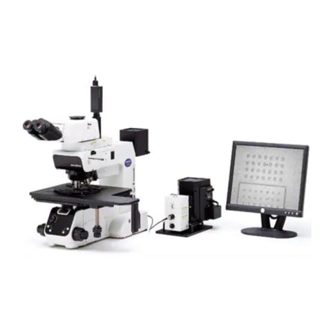
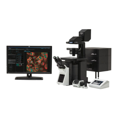
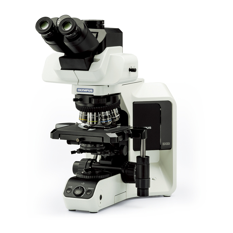
Olympus BX63 User manual

INSTRUCTIONS
BX63
INTELLIGENT MICROSCOPE
This instruction manual is for the Olympus Intelligent Microscope Model BX63.
To ensure the safety, obtain optimum performance and to familiarize yourself fully with the use
of this microscope, we recommend that you study this manual thoroughly before operating the
microscope.
Retain this instruction manual in an easily accessible place near the work desk for future reference.
A X 7 9 3 3

NOTE: This equipment has been tested and found to comply with the limits for a Class A digital device,
pursuant to Part 15 of the FCC Rules. These limits are designed to provide reasonable protection
against harmful interference when the equipment is operated in a commercial environment. This
equipment generates, uses, and can radiate radio frequency energy and, if not installed and used in
accordance with the instruction manual, may cause harmful interference to radio communications.
Operation of this equipment in a residential area is likely to cause harmful interference in which case
the user will be required to correct the interference at his own expense.
FCC WARNING: Changes or modifications not expressly approved by the party responsible for compliance
could void the user's authority to operate the equipment.
In accordance with European Directive 2002/96/EC on Waste Electrical and Electronic Equipment,
this symbol indicates that the product must not be disposed of as unsorted municipal waste, but
should be collected separately.
Refer to your local Olympus distributor in EU for return and/or collection systems available in your
country.
CALIFORNIA USA ONLY
The touch panel controller of this product uses a Lithium Battery which contains Perchlorate Material -
special handling may apply, See www.dtsc.ca.gov/hazardouswaste/perchlorate.

CONTENTS
Correct assembly and adjustments are critical for the microscope to exhibit its full performance. If you are going to assemble
the microscope yourself, please read section 9, “ASSEMBLY” (pages 39 to 44) carefully.
IMPORTANT -- Be sure to read this section for safe use of the equipment. -- 1-5
1 MODULE NOMENCLATURE 6
2 CONTROLS 7- 11
3 FLOW OF BRIGHTFIELD OBSERVATION 12,13
4 USING THE CONTROLS 14-32
4-2 Base............................................................................................................................................................................................................. 20,21
4-4 Stage (for the IX-SVL2)....................................................................................................................................................... 25,26
4-5 Observation Tube.................................................................................................................................................................... 27-29
4-6 Condenser.......................................................................................................................................................................................... 30,31
4-7 Immersion Objectives................................................................................................................................................................. 32
4-3 Stage (for the BX Series).............................................................................................................................................. 22-24
4-1 Touch Panel Controller.......................................................................................................................................................14-19
BX63
4-8 Objectives with Correction Collar.............................................................................................................................. 32
2Moving the Specimen
2Adjusting the Diopter
1Placing the Specimen
1Adjusting the Interpupillary Distance
1Centering the Condenser 2Compatibility of Objectives and
Condensers
1
Using the Filters
3Setting the Grounding
5Using the Light Shielding Sheet
3Using the Eye Shades 4Mounting the Eyepiece Micrometer
Disk
6Adjusting the Tilt
4Adjusting the X-Axis/Y-Axis Knob
Rotation Tension
5Selecting the Light Path of the
Trinocular Tube
2Using the Auxiliary Slide Holder
2Starting the System
1
Placing the Slide-Glass Specimen
1Basic Operations of Touch Panel
Controller
3Placing the 35 mm Dish Specimen
3System Setting
4Adjusting the X/Y-Axis Knob Rotation
Tension
4Selecting the Mode
1Using Immersion Objectives

5 CAMERA RECORDING 33
6 TROUBLESHOOTING GUIDE 34,35
7 SPECIFICATIONS 36,37
10 HALOGEN LAMP HOUSING INSPECTION SHEET 45
8 OPTICAL CHARACTERISTICS (UIS2 Series) 38
9 ASSEMBLY --
See this section for the replacement of the halogen light bulb.
-- 39-44
11 SET TYPE LIST 46-48
nPROPER SELECTION OF THE POWER SUPPLY CORD.......................................................... 49,50
2Selecting the Camera Adapter
Magnification
1System Chart
9-1 Assembly Diagram............................................................................................................................................................... 39-42
9-2 Detailed Assembly Procedures............................................................................................................................ 43,44

1
BX63
SAFETY PRECAUTIONS (Fig. 1)
1. If potentially infectious samples may be observed, use protective gloves or
other protective means to prevent the skin from contacting with samples
directly.
After observation, be sure to clean the portion contacted with samples.
· Moving this product is accompanied with the risk of dropping the
sample. Be sure to remove the sample before moving this product.
· In case the sample is damaged by erroneous operation, promptly take
the infection prevention measures.
· Follow the procedures described in Chapter “Getting Ready” (see
page 4) prior to using the accessories of this product. Otherwise, the
stability of the device will be lost and the dropped sample will cause
the possibility of infection.
· When you maintain the device which may have contacted with
potentially-infectious reagents, be sure to wear the protectors such as
gloves, or clean the device prior to operation.
· Before disposing of device contacted with potentially infectious samples,
be sure to follow the regulations and rules of your local government.
2 Be careful not to have your finger or hand caught by the space between
the revolving nosepiece arm @ and observation tube mount 2(Fig. 1).
3. Install the microscope on a sturdy, level table or bench.
4. Be careful not to tilt the microscope too much. Otherwise, the mobile
parts such as the light path selector knob may move.
5. Never insert metallic objects into the air vents of the microscope frame
as this could result in electrical shock, personal injury and equipment
damage.
6. Always use the power cord provided by Olympus. If no power cord is
provided, please select the proper power cord by referring to the section
“PROPER SELECTION OF THE POWER SUPPLY CORD” at the end of this
instruction manual. If the proper power cord is not used, product safety
performance cannot be warranted.
7. Always ensure that the grounding terminal of the microscope and that of
the wall outlet are properly connected. If the equipment is not grounded,
Olympus can no longer warrant the electrical safety performance of the
equipment.
This microscope employs a UIS2 (Universal Infinity System) optical design, and should be used only with
modules designed for the BX3-series and with UIS2 objectives/eyepieces.
For the applicable modules, please consult Olympus or the catalogues.) Less than optimum performance
may result if inappropriate accessories are used.
Configuration of Instruction Manuals
Since this microscope is expandable to a variety of systems, separate instruction manuals are prepared so
that the user has to read only the manuals according to the user’s own system.
Manual name Main contents
BX63 Transmitted light brightfield observation and touch panel
controller
BX3-CBH/U-MCZ Functions of the Control Box (incorporating power supply) and
the Controller
BX3-RFAA Motorized fluorescence illuminator
BX3-UCD8A Motorized universal condenser
BX3-SSU Scanning stage with ultrasonic
IMPORTANT
Fig. 1
1
2
2
Fig. 2
Operation Using the LED Lamp
Operation Using the Halogen Bulb
1. The surfaces of the lamp housing on the rear of the microscope will
become extremely hot during operation. When installing the microscope,
make sure to allow ample free space (10 cm or more) around and in
particular above the lamp housing for halogen bulb.
2. When installing the microscope, route the power cord away from the
lamp housing. Should the power cord come in contact with the hot lamp
housing, the power cord could melt and cause electric shock.
3. The standard service life of the lamp housing is eight (8) years of use or
20,000 hours of total power ON period, whichever is the shorter period.
For details, see Inspection Sheet on page 45.
4. To avoid potential shock hazards and burns when replacing the halogen
bulb, set the main switch 3to “ ” (OFF) and allow the lamp housing
| and bulb to cool before touching them (Fig. 2).
Designated halogen bulb 12V100WHAL-L (PHILIPS 7724)
Safety note on LED (Light Emitting Diode)
The LED incorporated in the LED lamp housing is a class 1 LED
product. The light emitted by LED is basically safe, but do not look at
the illumination light directly for an extended period to prevent your eye
from being injured
CLASS 1 LED PRODUCT
4
3

3
BX63
Safety Symbols
The following symbols are found on the microscope. Study the meaning of the symbols and always use the equipment
in the safest possible manner.
Symbol Explanation
Indicates that the surface becomes hot, and should not be touched with bare hands.
Indicates a non-specific general hazard. Follow the description given after this symbol or in
instruction manual.
Indicates that care is required against your finger or hand being caught.
Indicates that the main switch is ON.
Indicates that the main switch is OFF.
Caution indications
Caution labels are placed at parts where special precaution is required when handling and using the microscope. Always
heed the cautions.
Caution label
positions
Lamp housing
[Caution against high temperature]
Revolving nosepiece arm
[Caution against finger or hand being caught]
If a caution label is dirty or peeled off, contact Olympus for the replacement or other inquiry.

4
1 Getting Ready (Fig. 3)
Fig. 3
1. A microscope is a precision instrument. Handle it with care and avoid
subjecting it to sudden or severe impact. Also note that the microscope
does not have a waterproof construction.
2. Do not use the microscope where it is subjected to direct sunlight, high
temperature and humidity, dust or vibrations. (For the operating conditions,
refer to section 7, “SPECIFICATIONS”.)
3. When moving the microscope, carry it by holding the grasping part on the
rear of the arm and the front part of the base as shown in Fig. 3 (Weight:
Approx. 19 kg).
· Do not hold the rear cover plate because it is fragile.
· Before carrying, be sure to remove the dummy cover on the front
of the base as well as the specimen, eyepieces and filters so
that they will not drop during movement.
Also remove the modules from the microscope frame to reduce
the risk of heavy burden (Frame weight: Approx. 12 kg)
· To prevent damage to the microscope, never hold it by the stage,
stage fixing pillar or binocular tube, etc.
4. When the accessories of this product such as an intermediate attachment
are used, make sure that the system height does not exceed 1 meter (to
prevent the system from tipping over).
5. When the microscope needs to be packaged for forwarding to a
remote location, contact Olympus (to obtain advice for guaranteeing the
performance).
CAUTION
2 Maintenance and Storage
1. To clean the lenses and other glass components, simply blow dirt away using a commercially available blower and wipe
gently using a piece of cleaning paper (or with clean gauze).
If a lens is stained with fingerprints or oil smudges, wipe it gauze slightly moistened with commercially available absolute
alcohol.
Since the absolute alcohol is highly flammable, it must be handled carefully.
Be sure to keep it away from open flames or potential sources of electrical sparks --- for example, electrical
equipment that is being switched on or off, which could cause ignition of a fire.
Also remember to always use absolute alcohol only in a well-ventilated room.
2. Do not use organic solvents to clean the microscope components other than the glass components. To clean them, use
a lint-free, soft cloth slightly moistened with a diluted neutral detergent.
3. Do not disassemble any part of the microscope except for the parts that are specified to be disassembled in this manual,
as this could result in malfunction or reduced performance.
4. After using the microscope, set the main switch to “ ” (OFF), wait for the lamp housing to cool down sufficiently, and
keep it covered with a dust cover during storage.
5. Before disposing of this product, be sure to follow the regulations and rules of your local government.
CAUTION

5
BX63
This product complies with the requirements of directive 98/79/EC concerning in vitro diagnostic
medical devices. CE marking means the conformity to the directive.
4 Caution
If the microscope is used in a manner not specified by this manual, the safety of the user may be imperiled. In addition,
the equipment may also be damaged. Always use the equipment as outlined in this instruction manual.
The following symbols are used to set off text in this instruction manual.
: Indicates a potentially hazardous situation which, if not avoided, may result in minor
or moderate injury or damage to the equipment or other property. It may also be used
to alert against unsafe practices.
} : Indicates commentary (for ease of operation and maintenance).
CAUTION
3 Intended use
This product has been designed to be used to observe magnified images of specimens in various routine work and
research applications.
Do not use this product for any purpose other than its intended use.
This product is considered a medical device in the following country: US.
Safety and EMC Precautions
· This product complies with the emission and immunity requirements described in IEC61326 series.
· The electromagnetic environment should be evaluated prior to operation of this product. Do not use this product in
close proximity to the sources of strong electromagnetic radiation to prevent interference with the proper operation.
· Use only power cord which OLYMPUS specifies. Otherwise the safety and EMC perfomance of the product can not
be assured.
· Be sure to ground the product. Otherwise our intended electric safety and EMC perfomance of the product can not
be assured.
Use in domestic area
EN61326-1 defines two categories according to the location for use.
Class A: Equipment suitable for use in establishments other than domestic, and those directly connected to a low voltage
power supply network which supplies buildings used for domestic purposes.
Class B: Equipment for use in domestic establishments, and in establishments directly connected to a low voltage power
supply network which supplies buildings used for domestic purposes.
This product is applied Class A. Some interference may occur if this system is used in domestic location.

6
1MODULE NOMENCLATURE
}The modules mentioned below show only the typical product names. As there are some products that are not mentioned
but also applicable to this microscope, check the latest catalogues or consult Olympus.
The control of motorized modules is possible from the touch panel controller, the U-MCZ controller or a PC (commercially
available).
For the modules marked “*”, also read their instruction manuals.
Observation tube
· U-BI30-2
· U-TBI3-CLI
· U-TR30-2
· U-TTR-2
Eyepieces
· WHN10X
· WHN10X-H
Motorized 7 position
nosepiece/Coded 7
position nosepiece
· U-D7REA
· U-D7RES
Stage
· BX3-SSU*
·
BX3-STAD + Stage for BX
· IX-SVL2
Motorized fluorescence illuminator/Coded
fluorescence illuminator/Standard arm
· BX3-RFAA*
· BX3-RFAS*
· BX3-ARM
Microscope frame
BX63F
Controller
U-MCZ*
XY controller*
Lamp housing
· U-LHLEDC
· U-LH100ADP + U-LH100
Control box
(for BX3-SSU)
Touch panel controller
(Provided with the BX63F)
Condenser
· BX3-UCD8A*
· U-SC3
· U-AAC
Control box
BX3-CBH*

7
BX63
2CONTROLS
}If you have not yet assembled the microscope, read chapter 9, “ASSEMBLY” (pages 39 to 44).
Transmitted light observation combination
Interpupillary distance
adjustment scale (Page 27)
Diopter adjustment ring
(Page 27)
Slide holder (Page 22)
Dummy cover
Filter mount (Page 20)
Display panel
(See next page for details.)
Allen screwdriver
holder
Y-axis knob (Page 24)
X-axis knob (Page 24)
Light path selector knob (Page 28)

8
Display panel
ECO mode indicator
Brightness meter
Shutter indicators
OPEN/CLOSE
Observation mode indicators
FL/PH/DIC/BF/PO/DF
Mirror unit indicators
1 to 8
Control Box
BX3-CBH
*For details, read the separate instruction manual for “BX3-CBH/U-MCZ”.
The manual shows the wiring diagrams for the connection cables.
DIP switch
For use in operation setting.
Main switch
I : ON. : OFF.
Indicator LEDs
POWER: Power status indicator.
STANDBY: Standby mode indicator.
REMOTE: Remote control indicator.
ERROR: Error indicator
(which flashes in case of an error)
Cooling fan outlet
Do not block this outlet!!
(Keep a clearance of at
least 10 cm.)

9
BX63
Reflected light observation combination *For details, read the separate instruction manuals for the
BX3-RFAA and U-AW.
Motorized Fluorescence Illuminator
*
BX3-RFAA
Lamp Housing for 100W Mercury Burner
U-LH100HG
U-LH100HGAPO
Lamp Housing for 75W Xenon Burner
U-LH75XEAPO
Motorized
Attenuator
Wheel*
U-AW
Extension Adapter
for Lamp Housing*
U-LHEAD

10
Touch panel controller (provided with the BX63F)
Example of touch panel guidance screen
OFF button
Setting button
Help button
MENU button
Control panel
(Variable depending on
observation mode.)
Screen
Objective buttons
Observation mode buttons
Focus control panel
Controller
U-MCZ *For details, read the separate instruction manual for “BX3-CBH/U-MCZ”.
Coarse adjustment knob
Fine adjustment knob
Fluorescence brightness
control buttons st
SNAP (still image capture) button
LIVE/PAUSE button
Observation mode selector buttons
· PH: Phase contrast observation
· FL: Fluorescence observation
· DIC: Differential interference contrast observation
· BF: Brightfield observation
SHUTTER button
Transmitted light brightness control buttons st
Touch panel
Main switch
ON: Short push
OFF: Continuous push
DC input connector
24 V, 2.8 A
Signal cable

11
BX63
Stage Adapter
BX3-STAD
}This adapter is required when using the U-SVLB-4, U-SVRB-4, U-SVLO or U-SVRO stage for the BX series.
35 mm dish holder
Cross Stage
IX-SVL2
When installing this stage on the BX63, position it so that the stage knobs are on
the right.
Note that the BX3-UCD8A motorized universal condenser cannot be used when
this stage is installed.
CAUTION
Stage center plate
Y-axis knob
X-axis knob
IX-SCL stage clip mounting screw holes
}Use two holes on the front side.
(Do not use the holes on the rear side to
avoid interference with the objectives.)
Mounting dovetail

12
FLOW OF BRIGHTFIELD OBSERVATION
3
Adjust the interpupillary distance.
Adjust the diopter.
Adjust the light axis.
Adjust the brightness.
}This chapter describes the BF (brightfield observation) procedure of the Guidance mode. (Individual operations are
explained assuming the use of the touch panel controller provided with the BX63.)
}The Guidance mode button is defeated unless System Setting has been completed in the [MENU display] at the
system startup.
(Controls Used) (Page)
@
Main switch of BX3-CBH
(P. 8)
2
Main switch of touch panel controller
(P. 8)
3
Main switch of Control box (for BX3-SSU)
(P. 15)
4Guidance button (P. 19)
5BF button (P. 19)
6Light path selector knob (P. 28)
7Slide holder (P. 22)
8XY-Stage button (P. 19)
9Objective button (10X) (P. 19)
aBrightness tab (P. 19)
bFocus buttons/sliders (P. 19)
cBinocular tube (P. 27)
dDiopter adjustment ring (P. 27)
eCondenser height adjustment knob (P. 30)
fCondenser centering screws (P. 30)
In the Guidance mode, these are set au-
tomatically according to the objective.
9Objective button (any button) (P. 19)
bFocus buttons/sliders (P. 19)
aBrightness tab (P. 19)
Start observation.
Set the main switches to “ I ” (ON).
Press the Guidance button in the [MENU]
display.
Press the BF button in the preparations for
observation display.
Select the light path (in case of a trinocular
tube).
Place the specimen on the stage.
In the Guidance mode display, engage the
10X objective in the light path and adjust the
brightness.
Bring the specimen in focus.
Adjust the aperture iris and field iris diaphrag-
ms.
Engage the desired objective in the light path
and bring the sample in focus.

13
BX63
c
d
e
f
2
1
7
3
6
}Copy the observation procedure pages on separate sheets and post it near your microscope.
Motorized fluorescence illuminator
BX3-RFAA
Motorized attenuator wheel
U-AW
Motorized 7 position nosepiece
U-D7REA
Control box
(for BX3-SSU)
Control box
BX3-CBH
Touch panel controller
Motorized universal
condenser
BX3-UCD8A
Controller
U-MCZ
XY controller
a
b
9
8
{Guidance mode display
5
4
{MENU display {Preparations for observation

14
USING THE CONTROLS
4
4-1 Touch Panel Controller
1
Basic Operations of Touch Panel Controller
(Fig. 4)
1. The touch panel controller can be operated by directly touching the
displayed button with your fingertip.
The touch panel controller uses a static capacitance type touch
panel and may not react if it is touched by a finger wearing a
rubber or vinyl glove. So use a touch pen for a static capacitance
type touch panel.
2. The selected button turns blue to indicate that it is selected.
3. For the differences in the touch methods (tap, double-tap, drag and hold),
refer to the Help .
· When activating the touch panel controller, first turn the BX3-CBH control box ON and then turn the touch
panel controller ON.
· The touch panel controller controls the camera recording but cannot view or save the recorded images.
CAUTION
CAUTION
Fig. 4

15
BX63
CAUTION
2Starting the System (Fig. 5)
1. Set the main switch of the BX3-CBH control box to “ I” (ON).
2. Set the main switch on the rear panel of the touch panel controller to
ON.
3. If you are using the supersonic stage, set the main switch of its control
box to “ I” (ON).
4. The black startup display is displayed (for about 20 seconds), and then
the blue startup display appears.
When the initialization completes, the [Mode selection display] appears.
}When the main switches of the BX3-CBH and touch panel controller are
already ON and the touch panel controller is in the standby mode, the
display starts with the blue display.
5. Touch the Help button @ with your fingertip.
First read the following descriptions to understand how to operate the
touch panel controller.
· Basic operations of touch panel controller
· How to read the Help
· Guidance mode and Full Operation mode
The Function Description is to be referenced as required after starting
the actual operation.
When the touch panel controller is used for the first time,
Guidance and Full Operation cannot be selected unless
System Setting 2has been completed.
}The controller in the standby mode starts with
this display.
Fig. 5
2
1

16
Fig. 6
Fig. 7
1
2
3System Setting (Figs. 6 to 14)
The system setup is required when using the system for the first time or
after replacing a unit connected to the microscope.
The microscope cannot be controlled unless the unit setting
and optical setting are completed. Be sure to set them.
1. On the [MENU] display, drag the [USER] dial 1up or down to select one
of 1 to 31 or “GUEST.”
1 to 31: The microscope status at power OFF will be saved under
the selected number so that it can be reproduced when the
microscope is started up later.
GUEST: The microscope status is not saved and the microscope is started
up in the initial status next time it is started.
2. Tap the System Setting button 2. The [System Setting] display appears
on the touch panel screen (Fig. 7).
Unit Setting
This tab is used to set the units connected to the BX63.
1. Tap the [Unit] tab 1in the [System Setting] display to open the [Unit]
display (Fig. 8).
2. Set the units connected to the BX63. When the marking ² for the
desired module is tapped, the unit names are displayed. Select the units
used in the module and tap them.
}When the Unit Check button ³ is tapped, the information on the units
connected to the BX63 is acquired automatically and set. However, the
unit information on the lamp bulb and manual unit is not acquired.
}When the marking | in [Set Type] is tapped, the set numbers are
displayed. Select a set number and tap it to set the units according to
the contents of the selected set. For the set contents, see page 46.
3. Tap the OK button ƒ to save the setting. If you want to set another item,
tap the tab for the desired setting. If you want to exit the system setting,
tap the [X] marking to close the [System Setting] screen.
CAUTION
Fig. 8
2
5
4
3
1
Table of contents
Other Olympus Microscope manuals

Olympus
Olympus U-UVF248 User manual

Olympus
Olympus POS User manual

Olympus
Olympus BX61WI User manual

Olympus
Olympus BX-RFAA User manual

Olympus
Olympus CX41 User manual

Olympus
Olympus CH30 User manual

Olympus
Olympus U-CBE User manual

Olympus
Olympus STM7 User manual

Olympus
Olympus CK40-TBI Operating instructions

Olympus
Olympus BX51 User manual

Olympus
Olympus IX81 User manual

Olympus
Olympus U-DA User manual

Olympus
Olympus IX71 User manual

Olympus
Olympus CX22LED User manual

Olympus
Olympus 1X71 User manual

Olympus
Olympus CH Series Operating instructions

Olympus
Olympus IX71 User manual

Olympus
Olympus CHBS User manual

Olympus
Olympus BH2-6RE User manual

Olympus
Olympus SZ4045TR User manual