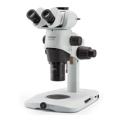
Olympus SZX16 User manual

INSTRUCTIONS
SZX16 REFLECTED
FLUORESCENCE SYSTEM
This instruction manual is for the Olympus SZX2 Reflected Fluorescence System. To ensure safety, obtain
optimum performance, familiarize yourself fully with the use of this equipment, we recommend that you
study this manual thoroughly before operating the microscope.
Retain this instruction manual in an easily accessible place near the work desk for future reference.
A X 7 4 7 6
Main modules described in this manual
SZX2-RFA16
Fluorescence filter units
SZX2-CCV
U-LH100HG
U-RFL-T

Compliance
This device complies with the requirements of both directive 2004/108/EC concerning electromagnetic
compatibility and directive 2006/95/EC concerning low voltage. The CE marking indicates compliance with
the above directives.

SZX16 REFLECTED FLUORESCENCE SYSTEM
CONTENTS
Correct assembly and adjustments are indispensable for the microscope to manifest its full performance. If you want to
assemble the microscope by yourself, see Chapter 5, “ASSEMBLY” (pages 8 to 12) first.
IMPORTANT — Be sure to read this section for safe use of the equipment. —
1 NOMENCLATURE
2 CONTROLS
3 OBSERVATION
1Fluorescence Observation ............................................................................................................................................................................... 5
2Transmitted Light Observation .................................................................................................................................................................... 5
1,2
3
4
5
5 ASSEMBLY
6 ADJUSTMENTS, GENERAL
1Centering the Mercury Burner.................................................................................................................................................... 13-15
2Mounting an ND Filter ....................................................................................................................................................................................... 15
3Using the Dummy Filters ............................................................................................................................................................................... 16
4Using the Exciter Balancer ................................................................................................................................................................. 17,18
8-12
13-18
PROPER SELECTION OF THE POWER SUPPLY CORD ................................................................... 19,20
4 SPECIFICATIONS 6,7
1Reflected Light Fluorescence Illuminator SZX2-RFA16 ......................................................................................... 6
2Combinations and Applications of Fluorescence Filters
Spectral Characteristics of Filters ............................................................................................................................................. 6,7
21
7 LAMP HOUSING INSPECTION SHEET

1
10. Before transporting the system, remove the modules attached to it to make the overall weight as lightweight as possible.
11. The standard service life of the lamp housing is eight (8) years of use or 20,000 hours of total power ON period, whichever
is the shorter period.
For details, see Inspection Sheet on page 21.
IMPORTANT
This equipment can provide the highest level of brightness required in macro fluorescence observation
using fluorescence filter units (up to 5 units can be mounted) when it is combined with the SZX2-ZB16 zoom
microscope body, an objective for the SZX16 and the lamp housing for 100 W mercury burner.
SAFETY PRECAUTIONS
1. This equipment consists of precision instruments. Handle it with care and avoid subjecting it to sudden or severe impact.
2. The ultrahigh pressure mercury burner used should be the USH-103OL (OLYMPUS) or HBO103W/2 (OSRAM) DC mercury
burner supplied by Olympus.
3. Ensure that the burner is installed and that connection cords are connected properly before operating the unit.
4. Do not open the lamp housing while the lamp is turned on, or for at least 10 minutes after the lamp has been turned off.
Lamp housing parts are extremely hot and will cause burns if touched. (See page 13.)
5. Do not apply excessive force to the stoppers which are provided for some functions. Otherwise the stopper may be
damaged.
6. Do not attempt to open or disassemble the power supply unit because it includes high voltage parts inside.
7. To ensure safety, be sure to ground/earth the power supply unit. Otherwise the intended electrical safety performance
cannot be obtained.
8. Before opening the lamp housing for replacement of the burner or any other internal part, set the main switch to
“ ” (OFF) , unplug the lamp housing’s connecting cord plug from the output connector on the power supply unit, and
wait for 10 minutes or more until the lamp housing cools down.
9. Before replacing the filter unit, be always sure to set the shutter slider of the reflected fluorescence illuminator tube in the
fully pulled-out (light excluding) position or set the main switch of the power supply unit to “ ” (OFF).
Safety Symbols
The following symbols are found on the equipment. Study the meaning of the symbols, and always use the equipment
in the safest possible manner.
Symbol Explanation
Indicates the presence of high voltage (1 kV or more). Take caution to guard against electric
shock.
Indicates that the surface becomes hot, and should not be touched with bare hands
Before use, carefully read the instruction manual.
Improper use could result in personal injury to the user and/or damage to the equipment.
Indicates that the main switch is ON.
Indicates that the main switch is OFF.
Warning Indications
Warning indications are placed at parts where special precaution is required when handling and using the equipment.
Always heed the warnings.
Warning indication
position
Lamp housing for 100 W mercury burner (rear panel)
· U-LH100HG
· U-LH100HGAPO
[Warning against high temperature]
[Warning against high voltage]

SZX16 REFLECTED FLUORESCENCE SYSTEM
2
If the equipment is used in a manner not specified by this manual, the safety of the user may be imperiled. In addition, the
equipment may also be damaged. Always use the equipment as outlined in the instruction manual.
1Getting Ready
1. This manual pertains only to the reflected fluorescence system. Before using this system together with the SZX16 microscope
and associated options, make sure that you have carefully read and understood their manuals, and understand how the
microscopic system should be used together.
2. The reflected fluorescence system is a precision instrument. Handle it with care and avoid subjecting it to sudden or
severe impact.
3. Do not use the equipment where it is subjected to direct sunlight, high temperature and humidity, dust or vibrations. (The
operating environment should be identical to that of the zoom microscope body.)
4. Always use the power cord provided by Olympus.
Before plugging the power cord, make sure that the main switch of the power supply unit is set to “ ” (OFF).
5. To allow heat from the system to dissipate well, reserve a distance of at least 10 cm around the lamp housing and power
supply unit.
6. The power cord can be used to cut the power supply in case of emergency. To make this possible, the power supply unit
should be installed so that the power input connector (on the rear of the power supply unit) or the power outlet is easily
accessible for unplugging in case of emergency.
2Maintenance and Storage
1. To clean the lenses and other glass components, simply blow dirty away using a commercially available blower and wipe
gently using a piece of cleaning paper (or clean gauze).
If a lens is stained with fingerprints or oil smudges, wipe it gauze slightly moistened with commercially available absolute
alcohol.
Since the absolute alcohol is highly flammable, it must be handled carefully.
Be sure to keep it away from open flames or potential sources of electrical sparks -- for example, electrical
equipment that is being switched on or off.
Also remember to always use it only in a well-ventilated room.
2. Do not use organic solvents to clean non-optical components. If smudges are difficult to clean, wipe them with a soft
cloth slightly moistened with a diluted neutral detergent.
3. Never disassemble any part of the equipment as this could cause malfunctions or reduced performance.
4. The burner has a service life period of 300 hours. For details on the conditions, see page 12.
When the hour counter on the power supply unit indicates 300 hours, set the main switch to “ ” (OFF) for safety, wait for
more than 10 minutes and replace the burner with a new one (see page 12.). Since the mercury burner seals high-
pressure gas in the glass tube, extended use after the service life may accumulate distortion in it and could eventually
cause it to burst. After the service life of the mercury has expired, dispose of it as an industrial waste.
5. When the microscope is not in use, be sure to set the main switch to “ " (OFF). After checking that the lamp housing has
been cooled down, place the dust-prevention cover on the microscope for storage.
6. When disposing of the system, be sure to follow your local regulations or ordinances.
3Caution
The following symbols are used to set off text in this instruction manual.
: Indicates that failure to follow the instructions in the warning could result in bodily harm to the
user and/or damage to equipment (including objects in the vicinity of the equipment).
# : Indicates that failure to follow the instructions could result in damage to the equipment.
}: Indicates commentary (for ease of operation and maintenance).
3
1
NOMENCLATURE
}If you have not yet completed the assembly of the microscope, go to Chapter 5, “ASSEMBLY” (pages 8 to 12) first.
Lamp Housing
U-LH100HG
U-LH100HGAPO
Power Supply Unit
U-RFL-T
*1
Reflected Fluorescence Illuminator
SZX2-RFA16
*2
Zoom Microscope Body
SZX2-ZB16
Antiglare Plate
SZX2-CCV
*2
Objective
SDFPLFL0.3X
SDFPLAPO0.5XPF
SDFPLAPO0.8X
SDFPLAPO1XPF
SDFPLAPO1.6XPF
SDFPLAPO2XPFC
*3
Base
*1. The SZX2-RFA16 Reflected Fluorescence Illuminator is composed of;
@ filter changer, ² microscope mount adapter; ³ focusing assembly; | illuminator head.
*2. The zoom magnifications with which illumination is available are from 1X to the maximum magnification. At less than 1X
magnification, the peripheral part of the illumination field may be shaded. When the SDFPLAPO1.6XPF/2XPFC objective
is used, the illumination may be obscured at low magnifications.
*3. In screening applications for identifying expressions, it is recommended to use the illumination stand for convenience.
²
@
|
³

SZX16 REFLECTED FLUORESCENCE SYSTEM
4
CONTROLS
*1*2
Excitation filter slider (P. 6 & 16)
Filter turret (P. 5)
Antiglare plate (P. 11)
During U-excited observation
be always sure to attach this
plate to protect your eyes.
Collector lens focusing knob (P. 14)
Mirror focusing
knob (P. 15)
(Rear panel)
Burner centering
knobs (P. 14)
Shutter slider (P. 5)
Pulled-out position
: Shutter (Light excluded)
Pushed-in position 1
: Empty (An ND filter mountable)
Pushed-in position 2
: Empty (An ND filter mountable)
*1*2
Barrier filter slider (P. 6 & 16)
· SZX2-FUV
· SZX2-FBV
· SZX2-FCFPHQ
· SZX2-FGFP
· SZX2-FGFPA
· SZX2-FGFPHQ
· SZX2-FYFPHQ
· SZX2-FRFP1
· SZX2-FRFP2
Observe the following notes to prevent the
risk that may be caused by direct irradiation
of the UV-rays on the specimen surface.
*1. Always mount one of the specified
combinations of specified excitation and
barrier filters in line as shown in the
illustration. A combination other than
specified leads to a danger.
*2. Always attach the dummy filters when
not using the excitation and barrier
filters.
Power Supply Unit
U-RFL-T
Exciter balancer insertion slot (P. 17)
Focusing module clamping knob
Coarse adjustment knob rotation
tension adjustment ring
Coarse adjustment knob
Stroke: 69 mm.
Stroke per turn: 36.8 mm. Fine adjustment knob
Stroke: 69 mm.
Stroke per turn: 0.77 mm.
Hour counter
Lamp ON LED
Lamp housing connector
Power cord connector
}For details, see the instruction manual provided with the U-RFL-T.
Main switch
I: ON
: OFF

5
OBSERVATION
Fig. 1
Fig. 2
Fig. 3
Fig. 4
CAUTION Always use a zoom magnification of 1X or more. The peripheral part of the illumination field will be
shaded under lower magnifications.
For the operating methods of the controls on the zoom microscope body, refer to the instruction
manual for the SZX16.
1Fluorescence Observation (Figs. 1 to 3)
1. Pull out the shutter slider @ fully to the “shutter in” condition for the sake
of safety.
2. Rotate the filter turret ² to engage the desired filter in the light path. The
filter being engaged in the light path can be confirmed at position ³.
}See “ 3Combinations and Applications of Fluorescence Filters”
on page 6.
3. Set the main switch | of the power supply unit to “ I ” (ON).
The arc will stabilize in 5 to 10 minutes after ignition of the burner.
If you have not yet adjusted the centering of the mercury burner, center it
now (pages 13 to 15).
4. Place the specimen on the center of the stage plate 5.
}If transmitted light observation is not required, set the stage plate so that
the black side faces up.
If autofluorescence is noticeable, use the black plate of the optional SP-
FL fluorescence center plate.
If transmitted light observation is also performed, use a glass center plate.
If autofluorescence is noticeable during this, use the glass plate of the
optional SP-FL .
5. Push in the shutter slider @ to the empty or either ND filter position, bring
the specimen into focus and observe it.
}Adjust the collector lens focusing knob 6as required.
}If the illumination is too bright, engage an ND filter in the shutter slider
into the light path.
}When fluorescence microphotography is required, all of the observation
light can be led to the TV/photo light path by using the optional SZX2-
TR30PT or SZX2-TTRPT trinocular observation tube with the 100% TV/
photo light path.
2Transmitted Light Observation (Fig. 4)
1. Pull out the shutter slider @ fully to the “shutter in” condition.
2. Rotate the filter turret ² to engage the dummy filter position in the light
path.
3. Bring the specimen into focus and observe it.
@
²
³
|
5
6
@
²

SZX16 REFLECTED FLUORESCENCE SYSTEM
6
2Combinations and Applications of Fluorescence Filters
Filter Unit Indication Excitation Filter Barrier Filter Applications
SZX2-FUV UV BP330-385 BA420 BFP & U-excited observations
SZX2-FBV BV BP400-440 BA475 CFP & BV-excited observations
SZX2-FCFPHQ
CHPHQ BP425-445 BA460-510 CFP separation & BV-excited separation observations
SZX2-FGFP GFP BP460-495 BA510IF GFP & B-excited observations
SZX2-FGFPA GFPA BP460-495 BA510-550 GFP separation & B-excited separation observations
SZX2-FGFPHQ
GFPHQ BP460-480 BA495-540 GFP observations
SZX2-FYFPHQ
YFPHQ BP490-500 BA515-560 YFP observations
SZX2-FRFP1 RFP1 BP530-550 BA575IF RFP & G-excited observations
SZX2-FRFP2 RFP2 BP545-580 BA610IF RFP separation & U-excited observations
Be sure to engage the barrier filter slider, excitation filter slider and/or dummy filter slider in every light path.
Spectral Characteristics of Filters
1. SZX2-FUV 2. SZX2-FBV
SPECIFICATIONS
1Reflected Light Fluorescence Illuminator SZX2-RFA16
Illumination system Zoom-interlocked, near-vertical fluorescence illumination.
Independent zooming of the illumination system is possible by releasing the interlock.
Filter turret 5-position turret.
Up to 5 sets of excitation/barrier filter sliders can be mounted.
Flash light prevention shutter interlocked with switching is provided.
Shutter slider 3 positions including 1 shutter and 2 idle positions.
The idle positions accept ND filters.
Filter slider An exciter balancer can be mounted.
Focusing module Rack & pinion roller guide (with coarse adjustment knob rotation tension adjustment ring).
Gas-spring counterbalance built in.
Coaxial coarse/fine adjustment knobs.
Coarse adjustment knob stroke: 69 mm.
Stroke per turn: 36.8 mm.
Fine adjustment knob stroke: 69 mm.
Stroke per turn: 0.77 mm.
Load capacity: 4 to 18 kg.
Weight 6 kg

7
3. SZX2-FCFPHQ 4. SZX2-FGFP
5. SZX2-FGFPA 6. SZX2-FGFPHQ
7. SZX2-FYFPHQ 8. SZX2-FRFP1
9. SZX2-FRFP2
BP490-500
BA515-560
400 450 500 550 600 650

SZX16 REFLECTED FLUORESCENCE SYSTEM
8
ASSEMBLY
}Have your Olympus dealer or representative assembly the system.
During assembly take special care not to hit the illuminator head of the reflected fluorescence illuminator against anything
because the prism is exposed in this part.
5-1 Assembly Diagram
The diagram below shows how to assemble the various modules. The numbers indicate the order of assembly and
those inside have the detailed assembly steps described on subsequent pages. For the assembly related to the
zoom microscope body, refer to the instruction manual provided with it.
*Always use one of the specified combinations of excitation and barrier filters and mount them in line as shown below.
Also be sure to mount them simultaneously so as not to forget mounting of one filter.
# When assembling the equipment, make sure that all parts are free of dust and dirt, and avoid scratching any part.
Eyepieces
Observation tube
Microscope mount
adapter
Zoom microscope
body
SZX2-ZB16
Antiglare plate
SZX2-CCV
Objective
Glass plate
Black plate
Fluorescence
center plate
SP-FL
Stage plate Specimen holder
Base for the SZX2 series
Excitation filter
slider*
Reflected fluorescence
illuminator
CAUTION
Be careful not to hit
the illuminator head.
Barrier filter
slider*
Lamp housing for 100 W
mercury burner
U-LH100HGAPO
U-LH100HG
Required Tools
· Allen screwdriver
(provided with the
SZX2-ZB16)
· Allen wrench
(provided with the
SZX2-RFA16)
Power supply unit
U-RFL-T

9
Fig. 5
Fig. 6
Fig. 7
5-2 Detailed Assembly Procedure
1Attaching the Reflected
Fluorescence Illuminator (Fig. 5)
1. Fully loosen the focusing assembly clamping knob @ of the vertical
fluorescence illuminator and, holding the illuminator with both hands,
insert it gently and straight into the pillar support sleeve ² by aligning the
clamping knob with the mounting hole on the pillar support sleeve.
# Be careful not to tilt the illuminator when inserting it.
2. After inserting the illuminator all the way until it is stopped, tighten the
clamping knob @ firmly.
To prevent the system from turning over, install the illuminator so
that it faces the front.
2Preparing the Microscope Body (Figs. 6 & 7)
Moving the Objective Mount
1. Place the zoom microscope body upside down on a flat desktop surface.
2. Using the Allen wrench, loosen the three screws ² clamping the objective
mount @, and remove it temporarily.
3. After the objective mount @ is removed three screw holes are exposed in
the locations 5 mm away in the direction of the arrow from the originally
used screw holes. Attach the objective mount into these three screw
holes by inserting and tightening the three screws.
# When using the SZX2-2RE16 revolving nosepiece, also move it to
the position 5 mm deviated from the original position. If the SZX2-
2RE16 is used, also note that it should be mounted after attaching
the zoom microscope body in section “ 3Mounting the Zoom
Microscope Body”.
Preparing the illuminator head insertion slot
1. To allow the illuminator head to be installed inside the microscope body,
remove the screws clamping the microscope body dummy cover ³
using the Allen screwdriver and remove the dummy cover ³.
}Keep the dummy cover and screw for reusing them in observations other
than the reflected fluorescence observation.
Preparing the Zoom Interlock Mechanism
1. Place the zoom microscope body in the erect position and remove the
cover cap | using tweezers or a precision screwdriver.
@
²
²
|
@
³

SZX16 REFLECTED FLUORESCENCE SYSTEM
10
Fig. 8
Fig. 9
3Mounting the Zoom Microscope Body (Figs. 8 & 9)
1. Using the Allen screwdriver, loosen the clamping screws ² of the
microscope mount adapter @ and pull out the adapter in the direction of
the arrow. (Fig. 8)
2. Loosen the clamping screw ³ on the microscope body using the Allen
screwdriver, and attach the adapter @ in that position. (Fig. 9)
3. The screw | of the interlocking section of the vertical fluorescence
illuminator is tightened when shipped from the factory (interlocking
disengagement conditoin). By way of precaution, use the Allen screwdriver
to tighten the screw | (by turning it clockwise) fully until it will not move
any more.
4. Hold the microscope body with both hands, insert it into the adapter @
all the way until it stops, and then tighten the clamping screw ² firmly.
5. Using the Allen screwdriver, loosen the screw | of the interlocking section
(by turning the screw counterclockwise) fully until the screw will not move
any more.
6. Gently rotate the zooming knob 5all over the magnification scale and
repeat reciprocations for a few times.
If the zooming mechanism of the microscope body and the illuminator
system are coupled correctly, the zooming dial 6on the illuminator system
should rotate according to the rotation of the zooming knob 5 on the
microscope body.
If the Zooming Dial 6Is Not Interlocked with the Zooming Knob
The zooming dial 6is positioned at an extreme position. Rotate the dial
6away from the extremity and repeat step 6) again.
# When the zooming dial 6is interlocked with the zooming knob 5,
do not turn the zoom dial 6manually.
Caution When Removing the Microscope Body
First perform the operation in step 3) above to disengage interlocking,
confirm that the zooming dial 6of the illuminator system is no longer
interlocked with the movement of the zooming knob 5, and perform the
operations in steps 4), 2) and 1) in this order.
About Highlight Zoom Illumination
The zoom on the illumination side can be adjusted during observation,
independent of the zoom on the microscope body side, by performing
the operation in step 3) above to disengage interlocking and turning the
zooming dial 6manually.
This adjustment makes the illuminated range concentrate on the center
of the field of view to achieve brighter observation.
@²
|6
@
³
5

11
Fig. 10
4Attaching the Antiglare Plate (Fig. 10)
}Before starting fluorescence observation, be sure to attach the optional
SZX2-CCV antiglare plate.
This is particularly important when using the U-excitation (SZX2-FUV) in
order to protect your eyes from UV-rays.
1. Loosen the antiglare plate clamping knob @ and fit the pin ³ of the
antiglare plate into the positioning hole on the left side of the microscope
body ².
2. Rotate the antiglare plate in the direction of the arrow so that the tip of the
clamping knob @ enters the positioning hole | on the right side of the
microscope body, and tighten the clamping knob.
@
³
²
|

SZX16 REFLECTED FLUORESCENCE SYSTEM
12
Fig. 11
Fig. 12
Fig. 13
10 Attaching the Lamp Housing (Figs. 11 to 13)
Installing the Mercury Burner
1. Loosen the socket clamping screw @ using the Allen screwdriver.
2. Hold the upper section of the lamp housing and pull it upward to remove
the socket section.
# To prevent malfunction, do not hold the lamp housing by the centering
knobs ².
3. Place the socket section upside down as shown in Fig. 12.
}The lamp housing is equipped with the holder for transportation in the
factory shipment condition or with an old burner when the burner is
replaced. Remove the holder or old burner by loosening the two burner
holding screws ³.
4. Attach the + (positive) pole of a specified mercury burner | to the fixed
mount on the upper side, then the - (negative) pole to the mount on the
lower side.
#Be sure to use the USH-103OL (OLYMPUS) or HBO103W/2 (OSRAM).
To prevent burner cracking due to glass distortion caused by stain, be
careful not to stain the burner with fingerprints or dirt. If it is contaminated,
clean by wiping gently with a piece of gauze moistened with absolute
alcohol.
5. Attach the socket section with burner to the original position and tighten
the socket clamping screw @.
#Align the external edges of the lamp housing with those on the
socket section, and push the lamp housing straight downward.
@
²
³|
@
Installing the Lamp Housing
1. Using the Allen screwdriver, loosen the two clamping screws @ on the
lamp housing mount hole.
2. Fir the lamp housing all the way into the hole as shown in Fig. 13.
3. Tighten the clamping screws @ using the Allen screwdriver.
#The lamp housing and its surroundings become extremely hot. When
installing the microscope system, reserve ample spaces around the
lamp housing, particularly above it. Also be sure not to install the
lamp housing obliquely.
Burner Service Life
USH-103OL: 300 hours
}This value assumes light cycles composed of 2 hours of lighting
and 30 minutes of extinction. Do not turn it on and off at a shorter
cycle than the above, for this will shorten the service life of the burner.
After replacing the burner, reset the hour counter to “0.0” as
outlined above.

13
Fig. 14
ADJUSTMENTS, GENERAL
1Centering the Mercury Burner
Turning On the Power Supply Unit
Set the main switch to “ I ” (ON). Between 5 and 10 minutes are required for the arc to stabilize after the burner is ignited.
}Discharge-type mercury burners may not ignite the first time the power is turned on due to its characteristics. If the burner
does not ignite, set the main switch to “ ” (OFF) once, then set the main switch to “ I ” (ON) again after 5 to 10 seconds.
# To avoid shortening the life of the burner, do not turn the burner off within 2 hours after ignition.
}After turning the burner off, it cannot be re-ignited until the mercury vapor cools and condenses to liquid. Wait for more
than 10 minutes before restarting the burner.
Even while the burner is turned on, opening the lamp housing causes the safety interlock function to shut off
power automatically. In this case, set the main switch to “ ” (OFF), and then wait for more than 10 minutes before
restarting the burner. Before opening the lamp housing, wait until it becomes sufficiently cool.
# When resetting the hour counter, be sure to hold down its button until it reads “0.0”.
The mercury burner radiate UV rays that are dangerous. Do not ignite it until the equipment has been assembled
correctly.
Centering Procedure
1. Set the zooming knob @ to around 5X because this magnification
facilitates centering.
2. Turn the coarse and fine adjustment knobs ² to bring the stage plate ³
into approximate focus.
3. Rotate the filter turret | to engage a filter other than the GFP or U-excitation
filter in the light path.
4. Push in the shutter slider 5to the “shutter OUT” condition.
}If the illumination is too bright, engage an ND filter or use the black
surface of the stage plate (or place a sheet of black paper on the stage).
@
²
³
|
5

SZX16 REFLECTED FLUORESCENCE SYSTEM
14
Fig. 15
4. Rotate the collector lens focusing knob 6to project the arc image on
the stage plate. (A)
If the arc image is not projected, adjust the burner centering knobs 7.
5. Rotate the burner centering knobs 7to move the arc images on the 45°
position on the top right (or bottom left) of the illumination field. (B)
6. Insert the Allen screwdriver into the mirror focusing screw 8(Fig. 16) and
turn the screw to focus on the mirror arc image. (C)
7. Rotate the burner centering knobs 7to overlap the arc image with the
mirror arc image. (D)
}After starting observation, rotate the collector lens focusing knob 6to
make the observation field uniform.
}Hereafter, the mercury burner does not need centering until the next time
it is replaced.
}When the objective is removed, more accurate centering of the mercury
burner is possible. At this time, set the zoom knob magnification at around
3.2X.
A
B
D
C
6
7

15
Fig. 16
Fig. 17
Precise Centering of the Mirror
}The position of the mirror has been adjusted and locked before shipment.
Only if you want more precise adjustment of the mirror position, proceed
to the following steps immediately after the procedure in the previous
paragraphs.
1. Using a pair of tweezers, etc., peel off the two blind stickers 9on the rear
of the lamp housing.
2. Fit the Allen screwdriver into each of the screws hidden below the stickers
and loosen them. Loosening the two screws releases the locking of the
mirror.
3. Peel off other two blind stickers ato expose the mirror centering holes.
4. Insert the Allen screwdriver into the screw in each mirror centering hole
and adjust the centering of the mirror arc image.
a
9
8
2Mounting an ND Filter (Fig. 17)
Before mounting the ND filters, be sure to turn off the mercury burner
and confirm that the shutter slider is cooled down.
1. Remove the knob @ from the shutter slider ² and pull out the slider.
2. Remove the ring spring ³ from one of the slider positions.
3. Place the required ND filter | (32ND6, 12, 25 or 50) in either filter position
so that the indication surface of the filter faces downward, and fix the filter
with ring spring ³.
}If two ND filters are mounted in both filter positions, it would become
impossible to obtain the 100% illumination light.
# If the filter is inserted upside down, it may crack due to the heat from
the light source.
4. Return the shutter in the original position so that the click grooves 5
come downside, and attach the knob @.
Indications
@
²
³
|
5

SZX16 REFLECTED FLUORESCENCE SYSTEM
16
3Using the Dummy Filters
}Mounting a dummy filter in a dummy filter slider allows it to be used in fluorescence observation.
When using UV rays as the excitation light, select a combination that makes it possible to cut the UV rays on the
barrier side.
Dummy excitation filter slider
1. Remove the ring spring and then remove the light
shielding plate.
2. Place the required excitation filter ( 25 mm, thickness
no more than 6 mm) and fix it with the ring spring.
Dummy barrier filter slider
1. Place the required barrier filter ( 25 mm, thickness no
more than 6 mm).
# Rotate the turret especially gently since the filter is
not fixed.

17
Fig. 18
4Using the Exciter Balancer U-EXBABG/EXBAUB/EXBAUG
}When observing fluorescence generated with U/B/G multiple excitation using double-dye fluorescence excitation and a
barrier filter, the exciter balancer can be used to adjust the balance between the intensities of the excitation light of the
fluorescent dyes.
Engagement adjustment lever
Pushed in: IN.
Pulled out: OUT.
Rotation: Adjustment (45°) Clamping screw
Attaching Procedure
1. Remove the dummy from the exciter balancer insertion slot.
2. Set the balancer’s engagement adjustment lever @ in the vertical position
and insert the balancer into the insertion slot ² on the right side of the
illuminator.
3. Tighten the clamping screw ³ using the Allen screwdriver to fix the balancer.
Operating Procedure
1. Mount a commercially available double-dye fluorescence excitation filter
and a barrier filter in the slider position (see page 16 for the attaching
method).
2. Rotate the turret to engage these filters in the light path.
# Due to the characteristics of G-excitation, its brightness adjustment
range is lower than that of the B- or U-excitation. The brightness
adjustment range is also variable depending on the variance in
characteristics of the filter.
# Due to the filter rotation angle and the variance in characteristics of
the filter, irregularities in illumination may be observed on the top
and bottom of the visual field. But these irregularities do not affect
the area captured in photomicrography.
@
²
³
Other manuals for SZX16
3
Table of contents
Other Olympus Microscope manuals

Olympus
Olympus U-CBS User manual

Olympus
Olympus DP22 User manual

Olympus
Olympus VMF User manual

Olympus
Olympus FHT-521 User manual

Olympus
Olympus SZX2-LTTR User manual

Olympus
Olympus ORBEYE Manual

Olympus
Olympus Fluoview FV1000 User manual

Olympus
Olympus BXC-CBB User manual

Olympus
Olympus BX45 User manual

Olympus
Olympus BX60M User manual

Olympus
Olympus CK2 User manual

Olympus
Olympus MX63 User manual

Olympus
Olympus CHA-P User manual

Olympus
Olympus DSX510 User manual

Olympus
Olympus FV5-LD405 User manual

Olympus
Olympus IX73 User manual

Olympus
Olympus bx40 User manual

Olympus
Olympus MIC-D User manual

Olympus
Olympus CH30 User manual

Olympus
Olympus VS120 User manual