Olympus BX51M User manual

INSTRUCTIONS
BX51M
SYSTEM METALLURGICAL
A X 7 6 0 9
This instruction manual is for the Olympus System Metallurgical Microscope Model BX51M. To
ensure the safety, obtain optimum performance and to familiarize yourself fully with the use of this
microscope, we recommend that you study this manual thoroughly before operating the micro-
scope. Retain this instruction manual in an easily accessible place near the work desk for future
reference.
This publication is printed on 100% recycled paper
MICROSCOPE

NOTE: This equipment has been tested and found to comply with the limits for a Class A digital device,
pursuant to Part 15 of the FCC Rules. These limits are designed to provide reasonable protection
against harmful interference when the equipment is operated in a commercial environment. This
equipment generates, uses, and can radiate radio frequency energy and, if not installed and used in
accordance with the instruction manual, may cause harmful interference to radio communications.
Operation of this equipment in a residential area is likely to cause harmful interference in which case
the user will be required to correct the interference at his own expense.
FCC WARNING: Changes or modifications not expressly approved by the party responsible for compliance
could void the user’s authority to operate the equipment.

BX51M
CONTENTS
4
5-6
7-16
IMPORTANT — Be sure to read this section for safe use of the equipment. —
1 NOMENCLATURE
2
3 USING THE CONTROLS
REFLECTED LIGHT BRIGHTFIELD/DARKFIELD OBSERVATION PROCEDURE
3-1 Base ........................................................................................................................................................................................................................... 7
3-2 Focusing Block ................................................................................................................................................................................... 8-9
1Voltage Indication 2Using the Light Intensity Preset Switch
3-3 Reflected Light Brightfield/Darkfield Illuminator (BX-RLA2)............................................ 9-11
3-4 Stage............................................................................................................................................................................................................ 12-14
3-5 Observation Tube ..................................................................................................................................................................... 15-16
4 OBSERVATION METHODS (Using BX-RLA2) 17- 19
1Adjusting the Interpupillar Distance 2Adjusting the Dioper
3Using the Eye Shades 4Using Eyepiece Micrometer Disks
5
Selecting the Light Path of the Tinocular Tube
6
Adjusting the Tilt (with the U-TBI3/SWETTR2)
1Selecting the Light Path 2Centering the Field Iris Diaphragm (FS)
3 Centering the Aperture Iris Diaphragm (AS) 4Using the ND Filter Knob
5Using the Filters
1Placing the Specimen 2Adjusting the X/Y-Axis Knob Tension
3Using the Y-Axis Lock Lever 4 Rotating the Stage
5Adjusting the Stage Height
1Adjusting the Focus
2Replacing the Fine Adjustment Knob
3Adjusting the Coarse Adjustment Knob Tension 4Pre-focusing Lever
1-3
Correct assembly and adjustments are critical for the microscope to exhibit its full performance. If you are going to
assemble the microscope yourself, please read chapter 8, “ASSEMBLY” (pages 27 to 29) carefully.
5 TROUBLESHOOTING GUIDE
6 SPECIFICATIONS
20-22
23
7 OPTICAL CHARACTERISTICS <<UIS2 (UIS) Series>>
8
24-26
27-29
PROPER SELECTION OF THE POWER SUPPLY CORD ....................................................................... 30-31
ASSEMBLY
—
See this section for the replacement of the light bulb. —
4-1 Reflected Light Brightfield/Darkfield Observation.............................................................................. 17
4-2
Reflected Light Nomarski DIC (Differential Interference Contrast) Observation
.............. 17- 19
4-3 Reflected Light Simplified Polarized Light Observation ............................................................ 19

1
IMPORTANT
This microscope employs a UIS2 (UIS) (Universal Infinity System) optical design, and should be used only
with UIS2 (UIS) eyepieces, objectives and condensers for the BX2 series. (Some of the modules de-
signed for the BX series are also usable. For details, please consult Olympus or the latest catalogue.)
SAFETY PRECAUTIONS
1. Install the microscope on a sturdy, level table or bench so as not to
block the air vents on the underside of the base.
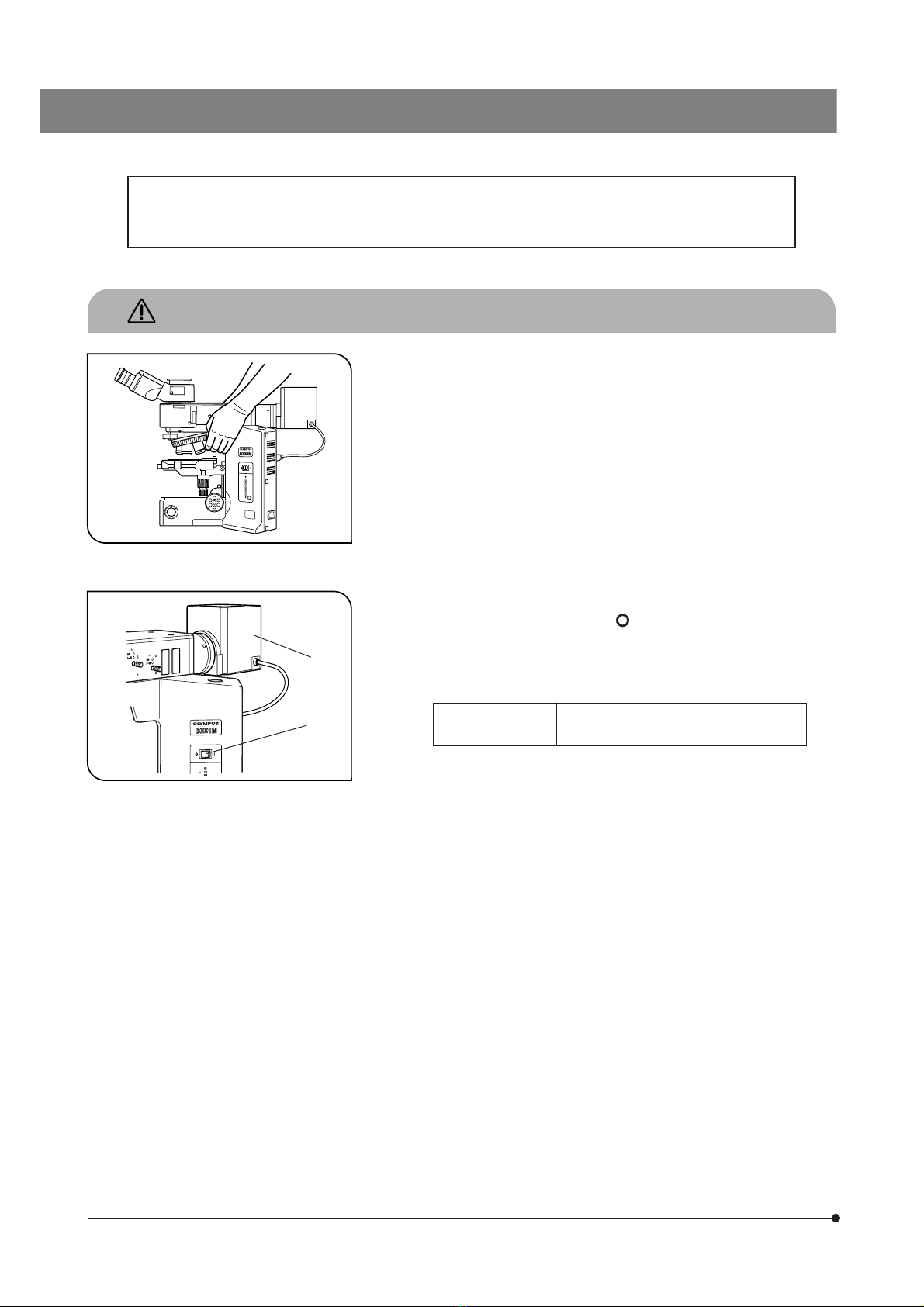
2. When moving the microscope, carefully carry it with the grasping part on
the arm as shown in Fig. 1 (Weight: approx. 15 kg).
#Damage to the microscope will occur if you grasp it by other parts
including the stage, lamp socket or tube.
#Before transporting the microscope, be sure to remove the speci-
men and eyepieces so that they will not drop. Also remove other
modules attached to the microscope because they increase the
system weight.
3. The surface of the lamp housing @ becomes very hot during operation.
Before installing the lamp housing, be sure to reserve enough space
around, particularly above, the lamp housing.
4. To avoid potential shock hazards and burns when replacing the light
bulb, set the main switch ² to “ ” (OFF) then disconnect the power
cord from the wall outlet in advance. Whenever you replace the bulb
during use or right after use, allow the lamp housing @ and bulb to cool
before touching (Fig. 2).
Fig. 1
Fig. 2
@
²Designated
halogen bulbs 12V100WHAL-L (PHILIPS 7724)
12V50WHAL-L (LIFE JC)
#The microscope also incorporates a fuse (this should be replaced
by the manufacturer or authorized agent).
5. Always use the power cord provided by Olympus. If no power cord is
provided, please select the proper power cord by referring to the chapter
“PROPER SELECTION OF THE POWER SUPPLY CORD” at the end of
this instruction manual. If the proper power cord is not used, product
safety and performance cannot be guaranteed.
6. Always ensure that the grounding terminal of the microscope and that
of the wall outlet are properly connected. If the equipment is not grounded,
Olympus can no longer warrant the electrical safety and performance of
the equipment.
7. Never insert metal objects, etc. into the air vents of the microscope frame
as this could result in electrical shock and personal injury.
8. The microscope system will be unstable when its height is increased by
attached accessories. Take proper measures so that the system will not
topple down.

2
BX51M
Symbol Explanation
The following symbols are found on the microscope. Study the meaning of the symbols and always use the equip-
ment in the safest possible manner.
Indicates that the surface becomes hot, and should not be touched with bare hands.
Before use, carefully read the instruction manual. Improper use could result in personal injury to
the user and/or damage to the equipment.
Indicates that the main switch is ON.
Indicates that the main switch is OFF.
Warning engraving/stickers are placed at parts where special precaution is required when handling and using the
microscope. Always heed the warnings.
Warning engraving
position
Lamp housing (U-LH100-3)
(Warning against high temperature)
l
Safety Symbols
Warnings
1Getting Ready
1. A microscope is a precision instrument. Handle it with care and avoid subjecting it to sudden or severe impact.
2. Do not use the microscope where it is subjected to direct sunlight, high temperature and humidity, dust or vibrations. (For
the operating conditions, refer to chapter 6, “SPECIFICATIONS”.)
3. The BX51M can be used with an intermediate attachment such as a U-CA magnification changer or U-EPA2 eyepoint
adjuster.
2Maintenance and Storage
1. To clean the lenses and other glass components, simply blow dirty away using a commercially available blower and wipe
gently using a piece of cleaning paper (or clean gauze).
If a lens is stained with fingerprints or oil smudges, wipe it gauze slightly moistened with commercially available absolute
alcohol.
!Since the absolute alcohol is highly flammable, it must be handled carefully.
Be sure to keep it away from open flames or potential sources of electrical sparks –– for example, electrical
equipment that is being switched on or off.
Also remember to always use it only in a well-ventilated room.
2. Do not attempt to use organic solvents to clean the microscope components other than the glass components. To clean
them, use a lint-free, soft cloth slightly moistened with a diluted neutral detergent.
3. Never attempt to disassemble any part of the microscope.
4. When not using the microscope, make sure that the lamp socket has cooled down sufficiently and then cover the
microscope with a dust cover.
5. When disposing of the microscope, check the ordinances and rules of your local authority and follow them.

3
3Caution
If the microscope is used in a manner not specified by this manual, the safety of the user may be imperiled. In addition,
the equipment may also be damaged. Always use the equipment as outlined in this instruction manual.
The following symbols are used to set off text in this instruction manual.
!: Indicates that failure to follow the instructions in the warning could result in bodily harm to the
user and/or damage to equipment (including objects in the vicinity of the equipment).
# : Indicates that failure to follow the instructions could result in damage to equipment.
} : Indicates commentary (for ease of operation and maintenance).

4
BX51M
1
NOMENCLATURE
}If you have not yet assembled the microscope, read chapter 8, “ASSEMBLY” (pages 27 to 29).
}This illustration shows the BX-51RF microscope frame with the BX-RLA2 reflected light brightfield/darkfield illuminator in-
stalled on it. For the nomenclature of the BX-URS2 universal illuminator, please refer to its instruction manual.
I
O
Polarizer insertion slot (Page 17)
Analyzer insertion slot
(Page 17)
Interpupillary distance
adjustment scale (Page 15)
Diopter adjustment ring
(Page 15)
Mirror selector lever (Page 9)
ND filter knob (Page 11)
DIC slider insertion slot
(Page 18)
Stage plate (Page 12)
Fine adjustment knob (Page 8)
Pre-focusing lever (Page 9)
Brightness adjustment knob (Page 7)
Light path selector knob (Page 16)
FS centering screw (Page 10)
Field iris diaphragm (FS) knob (Page 10)
Filter insertion slot (Page 11)
Allen screwdriver
AS centering screw
(Page 10)
Aperture iris diaphragm
(AS) knob (Page 10)
Main switch (Page 1)
Lamp voltage indicator
(Page 7)
Light intensity preset
switch (Page 7)
Light intensity preset adjustment
screw (Page 7)
Y-axis knob (Page 13)
X-axis knob (Page 13)
Coarse adjustment knob (Page 8)
Coarse adjustment tension adjustment ring (Page 8)
(Detachable)
(Lamp voltage adjustment knob)
#The filter should be inserted
from the left.
(accommodation
position)

5
REFLECTED LIGHT BRIGHTFIELD/DARKFIELD
OBSERVATION PROCEDURE
}The following flow shows the basic operating procedure for reflected light brightfield or darkfield observation. The operating
procedures for polarized light and Nomarski DIC observations will be described separately in their descriptions.
(Controls Used) (Page)
Select the brightfield (BF) or darkfield (DF) ob-
servation.
Set the main switch to “ I” (ON).
Disengage the analyzer, polarizer,
filter, etc. from the light path.
Check interlocking of the ND filter.
Select the light path (trinocular tube only).
Place the specimen on the stage.
Engage the 10X objective in the light path.
Bring the specimen in focus.
Adjust the brightness.
Adjust the interpupillary distance.
Adjust the diopter.
Adjust the aperture iris diaphragm and field iris
diaphragm.
} Open both iris diaphragms in case of DF ob-
servation.
Engage the desired objective in the light path
and bring the specimen in focus.
Insert the required filters.
Adjust the brightness.
Start observation.
@ Mirror selector lever (P. 9)
² Main switch
³ ND filter knob (P. 11)
| Light path selector knob (P. 16)
ƒ Stage plate (P. 12)
… X/Y-axis knobs (P. 13)
† Revolving nosepiece
‡ Coarse/fine adjustment knobs (P. 8)
Š Brightness adjustment knob (P. 7)
‰ Binocular tube (P. 15)
‹ Diopter adjustment ring (P. 15)
Œ AS knob (P. 10)
™ FS knob (P. 10)
† Revolving nosepiece
‡ Coarse/fine adjustment knobs (P. 8)
š Filter insertion slot (P. 11)
Š Brightness adjustment knob (P. 7)

6
BX51M
} Make a photocopy of the observation procedure pages and post it near your microscope.
@
I
O
²
³
|
ƒ
…
†
‡
Š
‰
‹
Œ
™
š
Insertion from the left
‡

7
USING THE CONTROLS
3-1 Base
1Voltage Indication (Fig. 3)
1. Turn the brightness adjustment knob @ clockwise to increase the volt-
age and make illumination brighter.
2. The numerals on the left of the lamp voltage LEDs ² indicate the ap-
proximate voltage.
2Using the Light Intensity Preset Switch (Fig. 4)
}The light intensity preset switch @ makes it possible to limit the light
intensity to a preselected level regardless of the position of the bright-
ness adjustment knob. The light intensity preset switch has been preset
before factory shipment to a position which can provide optimum color
reproduction when the U-25LBD filter is engaged in the light path (approx.
9 V mark).
1. Press the light intensity preset switch @ to the ON position. (The switch
lights when it is ON.)
2. Using a small flat-blade screwdriver, turn the preset adjustment screw ²
to obtain the required light intensity. Turning the screw clockwise increases
brightness.
3. When the light intensity preset switch is set to OFF, the brightness returns
to the level set by the brightness adjustment knob.
}While the light intensity preset switch is ON, turning the brightness ad-
justment knob does not affect brightness.
Fig. 3
Fig. 4
@²
@
²

8
BX51M
3-2 Focusing Block
1Adjusting the Focus (Fig. 5)
The coarse adjustment knob @ and fine adjustment knob ² are de-
signed to raise the stage (i.e. to let the specimen approach the objective)
when they are rotated in the direction of the arrows.
2Replacing the Fine Adjustment Knob (Fig. 6)
#The fine adjustment knob has been attached on the right side at the
factory.
}The fine adjustment knob is designed detachable to prevent interference
with hand during manipulation of the stage feed knobs. Usually attach
the knob on the opposite side to the stage feed knobs.
1. Loosen the clamping screw @ using the Allen screwdriver, and remove
the fine adjustment knob ².
2. Remove the seal from the fine adjustment knob screw hole on the other
side and attach the knob by reversing the removal procedure.
3. Attach one of the provided seals on the screw hole | of the removed
fine adjustment knob.
}The fine adjustment dial ³ can be operated with your fingertip or finger
surface.
3
Adjusting the Coarse Adjustment Knob Tension
(Fig. 7)
#The rotation tension of the coarse adjustment knob should be ad-
justed using the tension adjustment ring.
The coarse adjustment knob tension is preadjusted for easy use. How-
ever, if desired, you can change the tension using the tension adjust-
ment ring @. Turning the ring in the direction of the arrow increases
tension, and vice versa.
The tension is too low if the objective drops by itself or focus is quickly
lost after adjustment with the fine adjustment knob. In this case, turn the
ring in the direction of the arrow to increase tension.
Fig. 5
Fig. 6
Fig. 7
@
@
²
@
²
|
@
³

9
4Pre-focusing Lever (Fig. 8)
}The pre-focusing lever ensures that the objective does not come in con-
tact with the specimen and simplifies focusing.
After focusing on the specimen with the coarse adjustment knob, turn
this lever @ in the direction of the arrow and lock; the upper limit of
coarse adjustment movement is set at the locked position.
After changing a specimen, refocusing is easily accomplished by rotat-
ing the coarse adjustment knob to reach the pre-focused position, then
making fine adjustments with the fine adjustment knob.
}Stage movement with the fine adjustment knob is not locked.
# If the pre-focusing lever is locked, the stage cannot be lowered to
the lower limit.
3-3 Reflected Light Brightfield/Darkfield Illuminator (BX-RLA2)
}For the BX-URA2 universal illuminator, please refer to its instruction manual.
1Selecting the Light Path (Fig. 9)
Slide the mirror selector lever @ toward the indication of the mirror for the
desired observation method.
BF: Reflected light brightfield observation
DF: Reflected light darkfield observation
# Be sure to slide the mirror selector lever until it contacts the stopper
position.
Effects of Dummy Slider
The dummy slider ² has been installed on the revolving nosepiece at
the factory. It can be replaced by loosening the clamping knob ³ when
a DIC prism is to be used. However, in observations other than DIC, be
sure to push in the dummy slider in order for prevention of flare.
Fig. 8
Fig. 9
@
@
²
³

10
BX51M
2Centering the Field Iris Diaphragm (FS) (Fig. 10)
1. Slide the mirror selector lever @ to “BF”.
2. Engage the 10X objective by rotating the revolving nosepiece, place the
specimen on the stage and adjust approximate focusing.
3. Pull out the FS knob ² on the reflected light illuminator to reduce the
aperture iris diaphragm a little.
4. Rotate the two FS centering screws ³ using the Allen screwdriver to
adjust so that the field iris image becomes concentric with the field of
view.
5. While pushing in the FS knob ², open the field iris diaphragm until the
field iris image inscribes the field of view. If the image is found to be
eccentric, adjust the centering again.
6. Open the field iris so that its image is almost the same size as (i.e. sub-
scribes) the field of view.
Using the Field Iris Diaphragm
· In reflected light brightfield observation
The field iris diaphragm adjusts the illuminated area to obtain an image
with high contrast.
According to the objective in use, adjust the FS knob ² of the reflected
light illuminator until the iris image circumscribes the field of view to
block unnecessary light.
· In reflected light darkfield observation
The field iris diaphragm must be opened by pushing in the FS knob ².
Field iris diaphragm image
3Centering the Aperture Iris Diaphragm (AS) (Fig. 11)
1. Slide the mirror selector lever @ to “BF”.
2. Engage the 10X objective by rotating the revolving nosepiece, place the
specimen on the stage and adjust approximate focusing.
3. Remove the eyepiece, look into the eyepiece sleeve and pull the AS
knob ² so that the aperture is about 70%.
4. If the center of the iris diaphragm is deviated, center it by rotating the two
AS centering screws ³ using the Allen screwdriver.
Aperture iris image
Using the Aperture Iris Diaphragm
· In reflected light brightfield observation, optimum observation is gen-
erally possible by setting the aperture to between 70% and 80% of the
aperture number of the objective.
·Inreflected light darkfield observation, the aperture must be fully opened
by pushing in the AS knob ².
}With some specimens, an image with high contrast and little flare may
sometimes be obtained when the aperture is slightly closed. It is there-
fore recommended to also try a slightly closed aperture.
Fig. 10
Fig. 11
@
²
³
Field of view of eyepiece
@
²
³
|
70%
30%

11
4Using the ND Filter Knob (Fig. 12)
}The ND filter is interlocked with the brightfield (BF) light path switching so
it can be engaged or disengaged according to the mirror selector lever
@. The ND filter makes it possible to reduce the glare when darkfield (DF)
is switched to brightfield (BF).
Releasing Interlocking
}The ND filter knob has been interlocked at the factory.
}If brightness is not enough during brightfield, DIC or other observation,
the interlocking can be released.
1. Loosen the screw interlocking the ND filter by inserting the Allen screw-
driver into the hole ² on the left side of the reflected light illuminator.
2. Now the interlocking is released and the ND filter knob (| in Fig. 11) is
active. Pull the lever out to disengage the ND filter from the light path.
5 Using the Filters (Fig. 13)
}Engage the optimum filter sliders for the purpose of observation in the
two filter insertion slots @. Be sure to engage from the left side.
The first click position is the idle position and the second click engages
the filter in the light path.
Usable Filters Applications
U-25LBD
(Color temperature conver-
sion filter)
Turns the illumination light into daylight.
Used in general observations and color pho-
tography.
U-25IF550
(Green filter)
Enhanced contrast in monochrome obser-
vation.
Used in monochrome photography.
U-25Y48
(Yellow filter)
Contrast filter for observation of semicon-
ductor wafers.
U-25ND50-2 (Light intensity
adjustment filter)
Adjusts the brightness of the light source.
(Transmittance: 50%)
U-25ND6-2 (Light intensity
adjustment filter)
Adjusts the brightness of the light source.
(Transmittance: 6%)
U-25FR
(Frost filter)
Reduces irregularity in the illumination field,
but also reduces the brightness.
U-25L42
(UV cut filter)
Cuts ultraviolet rays. Used to prevent the po-
larizer from being burned by a high-inten-
sity light source.
Fig. 12
Fig. 13
@
²
@
U-25ND25-2 (Light intensity
adjustment filter)
Adjusts the brightness of the light source.
(Transmittance: 25%)

12
BX51M
3-4 Stage
1Placing the Specimen
}The maximum load capacities are as follows.
· Stage: 1.5 kg
· Stage plate: 500 g (U-SVRM/SVLM)
1 kg (U-SIC4R2/SIC4L2)
#Do not place a specimen which is heavier than above. Otherwise,
difficulty in stage movement or wear will result.
With the U-MSSP or U-MSSP4 Stage Plate
Place the specimen on the stage plate @ .
}The specimen should be parallel and planar. Otherwise, the reflected
light cannot reach the objective, rendering observation impossible.
}When observing very large specimens, remove the slide holder and place
the specimen directly on the stage.
[ U-SIC4R2/SIC4L2 Stage Only ]
Observation with the U-WHP2 Wafer Holder Plate (Fig. 15)
1. Place the BH2-WHR43 rotary wafer holder (for 3- or 4-inch) ² on the U-
WHP2 wafer holder plate @.
2. Place a 3-inch or 4-inch wafer on the BH2-WHR43 and observe the wa-
fer.
The wafer holder plate can be rotated with the knob ³.
[ U-SIC4R2/SIC4L2 Stage Only ]
Observation with the U-MSSPG Glass Holder Plate (Fig. 16)
}If the microscope is equipped with transmitted light illumination, trans-
parent specimens can also be observed.
1. Place the glass plate ² gently on the glass holder plate @.
2. Place a specimen or transparent specimen and observe it.
Fig. 14
Fig. 15
Fig. 16
@
@
²
³
@
²

13
2Adjusting the X/Y-Axis Knob Tension (Fig. 17)
}This mechanism is provided only with the U-SVRM/SVLM stage.
1. Hold the X-axis knob @ and slide up the Y-axis knob ² up to expose the
adjustment knobs.
2. Turning the X-axis adjustment knob ³ or Y-axis adjustment knob | clock-
wise (in the direction of the arrow) increases the tension and counter-
clockwise decreases it.
# If the tension is adjusted too tight, a creaking sound may be heard
during stage travel, and the stage stopping accuracy may be imper-
iled.
CAUTION After long hours of use, the stage guide may be devi-
ated and the stage travel range may be decreased.
However, this is not malfunction and can be corrected
easily as described below.
[Treatment] X-axis direction: Hold the specimen holder and move the stage
guide to the left and right so that it hits the
stoppers.
Y-axis direction: Hold the upper stage and move it to the front
and rear so that it hits the stoppers.
Rubber Stage Knob Caps (Optional)
}When the stage feed knobs of the U-SVRM/SVLM are fitted with the rub-
ber knob caps, the knobs can be adjusted without slipping and fine
adjustment is possible by holding the knobs with a very light force. The
rubber knob caps also reduces fatigue after long hours of operation.
The U-SHGT thick type (thickness 5 mm) and U-SHG thin type (thickness
2 mm) rubber knob caps are available.
To attach the knob rubber caps:
First fit the larger rubber knob cap to the Y-axis (upper) knob from below
it, then fit the smaller rubber knob cap to the X-axis (lower) knob from
below it.
3Using the Y-Axis Lock Lever (Fig. 18)
}This mechanism is provided only with the U-SIC4R2/SIC4L2 stage.
1. When the Y-axis lock lever @ is locked by setting the lever in the direction
of the arrow, the Y-axis movement is locked, making it possible to scan
only in the X-axis direction.
2. To release the lock, return the lever to the original position.
# If the lock lever is released incompletely, the lever will be worn out,
making locking impossible or causing dust.
Fig. 17
Fig. 18
²
|
³
@
@

14
BX51M
4Rotating the Stage (Fig. 19)
#The U-SIC4R2/SIC4L stage cannot be rotated.
1. Slightly loosen the stage clamping screw @ using the Allen screwdriver.
2. The stage can be rotated both clockwise and counterclockwise while
holding the stage.
#A click may be heard and felt during rotation. However, this is due to
the construction of the substage and does not indicate a malfunc-
tion.
}The angle of rotation varies depending on the knobs.
Angle of Rotation
Clockwise Counterclockwise
Right-hand knobs 230° 20°
Left-hand knobs 20° 230°
5Adjusting the Stage Height (Fig. 20)
}By lowering the position of the stage, the microscope will accommo-
date thick or metallurgical specimens with maximum height of 65 mm
(62 mm when a stage plate is used).
!When the stage holder clamping screw @ is loosened, the stage ²
will fall. To prevent this, be sure to support the stage during the height
adjustment.
1. Hold and support the stage ² and loosen the stage holder clamping
screw @ using the Allen screwdriver.
2. Move the stage up or down to the desired height, and tighten the screw
tightly.
Fig. 19
Fig. 20
@
²@

15
3-5 Observation Tube
1Adjusting the Interpupillar Distance (Fig. 21)
While looking through the eyepieces, adjust for binocular vision until the
left and right fields of view coincide completely. The index dot · indicates
the interpupillary distance.
}Note your interpupillary distance so that it can be quickly duplicated.
2Adjusting the Diopter (Fig. 22 & 23)
1. Looking through the eyepiece without the diopter adjustment ring, rotate
the coarse and fine adjustment knobs to bring the specimen into focus.
2. Looking through the eyepiece with the diopter adjustment ring @, turn it
to focus on the specimen. (Fig. 22)
Using a Finder Eyepiece
1. Looking through the right eyepiece with your right eye, turn the top of the
eyepiece ² until a clearly defined double crosslines can be seen in the
field of view. (Figs. 22 & 23)
2. Looking through the right eyepiece, rotate the coarse and fine adjust-
ment knobs to bring the specimen and double crosslines into simulta-
neous focus.
3. Looking through the left eyepiece with your left eye, turn the diopter ad-
justment ring @ to focus on the specimen.
Using a Super Widefield Observation Tube
The operation is basically identical to the above. However, as the left
eyepiece does not have the diopter adjustment ring, the focus should be
adjusted by rotating the top of the right eyepiece.
3Using the Eye Shades (Fig. 24)
When Wearing Eyeglasses
Use with the eye shades in the normal, folded-down position. This will
prevent the eyeglasses from being scratched.
When Not Wearing Eyeglasses
Extend the folded eye shades in the direction of the arrow to prevent
extraneous light from entering between the eyepieces and eyes.
Fig. 21
Fig. 22
Fig. 23
Fig. 24
@
²

16
BX51M
4Using Eyepiece Micrometer Disks (Fig. 25)
Eyepiece micrometer disks can be inserted into the WHN10X-H (or
WHN10X) eyepieces.
However, if the eyepiece does not have the helicoid adjustment facility
and your eyesight is poor, you may have difficulties in focusing on the
eyepiece micrometer disk. In this case, it is recommended to look into
the eyepiece through your eyeglasses.
Use 24 mm dia. x 1.5 mm micrometer disks.
Following Fig. 25, remove the micrometer mounting frame ² from the
eyepiece and place a micrometer disk @ into the mounting frame.
Re-attach the micrometer mounting frame in the original position.
Fig. 25
@
²
5
Selecting the Light Path of theTrinocular Tube
(Fig. 26)
Slide the light path selector knob @ to select the desired light path.
Trinocular
Tube
Light Path Selector Position
Pushed In Intermediate Pulled Out
U-TR30-2 Binocular 100% Binocular 20% TV, photo 100%
U-SWTR-3 TV, photo 80%
U-ETR3 Binocular 100% TV, photo 100%
U-SWETR
U-SWETTR2 Binocular 100% Binocular 20%
TV, photo 80%
6
Adjusting the Tilt (with the U-TBI3/SWETTR2)
(Fig. 27)
}Adjust the height and tilt angle of the observation tube to obtain the most
comfortable viewing position.
Holding the binocular section with both hands, raise or lower it to the
desired position.
#Never attempt to force the binocular section past the upper or lower
stop position. Applying excessive force could destroy the limiting
mechanism.
#The U-TBI3 cannot be used in combination with any intermediate
attachment.
#When darkfield observation of scratches and/or dust on a mirror
surfaces is performed with the U-TBI3, ghost images may appear.
With the U-ETBI (Fig. 28)
The U-ETBI is an ergonomical observation tube with normal field ca-
pable of tilting adjustment with an erect image. The eyepiece position
can be adjusted by 45 mm toward the front and rear.
Fig. 26
Fig. 27
Fig. 28
@

17
OBSERVATION METHODS (Using BX-RLA2)
}For the observation methods with the BX-URA2 universal illuminator, refer to its instruction manual.
4-1 Reflected Light Brightfield/Darkfield Observation
See “REFLECTED LIGHT BRIGHTFIELD/DARKFIELD OBSERVATION PROCEDURE” on page 5.
4-2 Reflected Light Nomarski DIC (Differential Interference Contrast) Observation
# The performance of polarizer may deteriorate when it has been exposed to light for a long period (about continu-
ous 2000 hours). If this happens, replace the polarizer.
# When performing sensitive color observation using the U-DICRH DIC slider, combine the U-POTP3 polarizer.
# When using the high-intensity light source, be sure to use the U-25L42 filter to prevent the polarizer from being
burnt.
1Setting the Analyzer and Polarizer (Fig. 29)
# In the current step, do not engage the DIC slider in the light path.
1. Bring the specimen in approximate focus using the 10X or 20X objective.
2. Remove the cover to enable installation of the U-AN360-3 analyzer. Then
put the analyzer @ in the insertion slot.
3. Insert the U-PO3 or U-POTP3 polarizer ² so that the surface with indica-
tion comes on the front, and engage the polarizer in the light path.
4. Rotate the analyzer rotating dial ³ to find the position where the field of
view is darkest.
}An approximate cross-Nicol position can be obtained by setting the in-
dex on the dial ³ on the outer side. Fine-adjust the dial by rotating it near
this position to find the position where the field of view is darkest.
Using the Coupling Plate (Fig. 30)
When the U-AN360-3 analyzer ƒ and U-PO3 or U-POTP3 polarizer … are
coupled by using the coupling plate | provided with the polarizer and
tightening the clamping knobs on it, the analyzer and polarizer can be
engaged or disengaged in the light path together.
Fig. 29
Fig. 30
@
²
³
ƒ
…
|
Table of contents
Other Olympus Microscope manuals

Olympus
Olympus Discover FV10i Owner's manual

Olympus
Olympus SZX16 User manual

Olympus
Olympus BH2-CH Substage User manual

Olympus
Olympus MIC-D User manual

Olympus
Olympus VS120 Owner's manual

Olympus
Olympus SZX7 User manual

Olympus
Olympus CX21LED User manual

Olympus
Olympus BX43 User manual

Olympus
Olympus BX2 SERIES User manual

Olympus
Olympus Fluoview FV1000 Manual

Olympus
Olympus BHT User manual

Olympus
Olympus JM User manual

Olympus
Olympus CX40 User manual

Olympus
Olympus fsx100 User manual

Olympus
Olympus IX70 User manual

Olympus
Olympus BX51WI User manual

Olympus
Olympus CHBS User manual

Olympus
Olympus CX43-RFAB User manual

Olympus
Olympus SZX7 User manual

Olympus
Olympus FV3000 User manual