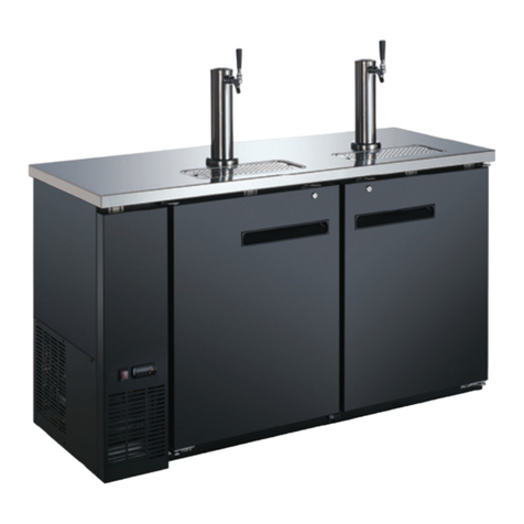
Omcan BC-CN-0152 User manual

Revised - 08/05/2022
Toll Free: 1-800-465-0234
Fax: 905-607-0234
Email: [email protected]
www.omcan.com
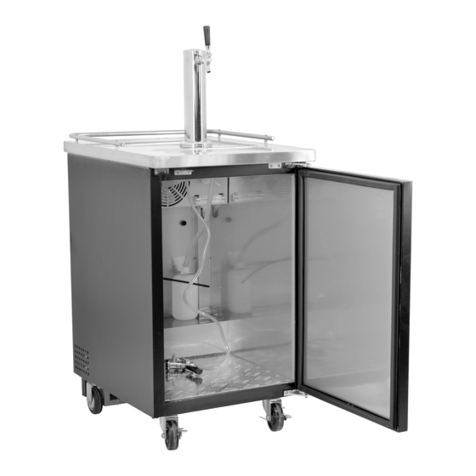
Beer Keg Cooler
Model BC-CN-0152
Item 46500
Instruction Manual

2
Page
-------------------------------------------------------------------------------------------- 3
--------------------------------------------------------------------------- 4 - 5
--------------------------------------------------------------------------- 5 - 8
-------------------------------------------------------------------------- 8
-------------------------------------------------------------------------------------- 9 - 12
------------------------------------------------------------------------------------- 12 - 14
--------------------------------------------------------------------------------------- 15
---------------------------------------------------------------------------- 16 - 18
---------------------------------------------------------------------------- 19
------------------------------------------------------------------------------------------- 20 - 22
---------------------------------------------------------------------------- 23
Table of Contents
Section
Disclaimer
General Information
Safety and Warranty
Technical Specications
Installation
Operation
Maintenance
Parts Breakdown
Electrical Schematics
Notes
Warranty Registration
Model BC-CN-0152

3
Disclaimer
OMCAN IS NOT RESPONSIBLE FOR
ANY DAMAGES DUE TO WATER LEAKS.
WARRANTY FOR WATER LEAKS IS VOID
IF THE WICKING PAD IS NOT REPLACED
EVERY SIX MONTHS, AND IF THE AMBIENT
ROOM TEMPERATURE EXCEEDS 75°F
AND 55% RELATIVE HUMIDITY, AND THE
APPLIANCE DRAIN IS NOT CONNECTED
DIRECTLY TO THE FLOOR DRAIN.

4
General Information
Omcan Manufacturing and Distributing Company Inc., Food Machinery of America, Inc. dba Omcan
and Omcan Inc. are not responsible for any harm or injury caused due to any person’s improper or
negligent use of this equipment. The product shall only be operated by someone over the age of 18, of
sound mind, and not under the inuence of any drugs or alcohol, who has been trained in the correct
operation of this machine, and is wearing authorized, proper safety clothing. Any modication to the
machine voids any warranty, and may cause harm to individuals using the machine or in the vicinity of
the machine while in operation.
CHECK PACKAGE UPON ARRIVAL
Upon receipt of an Omcan shipment please inspect for external damage. If no damage is evident on the
external packaging, open carton to ensure all ordered items are within the box, and there is no concealed
damage to the machine. If the package has suered rough handling, bumps or damage (visible or concealed),
please note it on the bill of lading before accepting the delivery and contact Omcan within 24 hours, so we may
initiate a claim with the carrier. A detailed report on the extent of the damage caused to the machine must be
lled out within three days, from the delivery date shown in the shipping documents. Omcan has no recourse
for damaged products that were shipped collect or third party.
Before operating any equipment, always read and familiarize yourself with all operation and safety
instructions.
Omcan would like to thank you for purchasing this machine. It’s of the utmost importance to save
these instructions for future reference. Also save the original box and packaging for shipping the
equipment if servicing or returning of the machine is required.
---------------------------------------------------------------------------------------------------------------------------------------------------
Omcan Fabrication et distribution Companie Limité et Food Machinery d’Amerique, dba Omcan et
Omcan Inc. ne sont pas responsables de tout dommage ou blessure causé du fait que toute personne
ait utilisé cet équipement de façon irrégulière. Le produit ne doit être exploité que par quelqu’un de
plus de 18 ans, saine d’esprit, et pas sous l’inuence d’une drogue ou d’acohol, qui a été formé pour
utiliser cette machine correctement, et est vêtu de vêtements de sécurité approprié. Toute modication
de la machine annule toute garantie, et peut causer un préjudice à des personnes utilisant la machine
ou des personnes à proximité de la machine pendant son fonctionnement.
VÉRIFIEZ LE COLIS DÈS RÉCEPTION
Dès réception d’une expédition d’Omcan veuillez inspecter pour dommages externes. Si aucun dommage
n’est visible sur l’emballage externe, ouvrez le carton an de s’assurer que tous les éléments commandés
sont dans la boîte, et il n’y a aucun dommage dissimulé à la machine. Si le colis n’a subi aucune mauvaises
manipulations, de bosses ou de dommages (visible ou cachée), notez-le sur le bond de livraison avant
d’accepter la livraison et contactez Omcan dans les 24 heures qui suivent, pour que nous puissions engager
une réclamation auprès du transporteur. Un rapport détaillé sur l’étendue des dommages causés à la machine
doit être rempli dans un délai de trois jours, à compter de la date de livraison indiquée dans les documents
d’expédition. Omcan n’a aucun droit de recours pour les produits endommagés qui ont été expédiées ou cueilli
par un tiers transporteur.

5
Safety and Warranty
General Information
BEFORE USING YOUR BEER DISPENSER
Remove the exterior and interior packing. Check to be sure you have all of the following parts:
• 1 Safety Guard Rail.
• 1 Drip Tray (2 Pieces).
• 1 CO2 Cylinder Support.
• 1 CO2 Regulator (Box).
Avant d’utiliser n’importe quel équipement, toujours lire et vous familiariser avec toutes les opérations
et les consignes de sécurité.
Omcan voudrais vous remercier d’avoir choisi cette machine. Il est primordial de conserver ces
instructions pour une référence ultérieure. Également conservez la boîte originale et l’emballage pour
l’expédition de l’équipement si l’entretien ou le retour de la machine est nécessaire.
---------------------------------------------------------------------------------------------------------------------------------------------------
Omcan Empresa De Fabricacion Y Distribucion Inc. Y Maquinaria De Alimentos De America, Inc. dba
Omcan y Omcan Inc. no son responsables de ningun daño o perjuicío causado por cualquier persona
inadecuada o el uso descuidado de este equipo. El producto solo podra ser operado por una persona
mayor de 18 años, en su sano juicio y no bajo alguna inuencia de droga o alcohol, y que este ha sido
entrenado en el correcto funcionamiento de esta máquina, y ésta usando ropa apropiada y autorizada.
Cualquier modicación a la máquina anúla la garantía y puede causar daños a las personas usando la
máquina mientras esta en el funcionamiento.
REVISE EL PAQUETE A SU LLEGADA
Tras la recepcion de un envio Omcan favor inspeccionar daños externos. Si no hay daños evidentes en el
empaque exterior, Habra el carton para asegurararse que todos los articulos solicitados ésten dentro de la
caja y no encuentre daños ocultos en la máquina. Si el paquete ha sufrido un manejo de poco cuidado, golpes
o daños (visible o oculto) por favor anote en la factura antes de aceptar la entrega y contacte Omcan dentro
de las 24 horas, de modo que podamos iniciar una reclamación con la compañia. Un informe detallado sobre
los daños causados a la máquina debe ser llenado en el plazo de tres días, desde la fecha de entrega que se
muestra en los documentos de envío. Omcan no tiene ningun recurso por productos dañados que se enviaron
a recoger por terceros.
Antes de utilizar cualquier equipo, siempre lea y familiarizarse con todas las instrucciones de
funcionamiento y seguridad.
Omcan le gustaría darle las gracias por la compra de esta máquina. Es de la mayor importancia para
salvar estas instrucciones para futuras consultas. Además, guarda la caja original y el embalaje para el
envío del equipo si servicio técnico o devolución de la máquina que se requiere.

6
Safety and Warranty
• 1 CO2 Empty Cylinder(Box).
• 1 CO2 Air Line Hose (Red).
• 1 Beer Keg Coupler (Box).
• 1 Beer Tower.
• 1 Pull Handle (Beer Tower Faucet).
• 4 Plugs: For Guard Rail Holes.
• 1 Metal Plate For Cabinet Bottom.
• 2 Steel Wire Shelves.
• 1 Steel Clamp for Red Hose.
• 4 Castors (2 Front with Locks).
Before plugging in the keg cooler, let it stand upright for approximately 2 hours. This will reduce the possibility
of a malfunction in the cooling system from handling during transportation. Clean the interior surface with
lukewarm water using a soft cloth.
ELECTRICAL CONNECTION
WARNING: Improper use of the grounded plug can result in the risk of electrical shock. If the power
cord is damaged, have it replaced by an authorized service canter.
This Beer Dispenser should be properly grounded for your safety. The power cord of this Beer Dispenser is
equipped with a three-prong plug which mates with standard three prong wall outlets to minimize the possibility
of electrical shock.
Do not under any circumstances cut or remove the third ground prong from the power cord supplied.
Use of extension cords is not recommended.
This Beer Dispenser requires a standard 115/120-volt, 60Hz electrical outlet with three-prong ground
receptacle. The cord should be secured behind the Beer Dispenser and not left exposed or dangling to prevent
accidental injury.
Never unplug the Beer Dispenser by pulling the power cord. Always grip the plug rmly and pull straight out
from the receptacle.
WARNING: CO2 GAS CAN BE DANGEROUS! CO2 cylinders contain high-pressure compressed gas
which can be hazardous if not handled properly. Make sure you READ and UNDERSTAND the following
procedures for CO2 cylinders BEFORE INSTALLATION.
1. ALWAYS connect the CO2 cylinder to a regulator. Failure to do so could result in explosion with possible
injury when the cylinder valve is opened.
2. NEVER connect the CO2 cylinder directly to the product container.
3. ALWAYS follow correct procedures when cylinders are changed.
4. ALWAYS secure the cylinder in an upright position.
5. NEVER drop or throw a CO2 cylinder.

7
Safety and Warranty
6. ALWAYS keep a CO2 cylinder away from heat. Store extra cylinders in a cool place (preferably 70°F).
Securely fasten with a chain in an upright position when storing.
7. ALWAYS ventilate and leave the area immediately if CO2 leakage has occurred.
8. ALWAYS check the D.O.T. test date on the cylinder neck before installation. If over ve {5) years, do not
use, return cylinder to gas supplier.
9. NEVER connect a product container unless there are two (2) safety’s in the pressure system:
a. One at or on the CO2 regulator.
b. One at or on the product coupler or in the pressure gas line.
INSTALLATION OF BEER DISPENSER
• This appliance is designed to be free standing only, and should not be recessed or built-in.
• Place your Beer Dispenser on a oor that is strong enough to support the Beer Dispenser when it is fully
loaded.
• Allow 3 inches of space between the back and sides of the Beer Dispenser, which allows the proper air
circulation to cool the compressor.
• Locate the Beer Dispenser away from direct sunlight and sources of heat (stove, heater, radiator, etc.).
Direct sunlight may aect the acrylic coating and heat sources may increase electrical consumption.
Extreme cold ambient temperatures may also cause the Beer Dispenser not to perform property. This unit
is not designed for outside installation (ie: garages, porches, etc.)
• Avoid locating the Beer Dispenser in excessive humidity.
• Plug the Beer Dispenser into a dedicated, property installed-grounded wall outlet. Do not under any
circumstances cut or remove the third (ground) prong from the power cord. Any questions concerning
power and or grounding should be directed toward a certied electrician or an authorized service center.
• After plugging the appliance into a wall outlet, allow the unit to cool down for 2-3 hours before placing any
contents in the Beer Dispenser compartment.
RESIDENTIAL USERS: Vendor assumes no liability for parts or labor coverage for component failure
or other damages resulting from installation in non-commercial or residential applications. The right
is reserved to deny shipment for residential usage; if this occurs, you will be notied as soon as
possible.
1 YEAR PARTS AND LABOUR BENCH WARRANTY
Within the warranty period, contact Omcan Inc. at 1-800-465-0234 to schedule a drop o to either
an Omcan authorized service depot in the area, or to an Omcan Service warehouse to repair the
equipment.
Unauthorized maintenance will void the warranty. Warranty covers electrical and part failures not
improper use.
Please see https://omcan.com/disclaimer for complete info.

8
Safety and Warranty
WARNING:
The packaging components are classied as normal solid urban waste and can therefore be disposed of
without diculty.
In any case, for suitable recycling, we suggest disposing of the products separately (dierentiated
waste) according to the current norms.
DO NOT DISCARD ANY PACKAGING MATERIALS IN THE ENVIRONMENT!
Technical Specications
Model BC-CN-0152
Capacity 152 L / 5.37 cu.ft.
Electrical 115V / 60Hz / 1
Temperature Range 2 - 8°C / 35.6 - 46.4°F
Max Ambient Temp
Rating 24°C / 75°F
Foaming Components C - P
Refrigerant R600a
Keg Size Supported
20 L / 5 Gal
30 L / 7.75 Gal
58.5 L / 15.5 Gal
Weight 79.4 lbs. / 36 kgs.
Packaging Weight 88.2 lbs. / 40 kgs.
Dimensions 20.7” x 26.2” x 33.2” / 526 x 665 x 843mm
Packaging Dimensions 22.4” x 27.2” x 34.8” / 570 x 690 x 885mm
Item Number 46500

9
Installation
CASTOR BRAKE INSTALLATION
Install the four castors (2 locking castors at front) into the units bottom (four screw holes pre-supplied) Figure
(1) before installation. Figure (2) is the nal version.
INSTALLATION OF CO2 CYLINDER SUPPORT
Install the metal support provided onto the 4 studs located on the exterior back wall. Align the holes in the
support with the studs and push down rmly. (See Figure 1)
INSTALLATION OF CO2 CYLINDER
• The CO2 Cylinder does not come lled. The cylinder must be lled with CO2 prior to use.
• Install your fully charged cylinder into the support stand.
INSTALLATION OF CO2 REGULATOR
Attach the CO2 regulator to the cylinder by turning the regulator nut onto cylinder valve, making sure washer is
securely inserted into connecting nut. Tighten snug using an adjustable wrench (not supplied) and assure there
are no leaks. (See Figure 2)
INSTALLATION OF CO2 AIR LINE OUTSIDE CABINET
• Remove plug located at the exterior back (top left hand corner).
• Save it for later use if you decide to convert unit to a refrigerator.
• Insert the open end of the air line (red) line the cabinet through the uncovered hole. (See Figure 4)
INSTALLATION OF CO2 AIR LINE HOSE TO REGULATOR
• Attach the open end of the red hose to the hose barb connection on the regulator.
• Secure hose by using one clamp provided. Use pliers/screwdriver to tighten clamp to prevent leaks. (See
Figure 3)
INSTALLATION OF THE BEER TOWER
• Remove the top plug by twisting and pulling out, saving it for later use if you decide to convert unit to an all
refrigerator unit.
• Unravel the bear line (clear hose) from the tower and insert the beer line and wing nut through the
uncovered hole on top.
• Lock the beer tower assembly to the top and make sure to position the beer faucet so it is aligned with

10
Installation
the cabinet front (6 o-clock position). You accomplish this by aligning the bottom of the beer tower to the 3
grooves on the top cabinet and tighten by hand clockwise to properly lock.
• The plastic gasket, can be used to make the connection between the tower and the cooler tighter if needed.
If Beer Tower will not turn to lock in place, try removing the plastic gasket.
INSTALLATION OF PROTECTIVE METAL PLATE
This plate should always be installed when the keg is in place to protect against unnecessary damage to the
oor of the cabinet.
INSTALLATION OF THE BEER KEG
• Position the beer keg directly in front of the open door. Using keg handles only, carefully lift the beer keg.
(See Figure 5)
• To place the beer keg inside the cabinet, brace your knees behind the beer keg. Lift the front of the keg just
enough so the front edge of the keg is resting on the front edge of the Beer Dispenser bottom cabinet. (See
Figure 6)
• Grasp the keg handles and slide it all the way into the cabinet.
INSTALLATION OF THE KEG COUPLER
Insert the keg coupler provided into the locking neck of the beer keg and turn it clockwise to lock into position,
making sure the keg coupler is in the closed position. (See Figure 7)
INSTALLATION OF THE CO2 AIR LINE HOSE
Attach the end of the air line (red) hose provided to the hose connection on the keg coupler.
CONNECTING THE BEER TOWER TO COUPLER
• Make sure the washer is properly inserted into the wing nut.
• Make sure the small round bead is in place (dropped down into the top of the coupler).
• Make sure the ball retainer is in place on the coupler, with the “arms” down into the coupler.
• Place wing nut into the top of the coupler turning until tight.
HOW TO TAP A KEG OF BEER
• Make sure that the CO2 is turned o, and the Secondary valve on the regulator is in the “Closed” position.
• Pull out and release the pressure release valve on the Coupler to purge any air pressure.
• Make sure the beer tower faucet is in the closed position.
• Pull tapping handle out and press downward until it locks into position. (See Figure 8) The keg is now
tapped.
OPENING THE CO2 CYLINDER MAIN VALVE
• Make sure the secondary shut-o valve (shown in gure 9 in “Open” position) is closed. To open the main
CO2 cylinder valve, slowly turn the main valve counter-clockwise until fully open.
• Notice the needle on the regulator gauge start to climb.
ADJUSTING THE CO2 REGULATOR
The gauge monitors low internal keg pressure and should be adjusted to read between 10-12 psi. (See Figure
10). The pressure can be adjusted as needed.

11
Installation
• Release adjustment lock nut marked 2.
• Using a at screwdriver, turn regulator screw marked 3.
- To increase pressure, turn screw clockwise.
- To decrease pressure, turn screw counter-clockwise.
• Retighten lock nut marked 2.
• Open secondary shut o valve to let CO2 ow into the keg.
• Allow several minutes for the keg to properly pressurize. Regulator gauge may drop while this happens.
Note: Listen for hissing along all connections to identify if there are any leaks.
SPANNER FAUCET WRENCH (NOT INCLUDED)
Spanner faucet wrench (not provided) is for either removing or tightening the connection.
PLASTIC FAUCET LEVER
Attach the black plastic lever (pull handle) to the top of the faucet by tightening it by hand clockwise until the
end, holding in the silver nut underneath so it does not turn. If there is still a small drip from the faucet, you may
have tightened the plastic lever too much and may need to unscrew silver snug counter-clockwise one turn.
DISPENSING OF BEER
• Keep beer keg refrigerated at all times.
• Never allow beer lines to dry out.
• Use clean beer glassware before pouring.
• Hold glass at a 45° angle when 2/3 full, start to straighten glass as the glass lls.
• Always make sure the faucet handle is pushed all the way back.
Note: Keg sizes that can be used in your beer dispenser.
1/2 Barrel 59 Liters 15.5 gals. 1984 oz. 164/12-oz. Glass
1/4 Barrel 30 Liters 7.8 gals. 992 oz. 82/12-oz. Glass
1/6 Barrel 20 Liters 5.2 gals. 661 oz. 55/12-oz. Glass
1/8 Barrel 15 Liters 4.0 gals. 496 oz. 41/12-oz. Glass
Note: Our Beer dispenser accepts standard kegs up to 16-1/8” in diameter, and up to 23-3/8” in height.
Check with your distributor to make sure keg is correct size.

12
Installation
Operation
SETTING THE TEMPERATURE
The temperature is controlled by adjusting/setting the thermostat control knob. To start the unit and achieve
maximum cooling quickly;
• Turn the temperature control knob clockwise to the furthest (maximum) setting on the blue (wide) section of
the control dial. (Fig A)
• Allow the unit to run at this setting for 3-4 hours.
• When maximum cooling is achieved, turn back the temperature control knob to a moderate/medium
temperature.
• To turn o (no cooling) rotate the control knob to the “O” (o) position. (Fig.B.)

13
Operation
AUTOMATIC DEFROSTING
There is no need to defrost the Beer Dispenser. Defrost water collects and passes thru the drain outlet in the
rear wall into a tray located above the compressor, where it evaporates.
NOTE: If the unit is unplugged,power lost, or turned o; you must wait 3 to 5 minutes before restarting
the unit. If you attempt to restart before this time delay, the Beer Dispenser may not start.
CONVERTING TO AN “ALL REFRIGERATOR”
1. Turn o the control knob to the “OFF” position.
2. Close the main valve on the CO2 cylinder.
3. Close the secondary shut-o valve on the regulator pipe.
4. Close the connection between the beer keg and the keg coupler.
5. Drain any remaining beer from the lines.
6. Disconnect the beer line and CO2 air line from the keg coupler.
7. Remove the beer keg.
8. Remove the keg coupler.
9. Disconnect the air line from the CO2 cylinder.
10. Remove the CO2 air line from cabinet plug.
11. Replace the air line rear cabinet plug.
12. Remove the beer tower. Also pull the beer line thru the top of the cabinet.
13. Replace the top cabinet plug.
14. Adjust temperature as desired.
CHANGING THE REVERSIBLE DOOR
This Beer Dispenser has a door that can be set to open from the left or right side. The unit is delivered to you
with the door opening from the left side. To reverse the opening direction, please follow the instructions below.
Caution: To avoid personal injury to yourself and/or property, we recommend that someone assist you
during the door reversal process.
1. Undo the three screws in each bracket using the Phillips screwdriver.
2. Remove the screws and bracket. Place to one side.
3. Slide the fridge door down about 15cm (6”) and o the top hinge pin and lift away from the freezer.
4. Using the at bladed screw driver remove the pin from the top bracket. Replace it in the hinge bracket on
the opposite side.
5. Remove the screw from the side of the fridge where the bracket is to be re-tted.
6. Slide the fridge door back on to the top hinge, making sure it’s the right way up. Screw the bottom hinge
into place on the new side.
7. Check that the door is aligned horizontally and vertically and that the seals are closed on all sides before
nally tightening the bottom hinge. Re-adjust the leveling feet.

14
Operation

15
Maintenance
CLEANING YOUR BEER DISPENSER
• Turn the temperature control to “OFF”, unplug the Beer Dispenser, and remove the contents.
• Wash the inside surfaces with a warm water and baking soda solution. The solution should be about 2
tablespoons of baking soda to a quart of water.
• Wash the shelves and stand with a mild detergent solution.
• Wipe down any electrical controls with a dry cloth.
• Wash the outside cabinet with warm water and mild liquid detergent. Rinse well and wipe dry with a clean
soft cloth.
VACATION TIME
• Short vacations: Leave the Beer Dispenser operating during vacations of less than three weeks.
• Long vacations: If the appliance will not be used for several months, remove all contents and unplug the
power cord. Clean and dry the interior thoroughly. To prevent odor and mold growth, leave the door open
slightly.
MOVING YOUR BEER DISPENSER
• Remove all the contents.
• Securely tape down all loose items inside your Beer Dispenser.
• Tape the door shut.
• Be sure the Beer Dispenser stays secure in the upright position during transportation. Also protect outside
of Beer Dispenser with a blanket or similar item.

16
Parts Breakdown
Model BC-CN-0152 46500

17
Parts Breakdown
Model BC-CN-0152 46500

18
Parts Breakdown
Model BC-CN-0152 46500
Item No. Description Position Item No. Description Position Item No. Description Position
AG054 Door Assembly for 46500 1 AG080 Big Steel Wire Shelf for 46500 27 AG106 CO2 Hose Bushing for 46500 53
AG055 Hinge Plug for 46500 2 AG081 Grounding Screw for 46500 28 AG107 CO2 Cylinder Gasket for 46500 54
AG056 Door Gasket for 46500 3 AG082 Drip Tray Assembly for 46500 29 AG108 CO2 Cylinder Bracket Screw for 46500 55
AG057 Worktop for 46500 4 AG083 Drip Tray Screw for 46500 30 AG109 Left Worktop Rail for 46500 56
AG058 Fixing Plate for 46500 5 AG084 Compressor Support for 46500 31 AG110 Right Worktop Rail for 46500 57
AG059 Fixing Plate Screw for 46500 6 AG085 Foot Screw for 46500 32 AG111 Worktop Rail Screw for 46500 58
AG060 Hook Screw for 46500 7 AG086 Foot for 46500 33 AG112 CO2 Cylinder Bracket for 46500 59
AG061 Worktop Screw for 46500 8 AG087 Compressor Support Screw for 46500 34 AG113 Slide-Proof Pad for 46500 60
AG062 Upper Hinge Screw Assembly for 46500 9 AG088 Compressor Protector Cover for 46500 35 AG114 Beer Tray for 46500 61
AG063 Right Upper Hinge for 46500 10 AG089 Compressor Cover Screw for 46500 36 AG115 Beer Tray Shelf for 46500 62
AG064 Upper Door Spindle for 46500 11 AG090 Compressor Bushing for 46500 37 AG116 3” Tower Set (Single Outlet) for 46500 63
AG065 Left Upper Hinge for 46500 12 AG091 Compressor Rubber Washer for 46500 38 AG117 Plastic Handle for 46500 64
AG066 Beer Sleeve for 46500 13 AG092 Compressor Screw for 46500 39 AG118 Beer Tower Washer for 46500 65
AG067 Beer Dispenser Outer Collar C for 46500 14 AG093 Compressor for 46500 40 AG119 Beer Tower Fixed Screw for 46500 66
AG068 Thermostat Box for 46500 15 AG094 PTC Starter for 46500 41 AG120 Clamp for 46500 67
AG069 Thermostat Box Screw for 46500 16 AG095 Overload Protector for 46500 42 AG121 Gas Line for 46500 68
AG070 Thermostat Knob for 46500 17 AG096 PTC Cover for 46500 43 AG122 D-Keg Coupler for 46500 69
AG071 Thermostat for 46500 18 AG097 Filter for 46500 44 AG123 Spanner for 46500 70
AG072 Bottom Hinge Assembly for 46500 19 AG098 Evaporator for 46500 45 AG124 Spare Parts for 46500 71
AG073 Bottom Hinge Screw Assembly for 46500 20 AG099 Evaporator Screw for 46500 46 AG125 2.5 LBS CO2 Cylinder + Valve for 46500 72
AG074 Adjustable Foot for 46500 21 AG100 Beer Cover (Silk Printing) for 46500 47 AG126 CO2 Regulator (Single) for 46500 73
AG075 Beer Tank Support Rack for 46500 22 AG101 Beer Dispenser Outer Collar A for 46500 48 AG127 Castors (with Skid) for 46500 74
AG076 Beer Tank Support Rack Screw for 46500 23 AG102 Beer Dispenser Outer Collar for 46500 49 AG128 Castors Screw for 46500 75
AG077 Power Supply Cord Assembly for 46500 24 AG103 Worktop Screw for 46500 50 AG129 Castors Backing Plate for 46500 76
AG078 Small Steel Wire Shelf for 46500 25 AG104 Sleeve Plug for 46500 51 AG130 Castors for 46500 77
AG079 Wire Clamp Screw for 46500 26 AG105 CO2 Hose Bushing Screw for 46500 52

19
Electrical Schematics
Model BC-CN-0152 46500

20
Notes
________________________________________________________________________________________
________________________________________________________________________________________
________________________________________________________________________________________
________________________________________________________________________________________
________________________________________________________________________________________
________________________________________________________________________________________
________________________________________________________________________________________
________________________________________________________________________________________
________________________________________________________________________________________
________________________________________________________________________________________
________________________________________________________________________________________
________________________________________________________________________________________
________________________________________________________________________________________
________________________________________________________________________________________
________________________________________________________________________________________
________________________________________________________________________________________
________________________________________________________________________________________
________________________________________________________________________________________
________________________________________________________________________________________
________________________________________________________________________________________
________________________________________________________________________________________
________________________________________________________________________________________
________________________________________________________________________________________
________________________________________________________________________________________
This manual suits for next models
1
Table of contents
Other Omcan Accessories manuals

Omcan
Omcan JBC-50 User manual

Omcan
Omcan 10996 User manual

Omcan
Omcan BB-CN-0014-HC User manual

Omcan
Omcan BB-CN-0012-SH User manual

Omcan
Omcan BE-CN-2083-CSS User manual

Omcan
Omcan BD-CN-0007-HC User manual

Omcan
Omcan BB-CN-0005-HC User manual

Omcan
Omcan BB-CN-0005 User manual

Omcan
Omcan BB-CN-0012-G User manual

Omcan
Omcan BB-CN-0012-DH User manual