Omcan TC-520 User manual

TC-520
Table Top Vacuum Packaging Machine
Operation Manual
Version 6.9.1
1915 E. Acacia Street, Ontario, CA91761, U.S.A
TEL : 1-909-923-3888
FAX : 1-909-923-3588
http://www.promarksvac.com
S/N: QCSIGNATURE:

TABLE OF CONTENTS
1. SAFETY ................................................................................................................... 1
1.1 SAFETY RECOMMENDATIONS ............................................................................... 1
1.2 PERSONALSAFETY .................................................................................................... 2
1.3 FOOD SAFETY ............................................................................................................ 3
2. INSTALLATION..................................................................................................... 4
2.1 UNPACKING .................................................................................................................. 4
2.2 MOVINGTHE MACHINE ........................................................................................... 4
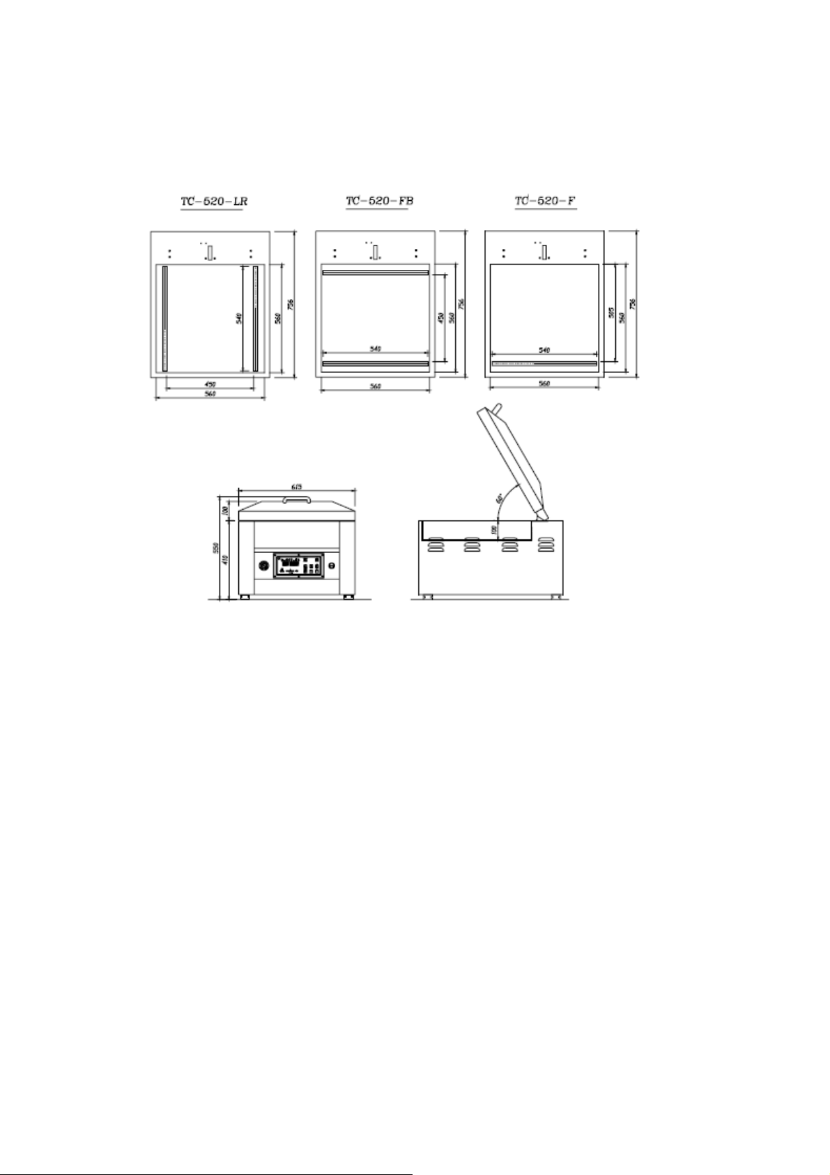
2.3 MACHINE
SPECIFICATI
ONS ..................................................................................... 5
2.4 ENVIRONMENT REQUIREMENTS .......................................................................... 5
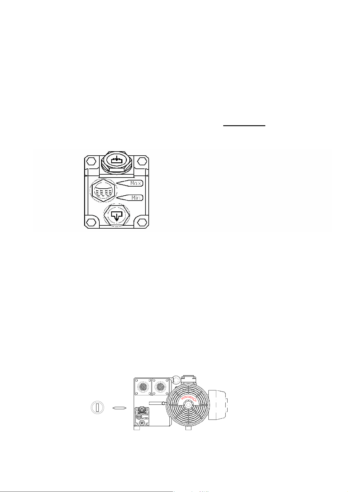
2.5 CHECK OIL LEVEL ..................................................................................................... 6
2.6 POWER CONNECTION ............................................................................................... 6
2.7 VACUUM PUMPROTATION ...................................................................................... 6
3. OPERATION........................................................................................................... 7
3.1 VACUUM SETTING GUIDELINES ............................................................................ 7
3.2 BASIC OPERATING INSTRUCTIONS ...................................................................... 7
3.3 OPTIONALDEVICE ..................................................................................................... 7
3.3.1 GAS FLUSHING UNIT ....................................................................................... 7
3.4 OPERATION OF THE PA-01 ANALOG CONTROL PANEL .................................. 8
3.5 OPERATION OF THE PD-01 DIGITALCONTROLPANEL .................................. 9
4. MAINTENANCE .................................................................................................... 9
4.1 BASIC MAINTENANCE ............................................................................................. 9
4.1.1 DAILYVISUAL INSPECTION ......................................................................... 9
4.1.2 DAILY CLEANING ............................................................................................. 10
4.2 VACUUM PUMPMAINTENANCE ............................................................................. 10
4.3 SEALBAR MAINTENANCE ....................................................................................... 10-11
4.4 MAINTENANCE INTERVALCHART ....................................................................... 12
5. TROUBLESHOOTING ........................................................................................ 13
5.1 PROBLEMS AND CORRECTIONS ............................................................................ 13-14
6. DRAWINGS ........................................................................................................... 15
6.1 PNEUMATIC DIAGRAM(F) ........................................................................................ 15
6.2 PNEUMATIC DIAGRAM(LR) ..................................................................................... 16
6.3 ELECTRICAL DIAGRAM ........................................................................................... 17
7. FABRICATION ..................................................................................................... 18
7.1 BODY DIAGRAM ........................................................................................................ 19-20
7.2 VACUUM CHAMBER DIAGRAMS ............................................................................ 21
7.2.1 VACUUM CHAMBER DIAGRAM(F) .............................................................. 21-23
7.2.2 VACUUM CHAMBER DIAGRAM(LR) .......................................................... 24-26
7.3 SEALING BAR CONFIGUATIONS ............................................................................ 27
7.3.1 SEAL BAR DIAGRAM(F) .................................................................................. 27-28
7.3.2 SEAL BAR DIAGRAM(FC) ............................................................................... 29-30
7.4 LID DIAGRAMS ............................................................................................................ 31
7.4.1 LID DIAGRAM(F) ............................................................................................... 31-32
7.4.2 LID DIAGRAM(LR) ........................................................................................... 33-34
7.4.3 LID DIAGRAM(TB) ............................................................................................ 35-36

7.4.4 SEAL BAR DIAGRAM (TB) .............................................................................. 37-38
7.5 ELECTRICAL BOX ....................................................................................................... 39
Explanation of Abbreviations
(F) Front Seal
(LR) Left & Right Seal
(FC) Front Seal with Hot Wire Cut-off
(LRC) Left & Right Seal with Hot Wire Cut-off

General
This owner’s manual contains information relating to your Promax/ Promarks machine. It will provide
you with basic information concerning both operation and maintenance of your new machine. Please
read it carefully as failure to do so may result in bodily injury and / or damage to the equipment.
Please fill in the information below. You will find the information on the bill of lading and on the
machines identification tag. You will need this information when ordering replacement parts or
making technical inquiries.
Model # _____________________________
Serial # ______________________________
Ship Date: ____________________________
Owner: _______________________________
Location: _____________________________

1
1.SAFETY
1.1SAFETY RECOMENDATIONS
Unsafe practices or unauthorized modifications of machine could result in accidents or property
damage.
For safe installation, operation, handling and maintenance, please strictly follow the simple safety
rules stated below and take precautions. Failure to follow these safety rules and take necessary
precautions can result in serious injury or death as well as cause damage to the equipment.
1) Never operate or service your Promax / Promarks machine until you have read this manual
completely and understand it fully.
2) All adjustments and repairs must be carried out only by qualified technicians or maintenance
personnel.
3) No service work should be attempted until the machine’s power has been turned off.
All proper lock out / tag out procedures should be followed.
4) Do not put tools, parts or other foreign objects on or into the machine.
5) Always keep the machine clean, lubricated and in good working condition.
6) To provide protection against the risk of electrical shock the power connection must be
properly grounded at all times.
7) The machine should always be operated on a flat stable surface.
8) A certified electrician should be employed to install the permanent electrical
connections for your new machine.

2
1.2PERSONALSAFETY
Please read and understand this operation manual before using this equipment. Failure to
follow the operating instructions may result in personal injury or damage to the machine.
The following procedures and guidelines must be observed to avoid problems that can result in
property damage, personal injury or death. If you have any questions regarding this information
please contact Promax /Promarks, Inc. Service Department at (909) 481-3338.
Hazardous Voltage:DANGER
Electrical power must be disconnected and locked out before servicing or cleaning of the machine.
Do not remove any panels before power has been disconnected and locked out due to the risk of
electric shock hazard.
Explosion Hazard: DANGER
When utilizing the gas flush feature (optional) do not use any gas mixture with greater than 22%
oxygen content.
Blade Hazard: WARNING
If your machine is equipped with either a Perforating Knife System (optional) or a Precut Knife
System (optional) then do not remove or install blades without wearing protective gloves. These
blades are SHARP, use care when handling.
Signal words used in classifying potential hazards are defined as follows:
DANGER: Indicates an imminently hazardous situation, which if not avoided, may result
in death or serious injury.
WARNING: Indicates a potentially hazardous situation, which if not avoided, could result
in serious injury.
CAUTION: Indicates a potentially hazardous situation, which, if not avoided, may result
in minor to moderate injury. Caution also indicates actions that may cause property
damage.

3
1.3FOOD SAFETY
While many Promax / Promarks machines are used in applications involving vacuum packaging
and vacuum cooking, there are inherent risks associated with these techniques that can result in
serious illness or death to the consumer of the food product. Therefore if you are using
your machine for food applications, you must consult a qualified food technician or specialist
in vacuum / modified atmosphere (M.A.P.) to review the safety of your application.
GAS FLUSH
If your machine is equipped with gas flush (optional) and your application involves the use of
gas flush to extend the shelf life of your product you must consult a qualified food technician or
specialist to review your application and develop a suitable gas mixture for your package.
Further you must perform quality control and gas analysis on your final M.A.P. package.
CLEANING
Every environment and application is different; therefore Promax / Promarks cannot provide
cleaning procedure instructions that will guarantee microbiological sanitation. Therefore Promax /
Promarks recommends that the purchaser of these machines consult with a sanitation expert to
review your procedures for cleaning the machine while operating in your environment and with
your specific product to develop a robust cleaning schedule and methodology,followed by
bacterial testing to ensure satisfactory cleaning is achieved.

4
2.INSTALLATION
2.1
UNPACKING
Carefully remove the cardboard outer shell by cutting the retaining straps then removing
the top and then the side panels.
Inspect the machine carefully for any hidden shipping damage. Notify the shipping
company right away if any damage is observed.
Remove the machine from the wooden skid. This can be done by two people on the
smaller table top machines. However an approved fork lift will be required for the larger
SC and DC models. Important note: Refer to the Moving the Machine Section below.
Wipe down the outside of the machine.
2.2 MOVINGTHE MACHINE
Promax chamber style vacuum packaging machines are available in three basic designs, TC
(Table Top), SC (Free Standing Single Chamber) and DC (Double Chamber). Recommendations
for the movement of all three types are listed below.
TC Machines: Some of the smallest TC units may be lifted off of their wooden skid and moved
manually. However Promax recommends that moving even the smallest of their TC units
should not be attempted by one person. The larger TC units should be lifted with the aid of a
fork lift or other approved lifting aid. Prior to lifting with a forklift the forks should be adjusted to
a width that provides the machine with stable support. The proper lifting point for TC machines is
to place the
forks so they come in contact with the units rubber feet located on the bottom of the
machine.
SC Machines: All SC units should be lifted from their wooden skid and moved to the location
where they will be used with an approved fork lift. Be sure to take note of the points listed below.
DCMachines: All DC units should be lifted from their wooden skid and moved to the location
where they will be used with an approved fork lift. Be sure to take note of the points listed below.
* Make sure the fork lift forks are properly adjusted for width and use fork extensions if needed.
*Make sure to ascertain the center of gravity and use identified lifting points.

5
2.3 TC-520 SPECIFICATION
2.4ENVIRONMENT
EQUIREMENTS
The machine will be difficult to start ifthe air temperature is very low. This is caused by the
increase in the vacuum pump’s oil viscosity due to the low temperature. To prevent this, please set
up machine according to the installation checklist described as below:
zTemperature: around 5 ~ 40℃
zWorking elevation: between 0 ~ 1000 meters
zRelative humidity: 30 ~ 95% RH
zDuring operating, heat is generated by the vacuum pump and vacuum process, so a
machine temperature of around 70 ~ 80℃ is normal. The machine must have free air
access for cooling.
zA minimum distance from walls, other machines, etc. should be maintained, at least 20 cm for
each side of machine for providing adequate ventilation.

6
2.5CHECK OIL LEVEL
Check the oil level only when the machine is not in operation and all
vacuum built up in the chamber has been vented. Be aware that the oil
may be very hot and avoid all contact.
Checking the Oil Level
*
Check the oil level on a daily basis
*
When checking the oil level use the sight gauge shown in figure 1 below. The level
should be between the arrows indicating Minimum and Maximum. If the level is below the
minimum arrow add oil until the maximum arrow is reached.
Figure 1
2.6 POWERCONNECTION
When preparing to install the machine’s main power connection please refer to the electrical
information on the serial number plate located on the machine’s back panel. A certified
electrician should be employed to complete this connection.
2.7 VACUUM PUMP ROTATION
If your machine operates on 3 phase power it is important to check the rotation of the vacuum
pump. The pump should turn in the direction indicated in Figure 2 below. If the pump turns
in the wrong direction it will make a sound that is obviously wrong. Turn off the power
immediately and change the position of two of the power wires and retest.
Figure 2
Main switch

7
3. OPERATION
3.1 VACUUM SETTING GUILDLINES
Pr
odu
c
ts
Vacuum time/Sec. Storage life when stored
at
2~ 6
℃
/
day
Fresh meat
30
10
Pork
30
10
Bee
f
30
30
Meat with liquid 15~
30
14
P
a
s
ta 3~
9
21
Sliced sausage
15
10
Cold cut
s
9
10~
21
3.2BASIC OPERATING INSTRUCTIONS
Turn on the main switch and the LED display shows the operation menu, at this time, machine is
ready to operate.
Place the product to be packaged in a vacuum pouch. Place the bag in chamber with the open end
of bag across the sealing bar. (With a package that doesn’t completely fill the chamber, place
provided flat plates in the chamber to shorten vacuum time.)
Close the lid to start the cycle, the lid will open automaticallywhen cycle is completed.
Take out the sealed product from vacuum chamber.You are ready to start the next cycle.
After all packaging is completed, please let the vacuum pump run for about 15 minutes, then turn
off the main switch to shut down the machine.
3.3OPTIONAL DEVICE
3.3.1 GAS FLUSHING UNIT
If your machine is equipped with an optional gas flush system please note the following points.
Make sure you have connected a regulated gas source to the gas inlet fitting
Do not set your regulator for a pressure of greater than 40psi
Place the open end of your package in front of the gas inlet nozzles
Do not tuck the bag under the gas nozzles

8
3.4 Operation of the Model PA-01 Analog Control Panel
On the model PA-01 analog control panel you will see four (4) dials from left to right they are
vacuum, gas, seal and cool (Refer to Fig. 3 below). When setting these dials to accomplish your
intended cycle please keep in mind that the reference numbers around each dial are only to
be used as a reference as they do not equate to seconds.
Proceed with setting these dials as indicated below. The settings indicated will be for a trial cycle and
various settings of each dial may be needed to achieve the results you require.
Set Each of the Dials as Follow.
1. Vacuum: Turn the dial to # 5
2. Gas: (optional feature) If your machine is equipped with the gas flush option and you wish to
gasflushthepackageyouarecurrentlyworkingwithturnthisdialto#2.
If your machine does not have the gas flush option or you do not wish to gas flush then turn the
dial to # 0.
3. Seal: Turn the dial no higher than # 3 for your first trial then increase or decrease as needed for
your pouch.
4. Cool: Turn to a minimum of # 3

9
3.5 Operation of the Optional PD-01 Digital Control
Using the touch up/down touch pads (Refer to Fig. 4 below) set the time for the vacuum, gas
, and seal and cool as indicated below. The times indicated in the digital display are in seconds.
Important note: the settings indicated below represent a starting point only and you will need to
perform adequate testing to determine the exact settings needed for your product.
1.Vacuum: Set a time of 15 seconds
2.Gas Flush (optional): If your machine is equipped with a gas flush system set a time of 5 seconds. If
your machine does not have a gas flush system or you will not use gas flush for the current application
then it is very important to set a time of 0.0 seconds.
3.Seal: Set a time of 1.5 seconds.
4.Cool: Set a time of 3.0 seconds.
4. MAINTENANCE
4.1 Basic Maintenance
The following maintenance procedures should be followed no matter what model Promax machine
you own.
4.1.1 Daily Visual Inspection
Your machine should have the following items inspected daily. If this inspection is performed daily
prior to the start of your days production you will find that your machine will always perform
consistently, last longer and suffer less down time.
A. Teflon Covers
1. Clean if they have any foreign mater adhering to them
2. Look for any burned spots, cuts or tears. Replace if needed.
B. Vacuum Pump Oil
1. Check the oil level. Fill if below Minimum on the sight gauge. Refer to Page 7.
2 . Replace the oil after 500 hours of operating time.
C. Vacuum Chamber Lid Gasket
1. Check for general wear
2. Check for damage
3. Replace as needed.

10
D. Pressure Bar Rubber:On TC and some SC machines this is the rubber part found in the lid of
your machine that meets with the seal bar when the machine is in operation. In other SC machines and
in all DC machines this is the rubber part that is located on the chamber’s base that meets with the seal
bar when the machine is in operation.
1 Check for excessive wear.
2. Check for burnt spots, cuts and tears.
3. Replace as needed.
E. Vacuum Pump Motor Sound
1. Listen for the smooth, normal sound of your vacuum pump.
2. If any abnormal sounds are detected TURN OFF YOUR MACHINE RIGHT AWAY and
perform a trouble shooting procedure..
4.1.2 Daily Cleaning
Important Note: The following daily cleaning points are meant to help keep your machine in proper
working order. They are in no way intended to provide the required level of sanitation needed for the
packaging of food products. As noted earlier in this manual your company should consult with an expert in
the sanitation field to design a robust sanitation routine when packaging food products.
1. Clean the seal bar’s Teflon tape very carefully using a rag and a mild organic solvent. DO NOT
directly wash down this area of the machine.
2. Clean the rubber pad in the seal pressure bar. Once again use a rag and a mild organic solvent. DO
NOT directly wash down this area of the machine.
3. Wipe down the stainless steel housing using an approved stainless steel cleaner.
4. On machines with clear chamber lids or viewing windows clean them using a mild glass cleaner.
5. If your machine is an SC Series or a DC Series unit open the housing access door and visually
check for oil or debris around the vacuum pump area. If you see anything that needs to be cleaned
DO NOT start cleaning until the machine is properly locked out and tagged out.
4.2 Vacuum Pump Maintenance
For detailed information concerning maintenance and repair of your machine’s vacuum pump please
refer to the manufactures operating manual that was packaged with your new machine.
4.3 Seal Bar Maintenance
A. Replacing the Teflon Cover
1. Remove the seal bars from your machine.
a. Seal bars are located in the chamber on all TC Series machines and some smaller SC Series
machines.

11
ٛb. Seal bars are located in the lid on larger SC Series machines and all DC Series machines.
2. Remove the screws that hold the Teflon holding strap in place. Refer to Figure A on the next
page.
3. Remove the old Teflon cover.
4. Inspect the seal element.
ٛa. Clean it off with lacquer thinner if needed.
ٛb. Replace if broken or burnt badly. Refer to the instructions under B below for replacement
5.Install the new Teflon cover and reinstall the seal bars.
B. Replacing the Seal Element
1. Using a hex wrench loosen the screws holding the seal element and remove it
2. Install the new seal element. Refer to Figures B & C on the next page.
a. Place the new element across the surface of the seal bar leave an excess of about 3/4” at
each end.
b. Make sure you put the tension spring back in place..

12
4.4 MAINTENANCE INTERVALS AND CHECK ITEMS
Maintenance Intervals/
Check items
Daily
Bimonthly
Quarterly
Yearly
Biyearly
3 ~ 5 years
Note
Keep the vacuum lid
open after finished
working and let
vacuum pump running
about 15 minutes.
X
Check the oil level X
Check the sound of
motor
X
Oil come out from
exhaust cover or not
X
Bottom sealing bar
working normally or
not
X
Clean the exhaust filter X
Change vacuum oil X
Replace exhaust filter X
Replace Teflon tape XAs request
Replace sealing
Silicone rubber XAs request
Replace lid gasket
rubber XAs request
Replace pressure bag XAs request
Replace vanes X
Above-mentioned maintenance intervals are scheduled basically for 8 working hours per day.
Recommended oil : A. Grav. API 30.5
Pour Pt. -15℃
Flash Pt. 225℃
Viscosity 32.05 CST@40℃
Color Light Yellow
V.I. 100

13
5. TROUBLESHOOTING
5.1 Problems and Corrections
Problem and Corrections - Review installation procedure section to ensure the installation is correct. If
correct, the troubleshooting chart below lists possible problems, causes, corrections, and reference guide.
Problem Cause Correction
Control panel is under normal
function, but vacuum pump
does not start.
The KM1, QM1, MCB1,
MCB2 protectors are
disconnected.
Check each part and turn on the
switch, reconnect, if necessary.
Vacuum pump does not run. The power supply is not
corresponding with the power
demand indicated on the back
of machine.
Reconnect to correct power
source.
Insufficient vacuum in
chamber. Low oil level in vacuum pump.
Vacuum pump is rotating in
wrong direction. Lid silicone
rubber damaged.
Fill oil, if necessary. Stop
machine immediately. Then
alter the power connection and
reconnect to correct ones.
Replace.
Insufficient vacuum in bag.
Note : Mostly insufficient
vacuum in bag is due to leakage
of bag, but not the fault of
machine.
Bag is leaking. Sharp corners
on wrapped product puncture
the bag. Bag is too large.
Replace the bag. Replace the
bag and use a thicker one.
Replace with a smaller one.
Vacuum bag is easily pulled
apart by hand. Sealing time (temperature) is
too short (low). Adjust sealing time
(temperature) to be longer
(higher).
Sealing area has some burnt
marks or bubbles appeared. Sealing area stuffed with oil or
meat juice or dirt. Sealing time
(temperature) is too long (high).
Clean and remove them. Adjust
sealing time (temperature) to be
shorter (lower).
Lid does not open. Vacuum valve is damaged. Replace it.

14
Problem Cause Correction
No or improper sealing.
NOTE : Please do not adjust
sealing longer than regular time,
or it will reduce the life of
Teflon tape and silicone rubber.
Insufficient pressure. Sealing
transformer is damaged. Teflon
tape or silicone rubber is
damaged. Sealing time and
cooling time are too short.
Sealing pressure is too low.
Heating element is loose.
Heating element is broken.
Replace it. Tighten it. Pressure
bar is damaged, replace it.
Replace it. Replace it. Adjust to
proper time. Replace the
pressure bag.
Lid does not close. Vacuum valve is damaged.
Limit switch is disconnected or
damaged.
Replace it. Reconnect or
replace it.

15
6 DRAWINGS
6.1 PNEUMATIC DIAGRAM (F)

16
6.2 PNEUMATIC DIAGRAM (LR)
Table of contents
Other Omcan Kitchen Appliance manuals

Omcan
Omcan MS-CN-0170 User manual

Omcan
Omcan PE-CN-1800-S User manual

Omcan
Omcan CE-CN-0012-E User manual

Omcan
Omcan VP-IT-0300 User manual

Omcan
Omcan MS-IT-0250-M User manual

Omcan
Omcan MS-IT-0350-H User manual

Omcan
Omcan MS-IT-0370-H User manual

Omcan
Omcan MS-IT-0370-H User manual

Omcan
Omcan VP-NL-3016-SN User manual

Omcan
Omcan MS-IT-0330-N User manual

Omcan
Omcan 28 User manual

Omcan
Omcan TS-7000 Configuration guide

Omcan
Omcan VP-IT-0330-S User manual

Omcan
Omcan MS-IT-0220-B User manual

Omcan
Omcan MS-CN-0195 User manual

Omcan
Omcan GR-CN-0559 User manual

Omcan
Omcan Volano MS-IT-0250-MF User manual

Omcan
Omcan WC-CN-0181-DB User manual

Omcan
Omcan FTS8 User manual

Omcan
Omcan SB-CN-0025 User manual