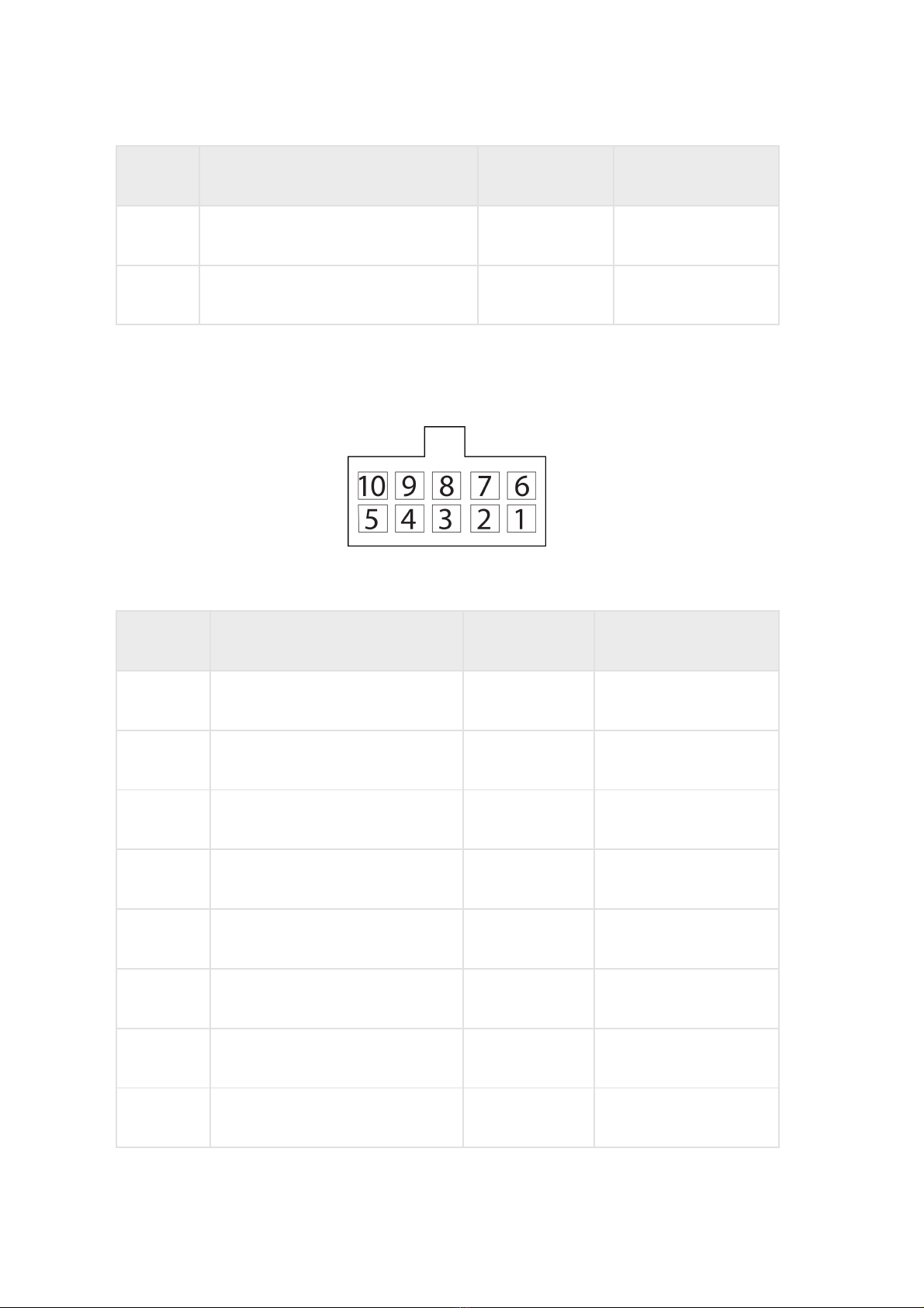
5 Universal input 4 Input 4 Black-yellow
6 RPM input Tachometer Blue
7 Controlled output 2 Output 2 Yellow-dark blue
8 Line RX RS-232 RS-232 RX Pink
9 Line B RS-485 №2 B RS-485 №2 Black-blue
10 Line B RS-485 №1 B RS-485 №1 Blue-white
11 CAN L CAN L Purple-white
12 Vehicle power supply voltage Power (positive) Red
13 Ignition key IGN Yellow
14 GSM Activation Button GSM Green-black
15 Universal input 1 Input 1 Black
16 Universal input 3 Input 3 Black-red
17 iButton+ iButton+ Pink-red
18 Controlled output 1 Output 1 Yellow-red
19 Line TX RS-232 RS-232 TX Grey
20 Line A RS-485 №2 A RS-485 №2 White-green
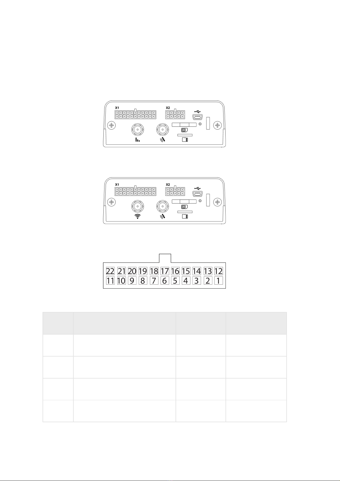
No. of pin Signal name Designation Wire colour in cable


