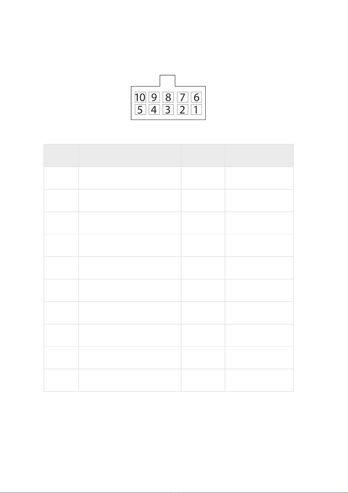
5 Universal input 2 Input 2 Black-white
6 Panic button Panic button White-red
7 Line B RS-485 LLS B RS-485 White-blue
8 CAN L CAN L Purple-white
9 Speaker - Speaker - Grey-yellow
10 Microphone - Microphone - Green-yellow
11 Vehicle power supply voltage Power Red
12 Ground for power – Ground (signal) White
13 RPM input Tachometer Blue
14 Ignition key IGN Yellow
15 Universal input 1 Input 1 Black
16 GSM activation button GSM Green-black
17 Line A RS-485 LLS A RS-485 Orange-white
18 CAN Н CAN Н Purple-orange
19 Speaker + Speaker + Grey-red
20 Microphone + Microphone + Green-red
No. of pin Nameof signal Designation Wire color in cable


