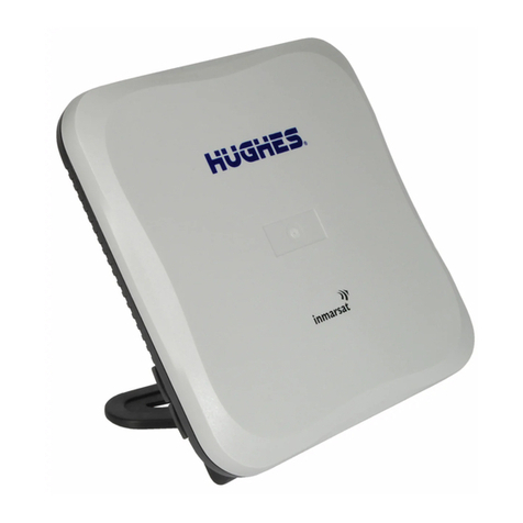
Hughes EchoStar Mobile 4500 User manual

Hughes 4500
User Guide
H62751
Revision C
July 12, 2021

2
Copyright and Trademark Statements
H62751 Revision C
Copyright © 2021 Hughes Network Systems, LLC
All rights reserved. This publication and its contents are proprietary to Hughes Network Systems,
LLC. No part of this publication may be reproduced in any form or by any means without the
written permission of Hughes Network Systems, LLC, 11717 Exploration Lane, Germantown,
Maryland 20876.
Hughes Network Systems, LLC has made every effort to ensure the correctness and completeness
of the material in this document. Hughes Network Systems, LLC shall not be liable for errors
contained herein. The information in this document is subject to change without notice. Hughes
Network Systems, LLC makes no warranty of any kind with regard to this material, including, but
not limited to, the implied warranties of merchantability and fitness for a particular purpose.
Trademarks
HUGHES, HughesNet, HughesON, IPoS, SPACEWAY, and JUPITER are trademarks of Hughes
Network Systems, LLC. All other trademarks are the property of their respective owners.

Contents
H62751 Revision C
3
Contents
Understanding safety alert messages....................................................................................... 5
Messages concerning personal injury .................................................................................................... 5
Messages concerning property damage ................................................................................................ 5
Safety symbols........................................................................................................................................ 5
Additional symbols........................................................................................................................... 5
Warnings for satellite terminal............................................................................................................... 6
Equipment users..................................................................................................................................... 7
Chapter 1
Introduction .............................................................................................................................. 9
1.1 Overview....................................................................................................................................... 9
1.2 About this user guide.................................................................................................................... 9
1.3 Package contents.......................................................................................................................... 9
1.4 Minimum system requirements for laptop/PC .......................................................................... 10
1.4.1 System requirements to support maintenance port ...................................................... 10
1.4.2 Additional hardware ....................................................................................................... 10
Chapter 2
Using the Hughes 4500 ........................................................................................................... 12
2.1 Before getting started ................................................................................................................12
2.2 Quick start...................................................................................................................................12
2.3 Connecting the terminal to the computer .................................................................................12
2.3.1 Connecting by Ethernet...................................................................................................12
2.3.2 Connecting by USB ..........................................................................................................12
Chapter 3
Using the Web UI .................................................................................................................... 13
3.1 Accessing the Web UI .................................................................................................................13
3.2 Home page.................................................................................................................................. 13
3.3 Connections ................................................................................................................................ 14
3.3.1 Manage connections.......................................................................................................
14
3.3.2 APN Profiles.....................................................................................................................15
3.3.3 Connection Profiles ......................................................................................................... 16
3.4 Settings page .............................................................................................................................. 18
3.4.1 General setup.................................................................................................................. 18
3.4.2 IP address/DHCP settings................................................................................................19
3.4.3 Ethernet security............................................................................................................. 20
3.4.4 Security............................................................................................................................ 21
3.4.5 Outbound filters.............................................................................................................. 23
3.4.6 Port forwarding ...............................................................................................................24
3.4.7 Remote management ..................................................................................................... 26
3.5 Usage statistics ...........................................................................................................................28
3.6 Support page .............................................................................................................................. 28
3.6.1 Information ..................................................................................................................... 28
3.6.2 Troubleshooting ..............................................................................................................29
3.6.3 Satellite Diagnostics ........................................................................................................ 31
3.6.4 Update Software .............................................................................................................32

4
Contents
H62751 Revision C
3.6.5 Restore Factory Defaults Procedure ...............................................................................33
Chapter 4
Troubleshooting ...................................................................................................................... 35
Chapter 5
Technical specifications .......................................................................................................... 37
Acronyms................................................................................................................................. 39

Understanding safety alert messages
H62751 Revision C
5
Understanding safety alert messages
Safety alert messages call attention to potential safety hazards and tell you how to avoid them. These
messages are identified by the signal words DANGER, WARNING, CAUTION, or NOTICE, as illustrated
below. To avoid possible property damage, personal injury, or in some cases possible death, read and
comply with all safety alert messages.
Messages concerning personal injury
The signal words DANGER, WARNING, and CAUTION indicate hazards that could result in personal injury
or in some cases death, as explained below. Each of these signal words indicates the severity of the
potential hazard.
CAUTION indicates a potentially hazardous situation which, if not avoided,
could result in minor or moderate injury.
Messages concerning property damage
A NOTICE concerns property damage only.
NOTICE is used for advisory messages concerning possible property
damage, product damage or malfunction, data loss, or other unwanted
results
—but not personal injury.
Safety symbols
The generic safety alert symbol calls attention to a potential personal injury hazard. It appears
next to the DANGER, WARNING, and CAUTION signal words as part of the signal word label. Other
symbols may appear next to DANGER, WARNING, or CAUTION to indicate a specific type of hazard (for
example, fire or electric shock). If other hazard symbols are used in this document, they are identified in
this section.
Additional symbols
This document uses the following hazard symbols:
Indicates a safety message that concerns a potential
electric shock hazard.
Indicates a safety message that concerns potential for
personal injury.

6
Understanding safety alert messages
H62751 Revision C
Indicates a safety message that concerns radio frequency
(RF) energy.
Warnings for satellite terminal
Do Not Stand near by the Antenna: This device emits radio
frequency energy. To avoid injury, do not place head or
other body parts in front of the satellite antenna when
system is operational. Maintain half meter distance or more
from the terminal while active is the warning.
General: Handle your Satellite Terminal with care. The unit
is weather resistant per IEC 60529 IP67; however, do not
submerge the unit. Avoid exposing your Satellite Terminal
to extreme hot or cold temperatures outside the
range -25° C to +65° C.
Avoid placing the Terminal close to cigarettes, open flames
or any source of heat.
Changes or modifications to the Terminal not expressly
approved by Hughes Network Systems could void your
authority to operate this equipment.
Only use a soft damp cloth to clean the Terminal.
To avoid impaired Terminal performance, please ensure the
unit’s antenna is not damaged or covered with foreign
material like paint or labeling.
When inserting the SIM, do not bend it or damage the
contacts in any way. When connecting the interface cables,
do not use excessive force.
In the Vicinity of Blasting Work and in Explosive
Environments:
Never use the Satellite Terminal where blasting work is in
progress. Observe all restrictions and follow any regulations
or rules. Areas with a potentially explosive environment are
often, but not always, clearly marked. Do not use the
Terminal while at a petrol filling station. Do not use near
fuel or chemicals.
Qualified Service: Do not attempt to disassemble your
Satellite Terminal. The unit does not contain consumer-
serviceable components. Only qualified service personnel
may install or repair equipment.

Understanding safety alert messages
H62751 Revision C
7
Accessories: Use Hughes approved accessories only. Use of
non-approved accessories may result in loss of
performance, damage to the Satellite Terminal, fire, electric
shock or injury.
Connecting Devices: Never connect incompatible devices to
the Satellite Terminal. When connecting the Satellite
Terminal to any other device, read the device’s User
Manual for detailed safety instructions.
Pacemakers: The various brands and models of cardiac
pacemakers available exhibit a wide range of immunity
levels to radio signals. Therefore, people who wear a
cardiac pacemaker and who want to use a Satellite
Terminal should seek the advice of their cardiologist. If, as a
pacemaker user, you are still concerned about interaction
with the Satellite Terminal, we suggest you follow these
guidelines:
Maintain a distance of half meter from the main antenna
front and sides and your pacemaker
Refer to your pacemaker product literature for information
on your particular device
If you have any reason to suspect that interference is taking
place, turn off your Satellite Terminal immediately.
Hearing Aids: Most new models of hearing aids are
immune to radio frequency interference from Satellite
Terminals that are more than 2 meters away. Many types
of older hearing aids may be susceptible to interference,
making it very difficult to use them near a Terminal. Should
interference be experienced, maintain additional
separation between you and the Satellite Terminal.
Electrical Storms: Operation of the Satellite Terminal during
electrical storms may result in severe personal injury or
death.
Equipment users
User must be a skilled person. Designated users should not be exposed to conditions that could cause
pain or injury, nor intentionally cause said conditions.

8
Understanding safety alert messages
H62751 Revision C

Chapter 1 • Introduction
H62751 Revision C
9
Chapter 1
Introduction
1.1 Overview
The Hughes 4500 Terminal provides reliable satellite connectivity over the EchoStar® Mobile GMR-1 3G
satellite network. The Hughes 4500 Terminal comes in a very small form factor and allows the user to
send and receive IP packets via Ethernet.
Figure 1: Hughes 4500 Terminal
1.2 About this user guide
This user guide contains the most up-to-date information available on this product on the date it was
generated. It focuses on the specific information required to operate the Hughes 4500 Terminal and
connect to the EchoStar Mobile™ satellite network. If you are a first-time user, you will be guided
through the procedure for powering up your terminal, obtaining a GPS fix, connecting your computer to
the terminal, and registering with the network. After you have completed these steps, you are ready to
start using the data services.
1.3 Package contents
When you unpack the Hughes 4500 Portable Terminal kit package, you will find the following:
•Hughes 4500 Terminal
•Quick Start User Guide
Your service provider will supply you with a UMTS Subscriber Identification Module (USIM), its PIN, and
satellite terminal configuration instructions. You will need these to access the satellite network.

10
Chapter 1 • Introduction
H62751 Revision C
1.4 Minimum system requirements for laptop/PC
These are the minimum computer system requirements for successful interface with the satellite
terminal:
•Internet browser: Microsoft Internet Explorer (IE11 or later), Mozilla Firefox, Chrome, or Safari
•PC support for Ethernet
•PC support for USB
1.4.1
System requirements to support maintenance port
To support the maintenance port, intended as the USB port, the following Operating Systems (OSs) have
been tested, and they do not require the installation of any USB drivers:
•Microsoft Windows 7
•Microsoft Windows 10
1.4.2
Additional hardware
Please refer to the Hughes catalog and pricelist to purchase any optional additional hardware items.
Table 1: Additional hardware items from the Hughes catalog
Item
Part Number
Specifications
Fixed Mounting Bracket
3501366-0001
High-quality, corrosion-resistant
angle bracket for mounting the
terminal to a vertical, flat surface.
Pole mounting can be accomplished
by adding U‑clamps, which can be
sourced separately.
Magnetic Mounting Kit
3501365-0001
Custom-designed kit for mounting
the terminal to a horizontal,
magnetic, flat surface.
The kit contains all the parts needed
to add magnetic mounting to the
terminal.
Pole Mount Kit
POLE-MOUNT-KIT
Pole mount, U-bolts (2), and a fixed
mount bracket for a convenient pole
mount install.
Power and Data Cable, Blunt Wire (5 m)
3501314-0002
Ready-made cables for connecting
the terminal to DC power and
Ethernet data.
Power and Data Cable, Blunt Wire (10 m)
3501314-0003
Ready-made cables for connecting
the terminal to DC power and
Ethernet data.
Power and Data Cable, Cigarette Lighter
Plug, and RJ45 Socket (5 m)
3501314-0004
The cigarette lighter plug and RJ45
version are ideal for temporary
vehicular installs.
RJ45 Wiring Block
9510250-0002
The RJ45 wiring block is useful with
blunt wire cables.

Chapter 1 • Introduction
H62751 Revision C
11
Item
Part Number
Specifications
Mating Power and Data Connector (bare)
9509554-0001
Custom Power and Data Cable, 8.5 mm
OD (100 m)
9509897-0001 The bulk cable and solder-ready
barrel connector allow for custom
cable installations.

12
Chapter 1 • Using the Hughes 4500
H62751 Revision C
Chapter 2
Using the Hughes 4500
2.1 Before getting started
Install the USIM into the terminal unit before powering up the unit.
Figure 2: Inserting the USIM card
2.2 Quick start
The Hughes 4500 Terminal must first obtain a GPS fix. In order to do this, the terminal must be
positioned with an open view of the sky. The GPS fix is acquired by the time the terminal is fully booted
up. This time is typically specified at 30 seconds.
2.3 Connecting the terminal to the computer
You can connect your computer to the Hughes 4500 with one or more of the following interfaces:
•Ethernet
•Micro USB
2.3.1
Connecting by Ethernet
To connect the Hughes 4500 Terminal to a device using Ethernet:
•Connect a standard Ethernet cable to the Ethernet signals of the barrel connector.
2.3.2
Connecting by USB
The common installation access port for installers is the Micro-USB port. To connect the Hughes 4500
Terminal to a device using USB:
•Connect a standard micro USB cable to the micro USB signals of the barrel connector.
The USB port can be only used for configuration. It cannot be used for
user data connections over the satellite link
.
USB port
LED
USIM port
Factory Defaults
button

Chapter 3 • Using the Web UI
H62751 Revision C
13
Chapter 3
Using the Web UI
3.1 Accessing the Web UI
The Hughes 4500 includes an internal Web User Interface (Web UI). To access the Web UI, open your
preferred web browser and enter the internal IP address of the terminal.
•If you are using an Ethernet port, enter this Ethernet IP address:
–http://192.168.128.100
•If you are using a USB port, enter this maintenance IP address:
–http://169.254.1.1
The Web UI opens up to the Terminal Status page. Along the top of all Web UI pages are icons
representing the categories of available subpages: Home, Connections, Settings, Usage, and Support.
3.2 Home page
The Home page shows the current terminal status and allows user to set up the initial data connection.
On the left side of the page is the Status bar. These items are updated automatically when the status of
any item changes.
1. Connection: This field indicates whether you are registered with the EML Network. It also shows
the receive signal strength and if you are registered with the IMS.
2. Position: This field displays the current position status. If the terminal acquired a GPS fix, it will
display the latitude, longitude, altitude, the last time the GPS position was updated and the
geocoordinates in the Military Grid Reference System (MGRS). The time is displayed in UTC.
3. Terminal Properties: This field indicates miscellaneous status information.

14
Chapter 3 • Using the Web UI
H62751 Revision C
Figure 3: Terminal Status page
Once connected to the network, the Terminal Status page will show that the UT is registered with the
network. In the middle of the Terminal Status page, it will show that the Shared Connection is
established along with the Terminal Equipment’s (TE) local IP address.
For basic connectivity, the terminal would function with one signal bar. For more details, the user can
reference the Diagnostics page to see if the Signal Quality Index (SQI) is at least 5 dB. It is desirable to
have 10 dB or better.
3.3 Connections
The Connections page allows the user to manage the data connections. The following are the available
subpages:
•Manage Connections
•APN Profiles
•Connection Profiles
3.3.1
Manage connections
This page allows the user to manage the satellite connections:
•Shared Connection: This section displays the connection status, global IP, and an action button
to disconnect or connect. The shared connection is automatically established when the terminal
powers up.
•Local Devices Using the Satellite Shared Connection: This section displays the local IP addresses
of all devices connected to the satellite shared connection (port translation NAT).
•Dedicated Connection 1 and Dedicated Connection 2: This section displays the status of the
custom dedicated connections, the local IP, the APN profile, the global IP, and an action button
to disconnect or connect. The dedicated connection is specific to the TE, which is configured to
use the connection. This makes the TE directly addressable from the Global Networking Space

Chapter 3 • Using the Web UI
H62751 Revision C
15
(basic NAT). After a TE establishes a dedicated data connection, it no longer uses the shared
connection.
To establish a connection with the network, select one of the profiles from the APN Profile dropdown
menu and click the Connect button. Once connected, the global IP field will be populated, and the
Connect button will change to Disconnect.
Figure 4: Connection page
3.3.2
APN Profiles
•Profile Settings: This section allows the user to choose the default satellite APN profile by
selecting the APN profile from the dropdown menu and clicking the Apply Changes button. At
least one profile needs to be configured and selected as the default profile.
•Defined APN Profiles: This section allows the user to configure up to five APN profiles for use
with satellite or cellular connections. Enter values for the following fields to define a new
APN profile:
–Profile Label
–Profile APN
–APN Username
–APN Password
Note: The APN Username and APN Password fields are mandatory.
After clicking Apply Changes, an APN profile will be created and will appear on the APN profile table.
The profile can be configured to prompt for a password when selected.

16
Chapter 3 • Using the Web UI
H62751 Revision C
Figure 5: APN Profiles page
3.3.3
Connection Profiles
This page allows the user to configure the user data connections (shared and dedicated) by selecting an
APN profile and an activation method.
•Connection Watchdog: This section allows the user to enable the Connection Watchdog feature
in order to monitor the traffic. The user can also configure the following options:
–Traffic Monitoring:
•Do not monitor
•Monitor only incoming
•Monitor only outcoming
•Monitor bi-directional
–Traffic Period: This is the period of the traffic monitoring feature. This value should be set
based on the expected data usage of the terminal. The default duration is 10 minutes.
–Always Send Pings: This feature allows the UT to send pings, even when the traffic flow is
detected.
–Ping Servers: This displays the IP addresses of servers to be used when verifying link
connectivity.

Chapter 3 • Using the Web UI
H62751 Revision C
17
•Connection Profile – Shared Connection: This section allows the user to define the APN profile
of the shared connection and how the shared connection is established. The user can select the
options available from each of the dropdown menus and confirm them by clicking Save.
•Connection Profile – Dedicated Connection 1 and Dedicated Connection 2: This section allows
for automatic activation of a dedicated satellite connection. The user can enable a dedicated
connection by checking the Enable box. The user can also configure the activation as noted
below:
Figure 6: Connection Profiles page
–Activation Method:
•Manually: The user manually connects and disconnects the connection on the Web UI.
•Always-On: The connection is automatically established after attaching to the network,
and it will automatically re‑establish when dropped unexpectedly.
•Automatic Context Activation (ACA): The connection is automatically established when
eligible devices are detected. This refers to a connected device that matches the local IP
address criteria to activate the automatic context.
The user must select the local IP address for the connection and select the APN profile and activation
method using options available from the dropdown menus. Clicking the Save button confirms the
changes.
Note: The dedicated connection profile must be enabled to take effect. When a dedicated connection is
configured for manual activation, the connection profile settings will be used as hard-coded
defaults on the Manage Connections screen. This allows a user with the administration password
to lock the settings that can be used when activating dedicated connections.

18
Chapter 3 • Using the Web UI
H62751 Revision C
3.4 Settings page
The Settings page provides a set of subpages for the configuration of the following various terminal
parameters:
•General Setup
•IP Address/DHCP
•Ethernet Security
•Security
•APN Profiles
•Connection Profiles
•Outbound Filters
•Port Forwarding
•Remote Management
3.4.1
General setup
This subpage allows the user to configure general parameters of the Hughes 4500 Terminal. A
description of each item is as follows:
•Language: The user can choose between the different language options by selecting a language
from the dropdown menu and clicking the Apply Changes button.
•LED Settings:The user can select between three different display options for the LED indicators
in normal operating mode. After selecting a new display option from the dropdown menu, the
user can confirm the setting by clicking Apply Changes.
The LED states in normal operating mode are explained in Table 2:
Table 2: LED states in normal operating mode
State
LED
Powering up
Solid GREEN
Network acquisition
Flashing GREEN
Registered and IP context active
Solid GREEN
Hardware fault
Solid RED

Chapter 3 • Using the Web UI
H62751 Revision C
19
Figure 7: Settings page
3.4.2
IP address/ DHCP settings
•Terminal Local IP Address: This section allows the user to change the local IP address of the
terminal from the default Ethernet IP address: 192.168.128.100. All four octets are available
to change. Once the local IP address is changed on this page and applied, the first three octets of
the DHCP address range will also change automatically.
•DHCP Server: This allows the DHCP server in the UT to be turned on or off by checking the
Enable box.
•DHCP Address Range: This allows the user to set the range of DHCP addresses (from .101 to
.199) that are given out by the UT to connected TEs. Changing the DHCP address range requires
an immediate reboot. The following IP addresses are reserved by the UT:
–IP address of the terminal (e.g., 192.168.128.100)
–IP address just below (e.g., 192.168.128.099)
Note: When updating the DHCP address range, the following settings will be updated or
reset and may need to be revisited:
–DHCP Address Range
–DHCP Reservations
–Port Forwarding
–Port Triggering
–Outbound Filters
•DHCP Reservations: This section allows the user to add an IP address that will permanently be
assigned to a particular connected device based on the detected device’s MAC address.

20
Chapter 3 • Using the Web UI
H62751 Revision C
Figure 8: IP address/DHCP screen
3.4.3
Ethernet security
This page allows the user to enable Ethernet MAC Address Filtering:
•Ethernet MAC Address Filtering: User can select any detected device and add the MAC address
to the Allowed MAC Addresses field to the left. The user can also manually add a MAC address in
the box at the bottom of the page and then add it to the Allowed MAC Address field.
Other manuals for EchoStar Mobile 4500
2
Table of contents
Other Hughes Touch Terminal manuals

Hughes
Hughes DIRECWAY DW7000 User manual

Hughes
Hughes 9502 User manual

Hughes
Hughes HN7000S User manual

Hughes
Hughes EchoStar Mobile 4500 User manual

Hughes
Hughes 9202 User manual

Hughes
Hughes EchoStar Mobile 4500 User manual

Hughes
Hughes 9350 User manual

Hughes
Hughes HNS 9201 User manual

Hughes
Hughes HNS 9201 User manual

Hughes
Hughes 9201 User manual