Omron E3Z-LASER User manual

1E3Z Laser Models
Laser Photoelectric Sensor with Built-in Amplifier
E3Z-Laser
Compact
photoelectric sensor
with LASER light
The E3Z LASER sensor in compact
plastic housing features visible LASER
light for precision positioning and detec-
tion applications.
• Visible LASER light for precision posi-
tioning and small object detection
• High power LED for high functional
reserve
Features
Through-beam and Retroreflective Sensors
Greatly Enhanced Beam Visibility for Easier Optical Axis Ad-
justment of Sensors
• The optical design maximizes the linear propagation of la-
ser beams. Red laser beams (class 1) can be precisely
aligned on the targeted position.
• The functional reserve of the rated through-beam sensing
distance of 60 m provides sufficient allowance, enabling
Through-beam Models to be used reliability even in dusty
environments.
Reliable Detection of Small Objects and Narrow Gaps with the
Small Spot
• The spot diameter for Through-beam and Retro-reflective
Models is 5 mm (a typical example at 3 m), making it possi-
ble to detect small workpieces at long distances.
• The sensing distance for Retro-reflective Models is 15 m
(when an E39-R1S Reflector is used). This is the longest
leeway in the industry.
Detect the sides of large tiles.
Count bottles.

2 Laser Photoelectric Sensor with Built-in Amplifier
BGS Models
Long-distance Sensing at 300 mm (White Paper)
A Low Black/White Error for Applications with Mixed Colors
• A black/white error as low as 5% makes detection and op-
eration more stable.
Easy Detection of Small Workpieces and Minor Differences in
Levels with the Small Spot
• Stable detection is possible with no influence from a glossy
background frame.
• The spot diameter for BGS models is 0.5 mm (typical exam-
ple at 300 mm). Combined with an hysteresis of only 5%,
even minute differences can be detected.
• Models with a response time of 0.5 ms (E3Z-LL@3/@8) are
available as standard models for fast-moving objects.
Advanced Optical Technology of the E3Z Laser
Laser beam directional deviation can be suppressed and spot
diameters can be freely customized. This is achieved through
high-precision alignment technology based on LD and emitter
lens modularization. The lens position can be adjusted inline.
(Patent pending.)
Laser Diagram Conceptual Diagram
By precisely adjusting the emitter lens in the vertical, horizon-
tal, and depth directions, alignment can be achieved with min-
imal directional deviation (to ±1 degree).
Detect chip components on tape.
Detect protruding straws.
Map liquid crystal glass.
LD (semiconductor laser)
Emitter lens
Laser beam
Holder

3E3Z Laser Models
Ordering Information
Sensors
Accessories (Order Separately)
Slits (for E3Z-LT@@)
Reflectors (for E3Z-LR@@)
Sensing method Appearance Connection method Response
time Sensing distance Model
NPN output PNP output
Through-beam
Pre-wired (2 m)*1
*1. Pre-wired Models with a 0.5-m cable are also available for these products. When ordering, specify the cable length by adding “0.5M” to the end of the model number
(e.g., E3Z-LT61 0.5M).
M12 Pre-wired Connector Models are also available. When ordering, add “-M1J” to the end of the model number (e.g., E3Z-LT61-M1J). The cable is 0.3 m long.
The following connection forms are also available. Ask your OMRON representative for details.
Pre-wired Models with 1-m or 5-m cables
Pre-wired Connector Models with M8 4-pin connectors, M8 3-pin connectors.
1 ms
*2
*2. Consult with your OMRON representative if a distance of more than 10 m is required. Models with large custom-size spots can be produced. These make optical
axis adjustment easier and allow the beam to be received more stably by the Receiver even if vibration is present.
E3Z-LT61 E3Z-LT81
Standard M8 Connector E3Z-LT66 E3Z-LT86
Retro-reflective with
MSR function
*3
*3. The Reflector is sold separately. Select the Reflector model most suited to the application.
Pre-wired (2 m)*1 *4
*4. Values in parentheses indicate the minimum required distance between the Sensor and Reflector.
E3Z-LR61 E3Z-LR81
Standard M8 Connector E3Z-LR66 E3Z-LR86
Distance-settable
(BGS Models)
Pre-wired (2 m)*1 E3Z-LL61 E3Z-LL81
Standard M8 Connector E3Z-LL66 E3Z-LL86
Pre-wired (2 m)*1
0.5 ms
E3Z-LL63 E3Z-LL83
Standard M8 Connector E3Z-LL68 E3Z-LL88
Slit width Sensing distance Minimum detectable object
(typical) Model Contents
0.5 mm dia. 3 m 0.1 mm dia. E39-S65A
One set
(contains Slits for both the
Emitter and Receiver)
Name Sensing distance (typical) Model Remarks
Reflector
15 m (300 mm) E39-R1S • Retro-reflective models are not provided with
Reflectors.
• Separate the Sensor and the Reflector by at least the
distance given in parentheses.
• The MSR function is enabled.
7 m (200 mm) E39-R12
7 m (200 mm) E39-R6
Red light
60 m
(Using E39-R12)
(Using E39-R1)
7 m
(200 mm)
(Using E39-R6)
15 m
(300 mm
7 m
(200 mm)
20 to 40 mm
(Min. distance set)
20 to 300 mm
(Max. distance set)
25 to 40 mm
(Min. distance set)
25 to 300 mm
(Max. distance set)

4 Laser Photoelectric Sensor with Built-in Amplifier
Mounting Brackets
Note: When using Through-beam models, order one bracket for the Receiver and one for the Emitter.
Sensor I/O Connectors
(Please refer to accessary datasheet E26E-EN-01 for a complete overview of all available sensor connectors)
Appear-
ance Model Quantity Remarks Appear-
ance Model Quantity Remarks
E39-L153 1
Mounting Brackets
E39-L98 1Metal Protective Cover
Bracket *1
E39-L104 1E39-L150 1 set
(Sensor adjuster)
Easily mounted to the alumi-
num frame rails of conveyors
and
easily adjusted.
For left to right adjustment
E39-L43 1Horizontal Mounting
Bracket*1
*1. Cannot be used for Standard Connector models.
E39-L151 1 set
E39-L142 1Horizontal Protective Cover
Bracket*1
E39-L44 1 Rear Mounting Bracket E39-L144 1Compact Protective Cover
Bracket (For E3Z only) *1
Size Cable Appearance Cable type Model
M8
Standard
2 m
4-wire
XS3F-M421-402-A
5 m XS3F-M421-405-A
2 m XS3F-M422-402-A
5 m XS3F-M422-405-A
M12
(For -M1J
models)
2 m
3-wire
XS2F-D421-DC0-A
5 m XS2F-D421-GC0-A
2 m XS2F-D422-DC0-A
5 m XS2F-D422-GC0-A
Straight
L-shaped
Straight
L-shaped

5E3Z Laser Models
Ratings and Specifications
Sensing
method Through-beam Retro-reflective with
MSR function Distance-settable (BGS models)
Response Standard response High-speed response
Model
NPN output E3Z-LT61/-LT66 E3Z-LR61/-LR66 E3Z-LL61/-LL66 E3Z-LL63/-LL68
Item PNP output E3Z-LT81/-LT86 E3Z-LR81/-LR86 E3Z-LL81/-LL86 E3Z-LL83/-LL88
Sensing distance 60 m *1
0.3
to
15 m
(when using E39-R1)
0.2
to
7 m
(when using E39-R12)
0.2
to
7 m
(when using E39-R6)
White paper
(100 ×100 mm):
20 to 300 mm
Black paper
(100 ×100 mm):
20 to 160 mm
White paper
(100 ×100 mm):
25 to 300 mm
Black paper
(100 ×100 mm):
25 to 100 mm
Set distance range ---
White paper
(100 ×100 mm):
40 to 300 mm
Black paper
(100 ×100 mm):
40 to 160 mm
White paper
(100 ×100 mm):
40 to 300 mm
Black paper
(100 ×100 mm):
40 to 100 mm
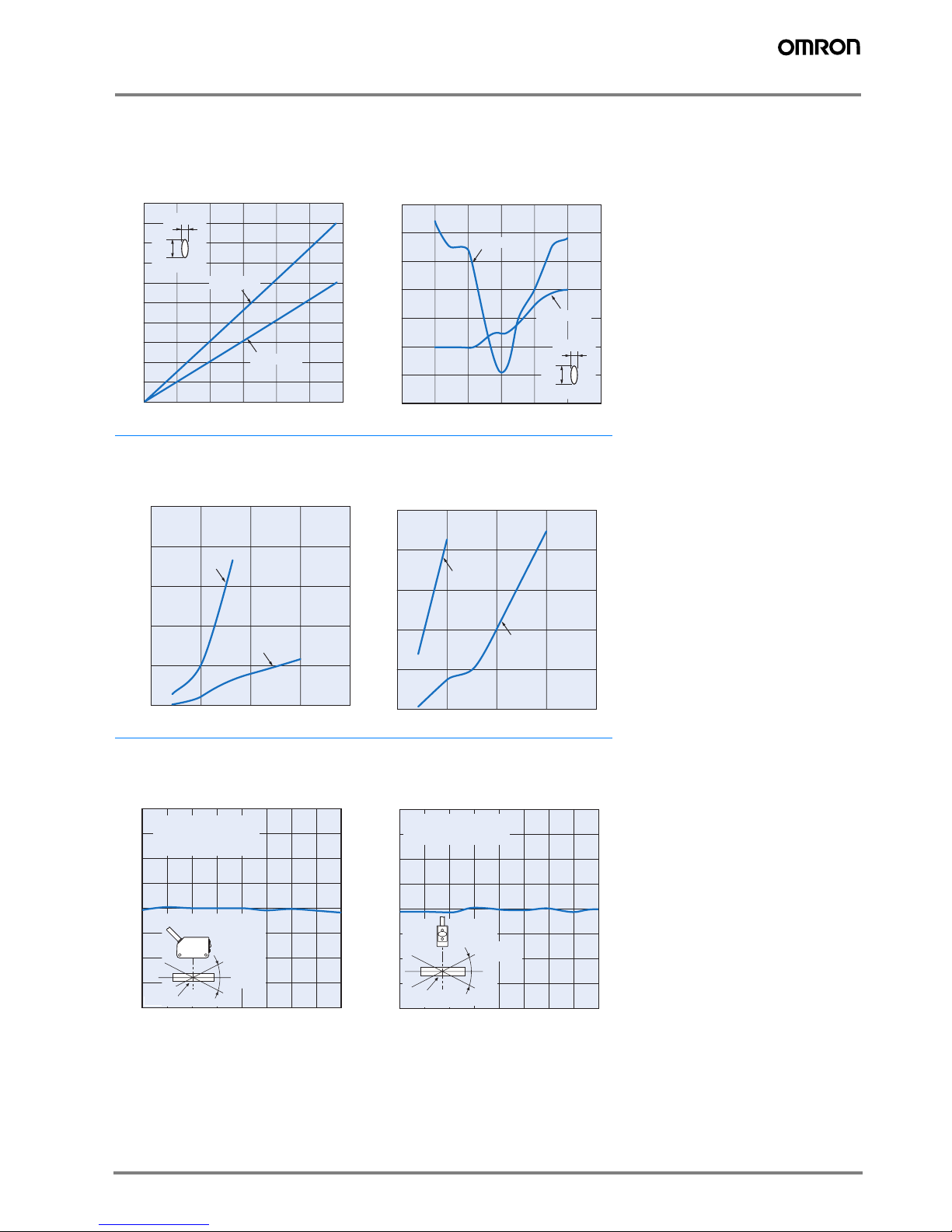
Spot diameter (typical) 5 mm dia. at 3 m 0.5 mm dia. at 300 mm
Standard sensing object Opaque:
12 mm dia. min.
Opaque:
75 mm dia. min. ---
Minimum detectable
object (typical) 6 mm dia. opaque object at 3 m 0.2 mm dia. stainless-steel pin gauge at 300 mm
Differential travel --- 5% max. of set distance
Black/white error --- 5% at 160 mm 5% at 100 mm
Directional angle Receiver: 3 to 15°---
Light source (wavelength) Red LED (655 nm), JIS CLass 1, IEC Class 1, FDA Class II
Power supply voltage 12 to 24 VDC±10%, ripple (p-p): 10% max.
Current consumption Emitter: 15 mA
Receiver: 20 mA 30 mA max.
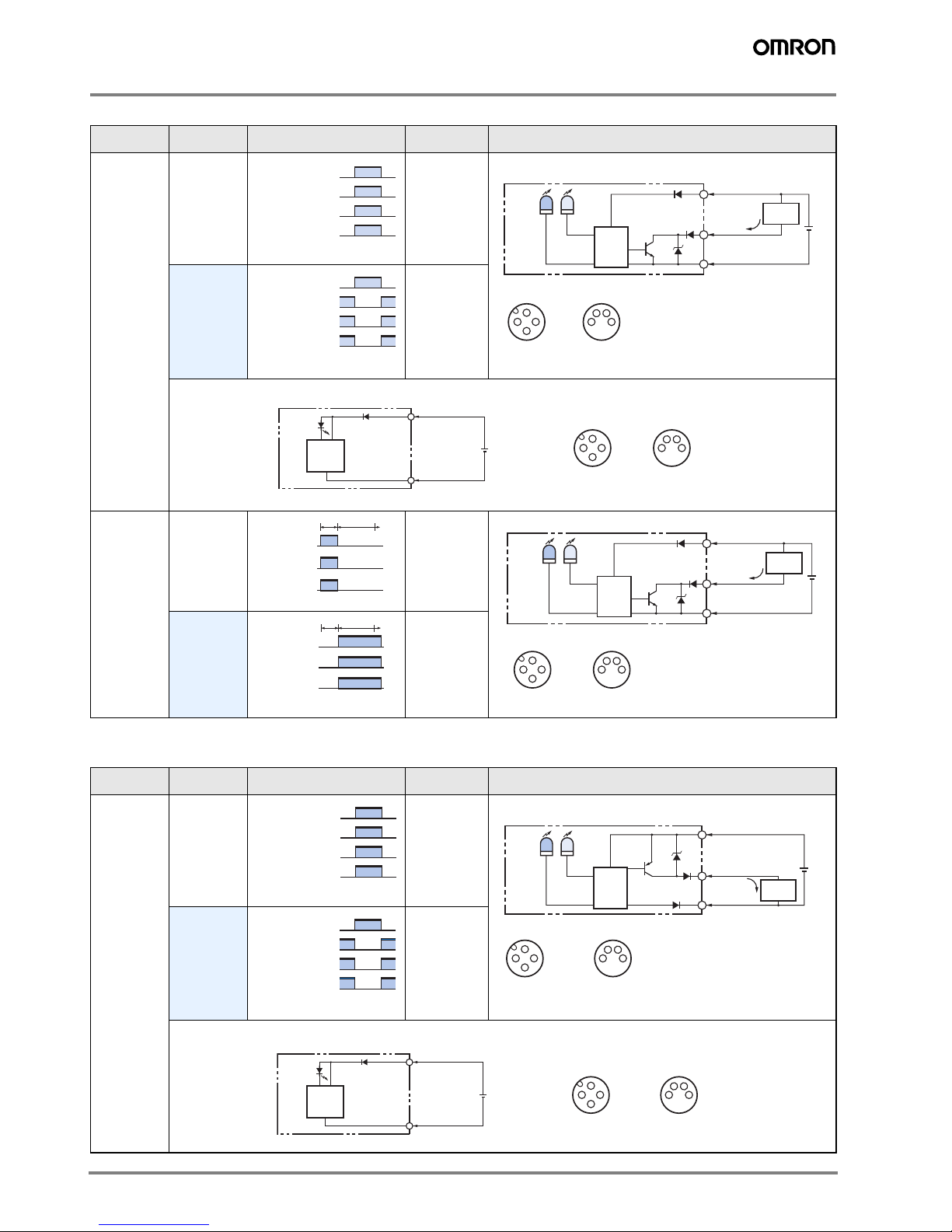
Control output Load power supply voltage: 26.4 VDC max., Load current: 100 mA max., Open collector output
Residual output voltage Load current of less than 10 mA: 1 V max.
Load current of 10 to 100 mA: 2 V max.
Output mode switching Switch to change between light-ON and dark-ON
Protection circuits
Reversed power supply
polarity protection,
Output short-circuit pro-
tection, and Reversed
output polarity protection
Reversed power supply polarity protection, Output short-circuit protection,
Mutual interference prevention, and Reversed output polarity protection
Response time Operate or reset: 1 ms max. Operate or reset:
0.5 ms max.
Sensitivity adjustment One-turn adjuster Five-turn endless adjuster
Ambient illumination
(Receiver side)
Incandescent lamp: 3,000 lx max.
Sunlight: 10,000 lx max.
Ambient temperature range Operating: −10 to 55 °C, Storage: −25 to 70 °C (with no icing or condensation)
Ambient humidity range Operating: 35% to 85%, Storage: 35% to 95% (with no icing or condensation)
Insulation resistance 20 MΩmin. at 500 VDC
Dielectric strength 1,000 VAC, 50/60 Hz for 1 min
Vibration resistance Destruction: 10 to 55 Hz, 1.5 mm double amplitude for 2 hours each in X, Y, and Z directions
Shock resistance Destruction: 500 m/s23 times each in X, Y, and Z directions
Degree of protection IP67 (IEC 60529)
Connection method Pre-wired cable (standard length: 2 m): E3Z-L@@1/-L@@3
Standard M8 Connector: E3Z-L@@6/-L@@8
Indicator
Operation indicator (orange)
Stability indicator (green)
Emitter for Through-bream Models has power indicator (orange) only.

6 Laser Photoelectric Sensor with Built-in Amplifier
Note: An emission stop function can be added to Through-beam Models as a custom function. Ask your OMRON representative for details.
Weight
(packed
state)
Pre-wired cable
(2 m) Approx. 120 g Approx. 65 g
Standard
Connector Approx. 30 g Approx. 20 g
Material
Case PBT (polybutylene terephthalate)
Lens Modified polyarylate
resin Methacrylic resin Modified polyarylate resin
Accessories Instruction manual
(Neither Reflectors nor Mounting Brackets are provided with any of the above models.)
*1. Consult with your OMRON representative if a distance of more than 10 m is required. Models with large custom-size spots can be produced. These make optical
axis adjustment easier and allow the beam to be received more stably by the Receiver even if vibration is present.
Sensing
method Through-beam Retro-reflective with
MSR function Distance-settable (BGS models)
Response Standard response High-speed response
Model
NPN output E3Z-LT61/-LT66 E3Z-LR61/-LR66 E3Z-LL61/-LL66 E3Z-LL63/-LL68
Item PNP output E3Z-LT81/-LT86 E3Z-LR81/-LR86 E3Z-LL81/-LL86 E3Z-LL83/-LL88

7E3Z Laser Models
Engineering Data (Typical)
Parallel Operating Range
Through-beam Models Retro-reflective Models for transparent objects
E3Z-LT@@ E3Z-LR@@
Operating Range at a Set Distance
of 300 mm
Operating Range at a Set Distance
of 40 mm
BGS Models BGS Models
E3Z-LL@@ E3Z-LL@@
Excess Gain vs. Set Distance
Through-beam Models Retro-reflective Models
E3Z-LT@@ E3Z-LR@@
80604020
150
−150
100
−100
50
−50
0
Y
X
Distance X (m)
Distance Y (mm)
3020 2510 155
60
−60
40
−40
20
−20
0
Y
X
E39-R12
E39-R1S
E39-R6
Distance X (m)
Distance Y (mm)
350
300
200
250
500 100 150
−
2.50
2.50
−
2.00
2.00
−
1.00
1.00
−
0.50
−
1.50
1.50
0.50
0.00
Y
X
Sensing object:
100 ×100 mm
white paper
Distance X (mm)
Operating range Y (mm)
605030 4010 20
3
−3
2
−2
1
−1
0
Y
X
Sensing object:
100 ×100 mm
white paper
Distance X (mm)
Operating range Y (mm)
01064212015 30 40 50 7060 80
10000
100
1000
Excess gain ratio (multiple)
Distance (m)
100
10
1
0.1
3010 200
E39-R6
E39-R12
E39-R1S
Distance (m)
Excess gain ratio (multiple)

8 Laser Photoelectric Sensor with Built-in Amplifier
Close Range Characteristics
BGS Models
E3Z-LL@1/-LL@6E3Z-LL@3/-LL@8
Sensing Distance vs. Sensing Object Material
BGS Models
E3Z-LL@1/-LL@6
White Paper with a Set Distance of 40 mm
E3Z-LL@3/-LL@8
White Paper with a Set Distance of 40 mm
E3Z-LL@1/-LL@6
White Paper with a Set Distance of 300 mm
E3Z-LL@3/-LL@8
White Paper with a Set Distance of 100 mm
300 mm
160 mm
40 mm
10 mm 12 mm 0 mm
9 mm
40 mm
350
100
50
300
150
200
250
0
White
paper
Setting:
300 mm
Black
paper
White
paper
Black
paper
Sensing distance (mm)
Setting:
40 mm
Setting:
40 mm
Setting:
160 mm
350
100
50
300
150
200
250
0
White
paper
Black
paper
White
paper
Black
paper
Sensing distance (mm)
300 mm
100 mm
40 mm
10 mm 21 mm 0 mm
9 mm
40 mm
Setting:
300 mm
Setting:
40 mm
Setting:
40 mm
Setting:
100 mm
50
40
10
20
30
0
White
paper
Veneer Card-
board
Black
paper
Black
rubber
SUS Mirror
surface
Material
Sensing distance (mm)
50
40
10
20
30
0
White
paper
Veneer Card-
board
Black
paper
Black
rubber
SUS Mirror
surface
Material
Sensing distance (mm)
350
300
50
150
100
250
200
0
White
paper
Veneer Card-
board
Black
paper
Black
rubber
SUS Mirror
surface
Material
Sensing distance (mm)
120
100
20
60
40
80
0
White
paper
Veneer Card-
board
Black
paper
Black
rubber
SUS Mirror
surface
Material
Sensing distance (mm)

9E3Z Laser Models
Emission Spot Diameter vs. Distance
Through-beam and Retro-reflective Models
(Same for All Models) BGS Models (Same for All Models)
E3Z-LT@@ E3Z-LL@@
E3Z-LR@@
Error vs. Distance
BGS Models
E3Z-LL@1(LL@6) E3Z-LL@3(LL@8)
Angle Characteristics (Vertical) Angle Characteristics (Vertical)
BGS Models BGS Models
E3Z-LL@E3Z-LL@
6030 40 5020100
100
50
10
20
30
40
90
60
70
80
0
Spot shape
a
b
Spot diameter (mm)
Dimension a
Dimension b
Set distance (m)
600300 400 5002001000
1.4
0.2
0.4
0.6
0.8
1.0
1.2
0
Spot shape
a
b
Dimension a
Dimension b
Spot diameter (mm)
Set distance (mm)
4003002001000
2.50
0.50
1.00
1.50
2.00
0.00
Black
paper
White
paper
Set distance (mm)
Hysteresis (%)
4003002001000
2.50
0.50
1.00
1.50
2.00
0.00
Black
paper
White
paper
Set distance (mm)
Hysteresis (%)
20
15
10
5
0
−5
−10
−15
−20
−40 −30 −20 −10 0 10203040
Sensing distance variation (%)
Distance setting: 300 mm
Sensing object: White paper
100 ×100 mm
− θ
+ θ
Inclination angle θ (°)
(Upwards
and
Downwards)
Inclination
angle
Center
line
Sensing
object
− θ
+ θ
Inclination
angle
20
15
10
5
0
−5
−10
−15
−20
−40 −30 −20 −10 0 10203040
Distance setting: 300 mm
Sensing object: White paper
100 ×100 mm
Sensing distance variation (%)
Inclination angle θ(°)
(Left and
Right)
Sensing
object
Center
line

10 Laser Photoelectric Sensor with Built-in Amplifier
I/O Circuit Diagrams
NPN output
PNP output
Model Operation
mode Timing charts Mode selector
switch Output circuit
E3Z-LT61
E3Z-LT66
E3Z-LR61
E3Z-LR66
Light ON L side
(LIGHT ON)
Dark ON D side
(DARK ON)
E3Z-LL61
E3Z-LL66
E3Z-LL63
E3Z-LL68
Light ON L side
(LIGHT ON)
Dark ON D side
(DARK ON)
Model Operation
mode Timing chart Mode selector
switch Output circuit
E3Z-LT81
E3Z-LT86
E3Z-LR81
E3Z-LR86
Light ON L side
(LIGHT ON)
Dark ON D side
(DARK ON)
Incident light
No incident light
ON
OFF
ON
OFF
Operate
Reset
Operation indicator
(orange)
(Between brown and black leads)
Output transistor
Load
(e.g., relay)
4
3
1
100 mA
max.
0 V
ZD
3
1
241
24
3
12 to 24 VDC
Through-beam Receivers, Retro-reflective Models
Pin 2 is not used.
Brown
Black
(Control
output)
Blue
Operation
indicator
Stability
indicator
(Green)
(Orange)
Load
(Relay)
Photo-
electric
Sensor
Main
Circuit
M12 Connector
Pin Arrangement
M8 4-pin Connector
Pin Arrangement
Incident light
No incident light
ON
OFF
ON
OFF
Operate
Reset
Operation indicator
(orange)
(Between brown and black leads)
Output transistor
Load
(e.g., relay)
3
1
3
1
241
24
3
12 to 24 VDC
Through-beam Emitter
Power
indicator
(orange)
Pins 2 and 4
are not used.
Brown
Blue
Photo-elec-
tric Sensor
Main
Circuit
M12 Connector
Pin Arrangement
M8 4-pin Connector
Pin Arrangement
ON
OFF
ON
OFF
Operate
Reset
NEAR FAR
Operation
indicator
(orange)
Output
transistor
Load
(e.g., relay)
(Between brown and black leads)
4
3
1
3
1
241
24
3
100 mA
max.
0 V
ZD
12 to 24 VDC
Pin 4 is not used.
Brown
Black
(Control
output)
Blue
Operation
indicator
Stability
indicator
(Green)
(Orange)
Load
(Relay)
Photo-
electric
Sensor
Main
Circuit
M12 Connector
Pin Arrangement
M8 4-pin Connector
Pin Arrangement
ON
OFF
ON
OFF
Operate
Reset
NEAR FAR
Operation
indicator
(orange)
Output
transistor
Load
(e.g., relay)
(Between brown and black leads)
Incident light
No incident light
ON
OFF
ON
OFF
Operate
Reset
Operation indicator
(orange)
(Between blue and black leads)
Output transistor
Load
(e.g., relay) 4
1
3
3
1
241
24
3
Through-beam Receivers, Retro-reflective Models
100 mA
max.
0 V
ZD
12 to 24 VDC
Pin 2 is not used.
Brown
Black
(Control
output)
Blue
Operation
indicator
Stability
indicator
(Green)
(Orange)
Load
(Relay)
Photo-
electric
Sensor
Main
Circuit
M12 Connector
Pin Arrangement
M8 4-pin Connector
Pin Arrangement
Incident light
No incident light
ON
OFF
ON
OFF
Operate
Reset
Operation indicator
(orange)
(Between blue and black leads)
Output transistor
Load
(e.g., relay)
3
1
3
1
241
24
3
12 to 24 VDC
Through-beam Emitter
Power
indicator
(orange)
Pins 2 and 4 are not used.
Brown
Blue
Photo-elec-
tric Sensor
Main
Circuit
M12 Connector
Pin Arrangement
M8 4-pin Connector
Pin Arrangement

11E3Z Laser Models
Plugs (Sensor I/O Connectors)
M8 4-pin Connectors
M12 Connectors
Nomenclature
E3Z-LL81
E3Z-LL86
E3Z-LL83
E3Z-LL88
Light ON L side
(LIGHT ON)
Dark ON D side
(DARK ON)
Model Operation
mode Timing chart Mode selector
switch Output circuit
ON
OFF
ON
OFF
Operate
Reset
NEAR FAR
Operation
indicator
(orange)
Output
transistor
Load
(e.g., relay)
(Between blue and black leads)
3
1
241
24
3
4
1
3
100 mA
max.
0 V
ZD
12 to 24 VDC
Pin 4 is not used.
Brown
Black
(Control
output)
Operation
indicator
Stability
indicator
(Green)
(Orange)
Load
(Relay)
Photo-
electric
Sensor
Main
Circuit
M12 Connector
Pin Arrangement
M8 4-pin Connector
Pin Arrangement
Blue
ON
OFF
ON
OFF
Operate
Reset
NEAR FAR
Operation
indicator
(orange)
Output
transistor
Load
(e.g., relay)
(Between blue and black leads)
2
4
1
3
1
2
3
4
XS3F-M421-402-A
XS3F-M421-405-A
XS3F-M422-402-A
XS3F-M422-405-A
Brown
White
Blue
Black
Wire color
2
4
13
1
2
3
4
Pin No.
XS2F-D421-DC0-A
XS2F-D421-GC0-A
XS2F-D422-DC0-A
XS2F-D422-GC0-A
Brown
Blue
Black
Wire color
Distance adjuster
(5-turn endless)
Stability indicator
(green)
Mode selector
switch
Operation indicator
(orange)
Sensitivity adjuster Stability indicator
(green)
Operation indicator
(orange)
Mode selector
switch
Sensors with Sensitivity Adjustment and Mode
Selector Switch
Through-beam Models
E3Z-LT@@ (Receiver)
Retro-reflective Models
Distance-settable Sensor
BGS Models
E3Z-LL@@

12 Laser Photoelectric Sensor with Built-in Amplifier
Safety Precautions
Refer to Warranty and Limitations of Liability on page 20.
This product is not designed or rated for ensuring
safety of persons. Do not use it for such purpose.
To ensure safe use of laser products, do not allow
the laser beam to enter your eye. Direct exposure
may adversely affect your eyesight.
Do not connect an AC power supply to the Sensor.
If AC power (100 VAC or more) is supplied to the
Sensor, it may explode or burn.
Be sure to abide by the following precautions for the safe op-
eration of the Sensor.
Operating Environment
Do not use the Sensor in locations with explosive or flamma-
ble gas.
Wiring
Power Supply Voltage and Output Load Power Supply
Voltage
Make sure that the power supply to the Sensor is within the
rated voltage range. If a voltage exceeding the rated voltage
range is supplied to the Sensor, it may explode or burn.
Power Supply Voltage
The maximum power supply voltage is 26.4 VDC. Applying a
voltage exceeding the rated range may damage the Sensor or
cause burning.
Load
Do not use a load that exceeds the rated load.
Load Short-circuiting
Do not short-circuit the load, otherwise the Sensor may be
damaged or it may burn.
Connection without Load
Do not connect the power supply to the Sensor with no load
connected, otherwise the internal elements may explode or
burn. Always connect a load when wiring.
Do not use the product in atmospheres or environments that
exceed product ratings.
Usage Environment
Water Resistance
The Sensor is rated IP67. Do not use it in water, in the rain, or
outdoors.
Ambient Environment
Do not install the product in the following locations. Doing so
may result in product failure or malfunction.
• Locations subject to excess dust and dirt
• Locations subject to direct sunlight
• Locations subject to corrosive gas
• Locations subject to organic solvents
• Locations subject to shock or vibration
• Locations subject to exposure to water, oil, or chemicals
• Locations subject to high humidity or condensation
Designing
Power Reset Time
The Sensor is ready to operate 100 ms after the Sensor is
turned ON. If the load and Sensor are connected to indepen-
dent power supplies respectively, be sure to turn ON the Sen-
sor before supplying power to the load.
Wiring
Avoiding Malfunctions
If using the Sensor with an inverter or servomotor, always
ground the FG (frame ground) and G (ground) terminals, oth-
erwise the Sensor may malfunction.
Mounting
Mounting the Sensor
• If Sensors are mounted face-to-face, make sure that the op-
tical axes are not in opposition to each other. Otherwise,
mutual interference may result.
• Always install the Sensor carefully so that the aperture an-
gle range of the Sensor will not cause it to be directly ex-
posed to intensive light, such as sunlight, fluorescent light,
or incandescent light.
• Do not strike the Photoelectric Sensor with a hammer or
any other tool during the installation of the Sensor, or the
Sensor will lose its water-resistive properties.
• Use M3 screws to mount the Sensor.
• When mounting the case, make sure that the tightening
torque applied to each screw does not exceed 0.54 N·m.
!Warning
!Caution
Precautions for Safe Use
Correct Use

13E3Z Laser Models
Metal Connectors
• Always turn OFF the power supply to the Sensor before
connecting or disconnecting the metal connector.
• Hold the connector cover to connect or disconnect it.
• Secure the connector cover by hand. Do not use pliers, oth-
erwise the connector may be damaged.
• Use a tightening torque of 0.3 to 0.4 N·m for M8 connectors
and 0.4 to 0.5 N·m for M12 connectors. Vibration may
cause the connectors to become loose and reduce the de-
gree or protection is the tightening torque is not sufficient.
Mounting Direction for Distance-settable Models
• Make sure that the sensing
side of the Sensor is parallel
with the surface of the sensing
objects. Normally, do not in-
cline the Sensor towards the
sensing object.
If the sensing object has a glossy
surface, however, incline the
Sensor by 5°to 10°as shown in
the illustration, provided that the
Sensor is not influenced by
background objects.
• If there is a mirror-like object below the Sensor, the Sensor
may not operate stably. Therefore, incline the Sensor or
separate the Sensor from the mirror-like object as shown
below.
• Do not install the Sensor in the wrong direction. Refer to the
following illustration.
Install the Sensor as shown in the following illustration if each
sensing object greatly differs in color or material.
Adjusting Distance-settable Models
Indicator Operation
Note: If the stability indicator is lit, the detection/no detection status is stable
within the rated ambient operating temperature (−10 to 55°C).
Inspection and Maintenance
Cleaning
Never use paint thinners or other organic solvents to clean the
surface of the product.
Sensing side
Surface of sensing
object
Glossy object
Sensing
object
Mirror-like object
Sensing
object
Moving direction
Moving direction
Moving
direction
Sensing
object
Sensing
object
Correct Incorrect
Correct
Moving direction
Moving direction
Correct Incorrect
ON
OFF
ON
OFF
ON
OFF
ON
OFF
Stability
(green)
Operation
(orange)
Stability
(green)
Operation
(orange)
L/ON
D/ON
BGS
NEAR region
Stable NEAR Stable FAR
FAR region
Unstable NEAR Unstable FAR
Distance threshold
(settable)

14 Laser Photoelectric Sensor with Built-in Amplifier
Dimensions (Unit: mm)
Sensors
Through-beam
Pre-wired Models
E3Z-LT61
E3Z-LT81
20 8
17
2.1
25.4
Two, M3
31
10.410.8
Optical axis
Power indicator (orange)
Lens
Emitter
4-dia. vinyl-insulated round cable with
2 conductors (Conductor cross section:
0.2 mm2, Insulator diameter: 1.1 mm),
Standard length: 2 m
15.5
8
18
3.5 dia.
Pins 2 and 4 are not
used.
Terminal
No.
Specifi-
cations
1+V
2 ---
30V
4 --- M12×1
1
3
2
4
M8
24
13
*4-dia. vinyl-insulated round cable with
2 or 3 conductors,
Standard length: 0.3 m
M12 Pre-wired Connector
(E3Z-LT@@-M1J)
M8 Pre-wired Connector
(Ask your OMRON representative for details.)
*4-dia. vinyl-insulated round cable with
2 or 3 conductors,
Standard length: 0.3 m
* The Emitter cable has two conductors and the
Receiver cable has three conductors.
17
2.1
25.4
Two, M3
31
15.5
11
18
20
12.45
8.8
3.2
10.410.8
4.3
7.2
Optical axis
Stability indicator (green)
Operation indicator (orange)
Sensitivity adjuster
Mode selector switch
Lens
Receiver
V4-dia. vinyl-insulated round cable with
3 conductors (Conductor cross section: 0.2 mm2,
Insulator diameter: 1.1 mm),
Standard length: 2m
Pin 2 is not used.
Terminal
No.
Specifi-
cations
1+V
2 ---
30V
4 Output
Through-beam
Standard Connector
Models
E3Z-LT66
E3Z-LT86 17
2.1
25.431
10.4 Two,
M3
20 8
10.410.8
9.75 M8 connector
Lens
Optical axis
Power indicator (orange)
Emitter
15.5
8
18.1
3.5 dia.
17
2.1
25.4
9.75
31
10.4
15.5
11
18
20
12.45
8.8
3.2
10.410.8
4.3
7.2
Two,
M3
M8 connector
Lens
Optical axis
Stability indicator (green)
Operation indicator (orange)
Sensitivity adjuster
Receiver
Mode selector switch

15E3Z Laser Models
20
12.6
8.8
3.2
17
2.1
25.431
15.5
4
19.5 4
10.410.8
4.3
Two, M2
Stability indicator (green)
Operation indicator (orange)
Lens
Receiver
Optical axis
Emitter
Sensing adjuster
Mode selector switch
4-dia. vinyl-insulated round cable with
2 conductors (Conductor cross section:
0.2 mm2, Insulator diameter: 1.1 mm),
Standard length: 2m
Retro-re
f
lective Models
Pre-wired Models
E3Z-LR61
E3Z-LR81
M12 ×1
1
3
2
4
M8
24
13
M8 Pre-wired Connector
(Ask your OMRON representative for details.)
*4-dia. vinyl-insulated round cable with
3 conductors,
Standard length: 0.3 m
*4-dia. vinyl-insulated round cable with
3 conductors,
Standard length: 0.3 m
M12 Pre-wired Connector
(E3Z-LR@@-M1J)
Terminal
No.
Specifi-
cations
1+V
2 ---
30V
4 Output
17
25.431
10.4
9.75
20
12.6
8.8
3.2
15.5
4
19.5 4
10.410.8
4.3
Two, M3
Stability indicator (green)
Operation indicator
(orange)
M8 connector
Lens
Receiver
Optical axis
Emitter
Sensing adjuster
Mode selector switch
Retro-re
f
lective Models
Standard Connector Models
E3Z-LR66
E3Z-LR86
Two, M3
Distance adjuster
4.3
8
12.7
20
10.8 10.4
17
3118 4
4
25.4
2.1
13.5
Stability indicator (green)
Operation indicator (orange)
Two, 7-dia. lenses
Receiver
Optical axis
Emitter
Mode selector switch
4-dia. vinyl-insulated round cable with 4
conductors (Conductor cross section:
0.2 mm2, Insulator diameter: 1.1 mm),
Standard length: 0.5 m, 2m
M12×1
1
3
2
4
M8
24
13
M8 Pre-wired Connector
(Ask your OMRON representative for details.)
*4-dia. vinyl-insulated round cable with
4 conductors,
Standard length: 0.3 m
*4-dia. vinyl-insulated round cable with
4 conductors,
Standard length: 0.3 m
M12 Pre-wired Connector
(E3Z-LL@@-M1J)
Terminal
No.
Specifi-
cations
1+V
2---
30V
4 Output
B
GS
Models
Pre-wired Models
E3Z-LL61
E3Z-LL81
E3Z-LL63
E3Z-LL83
Two,
M3
Distance adjuster
4.3
8
12.7
20
10.8 10.4
17
31
10.4
18 4
4
25.4
2.1
13.5
9.75
Stability indicator (green)
Operation indicator (orange)
Two, 7-dia. lenses
Receiver
Optical axis
Emitter
Mode selector switch
M8 connector
B
GS
Models
Standard M8
Connector Models
E3Z-LL66
E3Z-LL86
E3Z-LL68
E3Z-LL88

16 Laser Photoelectric Sensor with Built-in Amplifier
Accessories (Order Separately)
Slit
E39-S65A
0.5 dia.
32.2
4.5
3.4
0.2
15.5
10.4
Material
SUS301 stainless steel
Reflector
E39-R1S
Materials
Reflective surface: Acrylic
Rear surface: ABS
34
40.3
5259.9
2.7
8
1.6
7.5
7
Two, 3.5 dia.
Reflector
E39-R6
60 40
34
40
52
3.5
3.5
4.8
Materials
Reflective surface: Acrylic
Rear surface: ABS
37
R3.7
23
15
30
23
45
5.5
2.9 Four, R3
Four, R1.4
R3.7
Two,
3.4 dia.
Reflector
E39-R12

17E3Z Laser Models

18 Laser Photoelectric Sensor with Built-in Amplifier

19E3Z Laser Models

20 Laser Photoelectric Sensor with Built-in Amplifier
WARRANTY
OMRON’s exclusive warranty is that the products are free from
defects in materials and workmanship for a period of one year (or
other period if specified) from date of sale by OMRON.
OMRON MAKES NO WARRANTY OR REPRESENTATION,
EXPRESS OR IMPLIED, REGARDING NON-INFRINGEMENT,
MERCHANTABILITY, OR FITNESS FOR PARTICULAR PURPOSE
OF THE PRODUCTS. ANY BUYER OR USER ACKNOWLEDGES
THAT THE BUYER OR USER ALONE HAS DETERMINED THAT
THE PRODUCTS WILL SUITABLY MEET THE REQUIREMENTS
OF THEIR INTENDED USE. OMRON DISCLAIMS ALL OTHER
WARRANTIES, EXPRESS OR IMPLIED.
LIMITATIONS OF LIABILITY
OMRON SHALL NOT BE RESPONSIBLE FOR SPECIAL,
INDIRECT, OR CONSEQUENTIAL DAMAGES, LOSS OF PROFITS
OR COMMERCIAL LOSS IN ANY WAY CONNECTED WITH THE
PRODUCTS, WHETHER SUCH CLAIM IS BASED ON CONTRACT,
WARRANTY, NEGLIGENCE, OR STRICT LIABILITY.
In no event shall responsibility of OMRON for any act exceed the
individual price of the product on which liability is asserted.
IN NO EVENT SHALL OMRON BE RESPONSIBLE FOR
WARRANTY, REPAIR, OR OTHER CLAIMS REGARDING THE
PRODUCTS UNLESS OMRON’S ANALYSIS CONFIRMS THAT
THE PRODUCTS WERE PROPERLY HANDLED, STORED,
INSTALLED, AND MAINTAINED AND NOT SUBJECT TO
CONTAMINATION, ABUSE, MISUSE, OR INAPPROPRIATE
MODIFICATION OR REPAIR.
SUITABILITY FOR USE
THE PRODUCTS CONTAINED IN THIS DOCUMENT ARE NOT
SAFETY RATED. THEY ARE NOT DESIGNED OR RATED FOR
ENSURING SAFETY OF PERSONS, AND SHOULD NOT BE
RELIED UPON AS A SAFETY COMPONENT OR PROTECTIVE
DEVICE FOR SUCH PURPOSES. Please refer to separate catalogs
for OMRON's safety rated products.
OMRON shall not be responsible for conformity with any standards,
codes, or regulations that apply to the combination of products in the
customer’s application or use of the product.
At the customer’s request, OMRON will provide applicable third party
certification documents identifying ratings and limitations of use that
apply to the products. This information by itself is not sufficient for a
complete determination of the suitability of the products in
combination with the end product, machine, system, or other
application or use.
The following are some examples of applications for which particular
attention must be given. This is not intended to be an exhaustive list
of all possible uses of the products, nor is it intended to imply that the
uses listed may be suitable for the products:
• Outdoor use, uses involving potential chemical contamination or
electrical interference, or conditions or uses not described in this
document.
• Nuclear energy control systems, combustion systems, railroad
systems, aviation systems, medical equipment, amusement
machines, vehicles, safety equipment, and installations subject to
separate industry or government regulations.
• Systems, machines, and equipment that could present a risk to life
or property.
Please know and observe all prohibitions of use applicable to the
products.
NEVER USE THE PRODUCTS FOR AN APPLICATION INVOLVING
SERIOUS RISK TO LIFE OR PROPERTY WITHOUT ENSURING
THAT THE SYSTEM AS A WHOLE HAS BEEN DESIGNED TO
ADDRESS THE RISKS, AND THAT THE OMRON PRODUCT IS
PROPERLY RATED AND INSTALLED FOR THE INTENDED USE
WITHIN THE OVERALL EQUIPMENT OR SYSTEM.
PERFORMANCE DATA
Performance data given in this document is provided as a guide for
the user in determining suitability and does not constitute a warranty.
It may represent the result of OMRON’s test conditions, and the
users must correlate it to actual application requirements. Actual
performance is subject to the OMRON Warranty and Limitations of
Liability.
CHANGE IN SPECIFICATIONS
Product specifications and accessories may be changed at any time
based on improvements and other reasons.
It is our practice to change model numbers when published ratings or
features are changed, or when significant construction changes are
made. However, some specifications of the product may be changed
without any notice. When in doubt, special model numbers may be
assigned to fix or establish key specifications for your application on
your request. Please consult with your OMRON representative at any
time to confirm actual specifications of purchased products.
DIMENSIONS AND WEIGHTS
Dimensions and weights are nominal and are not to be used for
manufacturing purposes, even when tolerances are shown.
ERRORS AND OMISSIONS
The information in this document has been carefully checked and is
believed to be accurate; however, no responsibility is assumed for
clerical, typographical, or proofreading errors, or omissions.
PROGRAMMABLE PRODUCTS
OMRON shall not be responsible for the user’s programming
of a programmable product, or any consequence thereof.
In the interest of product improvement, specifications are subject to change without notice.
Cat. No. E368-E2-01-X
OMRON EUROPE B.V.
Wegalaan 67-69,
NL-2132 JD, Hoofddorp,
The Netherlands
Phone: +31 23 568 13 00
Fax: +31 23 568 13 88
www.eu.omron.com
Table of contents
Other Omron Accessories manuals

Omron
Omron E2Q5 User manual

Omron
Omron ZFV-SC150 Series User manual

Omron
Omron E3NT-L User manual

Omron
Omron F3M-S825-1 User manual

Omron
Omron E3F2-Z User manual

Omron
Omron TL User manual

Omron
Omron ZFX-SR10-1 User manual

Omron
Omron ZFV-SC10 Series User manual

Omron
Omron FZ Series User manual

Omron
Omron ZFX-C-CD User manual

Omron
Omron ZX2 Series User manual

Omron
Omron E3NW-ECT User manual

Omron
Omron E2C-EDA Series User manual

Omron
Omron F3SJ-A series User manual

Omron
Omron E2EQ User manual

Omron
Omron TL-T User manual

Omron
Omron ZG - User manual

Omron
Omron ZFV-SC50 Series User manual

Omron
Omron F3C-AA42-1 User manual

Omron
Omron E3S-CR62/67 Manual