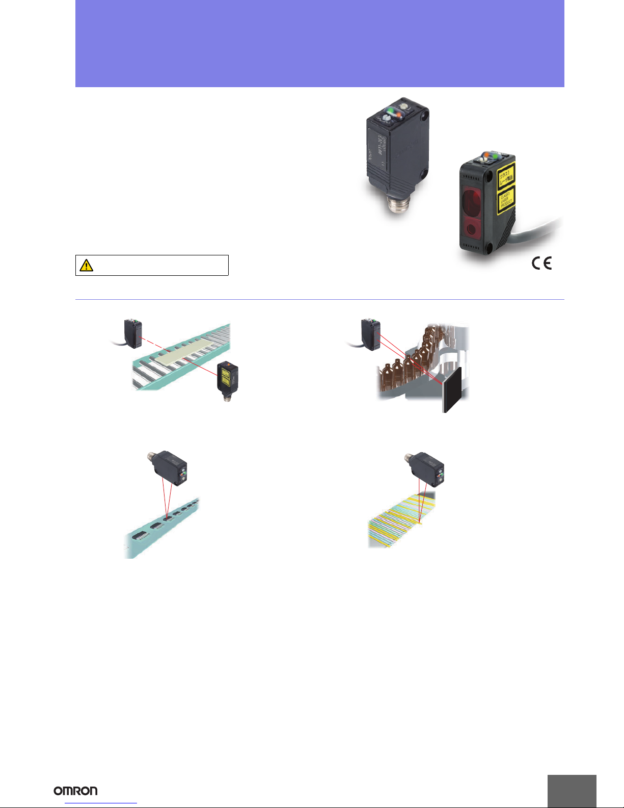
Omron E3Z-LT61 User manual

1
CSM_E3Z-LT_LR_LL_DS_E_6_4
Compact Laser Photoelectric Sensor with Built-in Amplifier
E3Z-LT/LR/LL
Applications
Greatly Enhanced Beam Visibility
for Easier Optical Axis Adjustment of Sensors
Detect the sides of large tiles.
Detect chip components on tape.
Long-distance Sensing
at 300 mm (White Paper)
Reliable Detection of
Small Objects and
Narrow Gaps with the Small Spot
Count bottles.
Detect protruding straws.
A Low Black/White Error for
Applications with Mixed Colors
Compact and Reliable
Laser Photoelectric Sensor
• Safety and reliability with laser class 1 (JIS and IEC).
• Product lineup includes models with distance setting without influence of
color.
• Maximum ambient operating temperature of 55°C and water-proof
construction in E3Z class.
Be sure to read Safety Precautions on
page 9.

E3Z-LT/LR/LL
2
Ordering Information
Sensors (Refer to Dimensions on page 11.)
*1. The Reflector is sold separately. Select the Reflector model most suited to the application.
*2. Values in parentheses indicate the minimum required distance between the Sensor and Reflector.
*3. Pre-wired Models with a 0.5-m cable are also available for these products. When ordering, specify the cable length by adding “0.5M” to the end of the model number
(e.g., E3Z-LT61 0.5M).
M12 Pre-wired Connector Models are also available. When ordering, add “-M1J” to the end of the model number (e.g., E3Z-LT61-M1J). The cable is 0.3 m long.
Also, the following connection forms can be manufactured. Ask your OMRON representative for details.
• Pre-wired Models with 1-m or 5-m cables
• Pre-wired Connector Models with M8 4-pin connectors or M8 3-pin connectors.
*4. Through-beam Sensors are normally sold in sets that include both the Emitter and Receiver.
Orders for individual Emitters and Receivers are accepted. (Modifications are required for some models. Ask your OMRON representative for details.)
Accessories
Slits (A Slit is not provided with a Through-beam Sensor. Order a Slit separately if required.) (Refer to Dimensions on page 14.)
Reflectors
(A Reflector is required for Retro-reflective Sensors: A Reflector is not provided with the Sensor. Be sure to order a Reflector.)
(Refer to Dimensions on page 14.)
Sensing method Appearance Connection
method
Response
time Sensing distance Model
NPN output PNP output
Through-beam
(Emitter + Receiver) *4
Pre-wired
(2 m)*3
1 ms
E3Z-LT61 2M E3Z-LT81 2M
Emitter E3Z-T61-L 2M
Receiver E3Z-T61-D 2M Emitter E3Z-T81-L 2M
Receiver E3Z-T81-D 2M
Connector
(M8, 4 pins)
E3Z-LT66 E3Z-LT86
Emitter E3Z-T66-L
Receiver E3Z-T66-D Emitter E3Z-T86-L
Receiver E3Z-T86-D
Retro-reflective with
MSR function
Pre-wired
(2 m)*3E3Z-LR61 2M E3Z-LR81 2M
Connector
(M8, 4 pins) E3Z-LR66 E3Z-LR86
Distance-settable
(BGS Models)
Pre-wired
(2 m)*3E3Z-LL61 2M E3Z-LL81 2M
Connector
(M8, 4 pins) E3Z-LL66 E3Z-LL86
Pre-wired
(2 m)*30.5 ms
E3Z-LL63 2M E3Z-LL83 2M
Connector
(M8, 4 pins) E3Z-LL68 E3Z-LL88
Slit width Sensing distance Minimum detectable object
(typical) Model Contents
0.5 mm dia. 3 m 0.1 mm dia. E39-S65A
One set
(contains Slits for both the
Emitter and Receiver)
Name Sensing distance (typical) Model Remarks
Reflector
15 m (300 mm) E39-R1 • Retro-reflective models are not provided with Reflectors.
• Separate the Sensor and the Reflector by at least the
distance given in parentheses.
• The MSR function is enabled.
7 m (200 mm) E39-R12
7 m (200 mm) E39-R6
Red light
60 m
*1(Using E39-R12)
(Using E39-R1)
7 m
(200 mm)
(Using E39-R6)
15 m
(300 mm)
7 m
(200 mm)
*2
20 to 40 mm
(Min. distance set)
20 to 300 mm
(Max. distance set)
25 to 40 mm
(Min. distance set)
25 to 300 mm
(Max. distance set)

E3Z-LT/LR/LL
3
Mounting Brackets A Mounting Bracket is not provided with the Sensor. Order a Mounting Bracket separately if required.
(Refer to Dimensions on E39-L/F39-L/E39-S/E39-R.)
Note: When using a Through-beam Sensor, order one Mounting Bracket for the Receiver and one for the Emitter
* Cannot be used for Standard Connector models.
Sensor I/O Connectors
(Models for Connectors and Pre-wired Connectors: A Connector is not provided with the Sensor. Be sure to order a Connector separately.)
(Refer to Dimensions on XS3, XS2)
Note: When using a Through-beam Sensor, order one Mounting Bracket for the Receiver and one for the Emitter
*1. The connector will not rotate after connecting.
*2. The cable is fixed at an angle of 180° from the sensor emitter/receiver surface.
Appear-
ance Model Quantity Remarks Appear-
ance Model Quantity Remarks
E39-L153 1
Mounting Brackets
E39-L98 1 Metal Protective Cover Bracket *
E39-L104 1E39-L150 1 set
(Sensor adjuster)
Easily mounted to the aluminum
frame rails of conveyors and
easily adjusted.
For left to right adjustment
E39-L43 1 Horizontal Mounting Bracket *
E39-L151 1 set
E39-L142 1Horizontal Protective Cover
Bracket *
E39-L44 1 Rear Mounting Bracket E39-L144 1Compact Protective Cover
Bracket (For E3Z only) *
Size Cable Appearance Cable type Model
M8
Standard
2 m
4-wire
XS3F-M421-402-A
5 m XS3F-M421-405-A
2 m XS3F-M422-402-A
5 m XS3F-M422-405-A
M12
(For -M1J
models)
2 m
3-wire
XS2F-D421-DC0-A
5 m XS2F-D421-GC0-A
2 m XS2F-D422-DC0-A
5 m XS2F-D422-GC0-A
Straight *1
L-shaped *1 *2
Straight *1
L-shaped *1

E3Z-LT/LR/LL
4
Ratings and Specifications
Sensing
method Through-beam Retro-reflective with MSR
function Distance-settable (BGS models)
Response Standard response High-speed response
Model
NPN
output E3Z-LT61/-LT66 E3Z-LR61/-LR66 E3Z-LL61/-LL66 E3Z-LL63/-LL68
Item PNP
output E3Z-LT81/-LT86 E3Z-LR81/-LR86 E3Z-LL81/-LL86 E3Z-LL83/-LL88
Sensing distance 60 m
0.3
to
15 m
(when using E39-R1)
0.2
to
7 m
(when using E39-R12)
0.2
to
7 m
(when using E39-R6)
White paper (100 ×100 mm):
20 to 300 mm
Black paper (100 ×100 mm):
20 to 160 mm
White paper (100 ×100 mm):
25 to 300 mm
Black paper (100 ×100 mm):
25 to 100 mm
Set distance range ---
White paper (100 ×100 mm):
40 to 300 mm
Black paper (100 ×100 mm):
40 to 160 mm
White paper (100 ×100 mm):
40 to 300 mm
Black paper (100 ×100 mm):
40 to 100 mm
Spot diameter (typical) 5-mm dia. at 3 m 0.5-mm dia. at 300 mm
Standard sensing object Opaque: 12-mm dia. min. Opaque: 75-mm dia. min. ---
Minimum detectable
object (typical) 6-mm-dia. opaque object at 3 m 0.2-mm-dia. stainless-steel pin gauge at 300 mm
Differential travel --- 5% max. of set distance
Black/white error --- 5% at 160 mm 5% at 100 mm
Directional angle Receiver: 3 to 15°---
Light source (wavelength) Red LD (655 nm), JIS CLass 1, IEC Class 1, FDA Class II
Power supply voltage 12 to 24 VDC±10%, ripple (p-p): 10% max.
Current consumption 35 mA (Emitter 15 mA,
Receiver 20 mA) 30 mA max.
Control output Load power supply voltage: 26.4 VDC max., Load current: 100 mA max., Open collector output
Residual output voltage Load current of less than 10 mA: 1 V max.
Load current of 10 to 100 mA: 2 V max.
Output mode switching Switch to change between light-ON and dark-ON
Protection circuits
Reversed power supply
polarity protection, Output
short-circuit protection, and
Reversed output polarity
protection
Reversed power supply polarity protection, Output short-circuit protection, Mutual interference pre-
vention, and Reversed output polarity protection
Response time Operate or reset: 1 ms max. Operate or reset: 0.5 ms max.
Sensitivity adjustment One-turn adjuster Five-turn endless adjuster
Ambient illumination
(Receiver side)
Incandescent lamp: 3,000 lx max.
Sunlight: 10,000 lx max.
Ambient temperature range Operating: −10 to 55°C, Storage: −25 to 70°C (with no icing or condensation)
Ambient humidity range Operating: 35% to 85%, Storage: 35% to 95% (with no icing or condensation)
Insulation resistance 20 MΩmin. at 500 VDC
Dielectric strength 1,000 VAC, 50/60 Hz for 1 min
Vibration resistance Destruction: 10 to 55 Hz, 1.5-mm double amplitude for 2 hours each in X, Y, and Z directions
Shock resistance Destruction: 500 m/s23 times each in X, Y, and Z directions
Degree of protection IP67 (IEC 60529)
Connection method Pre-wired cable (standard length: 2 m): E3Z-L@@1/-L@@3
Standard M8 Connector: E3Z-L@@6/-L@@8
Indicator
Operation indicator (orange)
Stability indicator (green)
Emitter for Through-bream Models has power indicator (orange) only.
Weight
(packed
state)
Pre-wired cable
(2 m) Approx. 120 g Approx. 65 g
Standard
Connector Approx. 30 g Approx. 20 g
Material Case PBT (polybutylene terephthalate)
Lens Modified polyarylate resin Methacrylic resin Modified polyarylate resin
Accessories Instruction manual (Neither Reflectors nor Mounting Brackets are provided with any of the above models.)

E3Z-LT/LR/LL
5
Engineering Data (Typical)
Parallel Operating Range
Through-beam Models Through-beam Models Retro-reflective Models
E3Z-LT@@ E3Z-LT@@ + E39-S65A E3Z-LR@@
Operating Range at a Set Distance
of 300 mm
Operating Range at a Set Distance
of 40 mm
BGS Models BGS Models
E3Z-LL@@ E3Z-LL@@
Excess Gain vs. Set Distance
Through-beam Models Retro-reflective Models
E3Z-LT@@ E3Z-LR@@
Close Range Characteristics
BGS Models
E3Z-LL@1/-LL@6E3Z-LL@3/-LL@8
80604020
150
−150
100
−100
50
−50
0
Y
X
Distance X (m)
Distance Y (mm)
20
−20
15
−15
−10
10
5
−5
0810462
Distance (mm)
Distance (m)
3020 2510 155
60
−60
40
−40
20
−20
0
Y
X
E39-R12
E39-R1
E39-R6
Distance X (m)
Distance Y (mm)
350
300
200
250
500 100 150
−
2.50
2.50
−
2.00
2.00
−
1.00
1.00
−
0.50
−
1.50
1.50
0.50
0.00
Y
X
Sensing object:
100 ×100 mm
white paper
Distance X (mm)
Operating range Y (mm)
605030 4010 20
3
−3
2
−2
1
−1
0
Y
X
Sensing object:
100 ×100 mm
white paper
Distance X (mm)
Operating range Y (mm)
02010 30 40 50 7060 80
10000
100
1000
Distance (m)
Excess gain ratio (multiple)
100
10
1
0.1
3010 200
E39-R6
E39-R12
E39-R1
Distance (m)
Excess gain ratio (multiple)
300 mm
160 mm
40 mm
10 mm 12 mm 0 mm
9 mm
40 mm
350
100
50
300
150
200
250
0
White
paper
Setting:
300 mm
Black
paper
White
paper
Black
paper
Sensing distance (mm)
Setting:
40 mm
Setting:
40 mm
Setting:
160 mm
350
100
50
300
150
200
250
0
White
paper
Black
paper
White
paper
Black
paper
Sensing distance (mm)
300 mm
100 mm
40 mm
10 mm 21 mm 0 mm
9 mm
40 mm
Setting:
300 mm
Setting:
40 mm
Setting:
40 mm
Setting:
100 mm

E3Z-LT/LR/LL
6
Sensing Distance vs. Sensing Object Material
BGS Models
E3Z-LL@1/-LL@6
White Paper with a Set Distance of 40 mm
E3Z-LL@3/-LL@8
White Paper with a Set Distance of 40 mm
E3Z-LL@1/-LL@6
White Paper with a Set Distance of 300 mm
Emission Spot Diameter vs. Distance
Through-beam and Retro-reflective
Models (Same for All Models)
BGS Models (Same for All Models)
E3Z-LL@3/-LL@8
White Paper with a Set Distance of 100 mm E3Z-LT@@, E3Z-LR@@ E3Z-LL@@
Hysteresis vs. Distance
BGS Models
E3Z-LL@1 (LL@6)E3Z-LL@3 (LL@8)
Inclination Characteristics (Vertical) Inclination Characteristics (Horizontal)
BGS Models BGS Models
E3Z-LL@@ E3Z-LL@@
50
40
10
20
30
0
White
paper
Veneer Card-
board
Black
paper
Black
rubber
SUS Mirror
surface
Material
Sensing distance (mm)
50
40
10
20
30
0
White
paper
Veneer Card-
board
Black
paper
Black
rubber
SUS Mirror
surface
Material
Sensing distance (mm)
350
300
50
150
100
250
200
0
White
paper
Veneer Card-
board
Black
paper
Black
rubber
SUS Mirror
surface
Material
Sensing distance (mm)
120
100
20
60
40
80
0
White
paper
Veneer Card-
board
Black
paper
Black
rubber
SUS Mirror
surface
Material
Sensing distance (mm)
6030 40 5020100
100
50
10
20
30
40
90
60
70
80
0
Spot diameter (mm)
Dimension a
Dimension b
Set distance (m)
Spot shape
a
b
600300 400 5002001000
1.4
0.2
0.4
0.6
0.8
1.0
1.2
0
Dimension a
Dimension b
Spot diameter (mm)
Set distance (mm)
Spot shape
a
b
4003002001000
2.50
0.50
1.00
1.50
2.00
0.00
Black
paper
White
paper
Set distance (mm)
Hysteresis (%)
4003002001000
2.50
0.50
1.00
1.50
2.00
0.00
Black
paper
White
paper
Set distance (mm)
Hysteresis (%)
20
15
10
5
0
−5
−10
−15
−20
−40 −30 −20 −10 0 10203040
Sensing distance variation (%)
Distance setting: 300 mm
Sensing object: White paper
100 ×100 mm
− θ
+ θ
Inclination angle θ (°)
(Upwards
and
Downwards)
Inclination
angle
Center
line
Sensing
object
− θ
+ θ
Inclination
angle
20
15
10
5
0
−5
−10
−15
−20
−40 −30 −20 −10 0 10 20 30 40
Distance setting: 300 mm
Sensing object: White paper
100 ×100 mm
Sensing distance variation (%)
Inclination angle θ(°)
(Left and
Right)
Sensing
object
Center
line

E3Z-LT/LR/LL
7
I/O Circuit Diagrams
NPN Output
PNP Output
* Models numbers for Through-beam Sensors (E3Z-LT@@) are for sets that include both the Emitter and Receiver.
The model number of the Emitter is expressed by adding "-L" to the set model number (example: E3Z-LT61-L 2M), the model number of the Receiver, by adding "-D"
(example: E3Z-LT61-D 2M.) Refer to Ordering Information to confirm model numbers for Emitter and Receivers.
Model Operation
mode Timing charts Operation
selector Output circuit
E3Z-LT61 *
E3Z-LT66 *
E3Z-LR61
E3Z-LR66
Light-ON L side
(LIGHT ON)
Dark-ON D side
(DARK ON)
E3Z-LL61
E3Z-LL66
E3Z-LL63
E3Z-LL68
Light-ON L side
(LIGHT ON)
Dark-ON D side
(DARK ON)
Light incident
Light interrupted
ON
OFF
ON
OFF
Operate
Reset
Operation indicator
(orange)
(Between brown and black leads)
Output transistor
Load
(e.g., relay)
4
3
1
100 mA
max.
0 V
Z
D
3
1
241
24
3
12 to 24 VDC
Through-beam Receivers, Retro-reflective Models
Pin 2 is not used.
Brown
Black
(Control
output)
Blue
Operation
indicator
Stability
indicator
(Green)
(Orange)
Load
(Relay)
Photo-
electric
Sensor
Main
Circuit
M12 Connector
Pin Arrangement
M84-pin Connector
Pin Arrangement
4
13
M83-pin Connector
Pin Arrangement
Light incident
Light interrupted
ON
OFF
ON
OFF
Operate
Reset
Operation indicator
(orange)
(Between brown and black leads)
Output transistor
Load
(e.g., relay)
3
1
3
1
241
24
3
12 to 24 VDC
Through-beam Emitter
Power
indicator
(orange)
Pins 2 and 4
are not used.
Brown
Blue
Photo-
electric
Sensor Main
Circuit
M12 Connector
Pin Arrangement
M84-pin Connector
Pin Arrangement
4
13
M83-pin Connector
Pin Arrangement
ON
OFF
ON
OFF
Operate
Reset
NEAR FAR
Operation
indicator
(orange)
Output
transistor
Load
(e.g., relay)
(Between brown and black leads)
4
3
1
3
1
241
24
3
100 mA
max.
0 V
ZD
12 to 24 VDC
Pin 2 is not used.
Brown
Black
(Control
output)
Blue
Operation
indicator
Stability
indicator
(Green)
(Orange)
Load
(Relay)
Photo-
electric
Sensor
Main
Circuit
M12 Connector
Pin Arrangement
M84-pin Connector
Pin Arrangement
4
13
M83-pin Connector
Pin Arrangement
ON
OFF
ON
OFF
Operate
Reset
NEAR FAR
Operation
indicator
(orange)
Output
transistor
Load
(e.g., relay)
(Between brown and black leads)
Model Operation
mode Timing charts Operation
selector Output circuit
E3Z-LT81 *
E3Z-LT86 *
E3Z-LR81
E3Z-LR86
Light-ON L side
(LIGHT ON)
Dark-ON D side
(DARK ON)
E3Z-LL81
E3Z-LL86
E3Z-LL83
E3Z-LL88
Light-ON L side
(LIGHT ON)
Dark-ON D side
(DARK ON)
Light incident
Light interrupted
ON
OFF
ON
OFF
Operate
Reset
Operation indicator
(orange)
(Between blue and black leads)
Output transistor
Load
(e.g., relay)
4
1
3
4
13
3
1
241
24
3
Through-beam Receivers, Retro-reflective Models
100 mA
max.
0 V
Z
D
12 to 24 VDC
Pin 2 is not used.
Brown
Black
(Control
output)
Blue
Operation
indicator
Stability
indicator
(Green)
(Orange)
Load
(Relay)
Photo-
electric
Sensor
Main
Circuit
M12 Connector
Pin Arrangement
M84-pin Connector
Pin Arrangement
M83-pin Connector
Pin Arrangement
Light incident
Light interrupted
ON
OFF
ON
OFF
Operate
Reset
Operation indicator
(orange)
(Between blue and black leads)
Output transistor
Load
(e.g., relay)
3
1
4
13
3
1
241
24
3
12 to 24 VDC
Through-beam Emitter
Power
indicator
(orange)
Pins 2 and 4 are not used.
Brown
Blue
Photo-
electric
Sensor Main
Circuit
M12 Connector
Pin Arrangement
M84-pin Connector
Pin Arrangement
M83-pin Connector
Pin Arrangement
ON
OFF
ON
OFF
Operate
Reset
NEAR FAR
Operation
indicator
(orange)
Output
transistor
Load
(e.g., relay)
(Between blue and black leads)
4
13
3
1
241
24
3
4
1
3
100 mA
max.
0 V
Z
D
12 to 24 VDC
Pin 2 is not used.
Brown
Black
(Control
output)
Operation
indicator
Stability
indicator
(Green)
(Orange)
Load
(Relay)
Photo-
electric
Sensor
Main
Circuit
M12 Connector
Pin Arrangement
M84-pin Connector
Pin Arrangement
M83-pin Connector
Pin Arrangement
Blue
ON
OFF
ON
OFF
Operate
Reset
NEAR FAR
Operation
indicator
(orange)
Output
transistor
Load
(e.g., relay)
(Between blue and black leads)

E3Z-LT/LR/LL
8
Plugs (Sensor I/O Connectors)
Nomenclature
2
4
13
1
2
3
4
Pin No.
XS2F-D421-DC0-A
XS2F-D421-GC0-A XS2F-D422-DC0-A
XS2F-D422-GC0-A
Brow
n
Blue
Black
Wire colo
r
M
8 4-pin Connectors
2
4
1
3
1
2
3
4
XS3F-M421-402-A
XS3F-M421-405-A XS3F-M422-402-A
XS3F-M422-405-A
Brown
White
Blue
Black
Wire color
M
12 Connectors
Distance adjuster
(5-turn endless)
Stability indicator
(green)
Operation selector
Operation indicator
(orange)
Sensitivity adjuster Stability indicator
(green)
Operation indicator
(orange)
Mode selector
switch
Sensors with Sensitivity Adjustment and
Mode Selector Switch
Through-beam Models
E3Z-LT@@ (Receiver)
Retro-reflective Models
E3Z-LR@@
Distance-settable Sensor
BGS Models
E3Z-LL@@

E3Z-LT/LR/LL
9
Safety Precautions
Refer to Warranty and Limitations of Liability.
This product is not designed or rated for ensuring
safety of persons. Do not use it for such purpose.
To ensure safe use of laser products, do not allow the
laser beam to enter your eye. Direct exposure may
adversely affect your eyesight.
Do not connect an AC power supply to the Sensor.
If AC power (100 VAC or more) is supplied to the
Sensor, it may explode or burn.
Be sure to abide by the following precautions for the safe operation of
the Sensor.
●Operating Environment
Do not use the Sensor in locations with explosive or flammable gas.
●Wiring
Power Supply Voltage and Output Load Power Supply
Voltage
Make sure that the power supply to the Sensor is within the rated
voltage range. If a voltage exceeding the rated voltage range is
supplied to the Sensor, it may explode or burn.
Power Supply Voltage
The maximum power supply voltage is 26.4 VDC. Applying a voltage
exceeding the rated range may damage the Sensor or cause burning.
Load
Do not use a load that exceeds the rated load.
Load Short-circuiting
Do not short-circuit the load, otherwise the Sensor may be damaged
or it may burn.
Connection without Load
Do not connect the power supply to the Sensor with no load
connected, otherwise the internal elements may explode or burn.
Always connect a load when wiring.
Do not use the product in atmospheres or environments that exceed
product ratings.
●Laser Warning Labels
Be sure that the correct laser warning label (enclosed) is attached for
the country of intended use of the equipment containing the
Photoelectric Sensor. Refer to the user's manual for details.
●Usage Environment
Water Resistance
The Sensor is rated IP67. Do not use it in water, in the rain, or
outdoors.
Ambient Environment
Do not install the product in the following locations. Doing so may
result in product failure or malfunction.
•Locations subject to excess dust and dirt
•Locations subject to direct sunlight
•Locations subject to corrosive gas
•Locations subject to organic solvents
•Locations subject to shock or vibration
•Locations subject to exposure to water, oil, or chemicals
•Locations subject to high humidity or condensation
●Designing
Power Reset Time
The Sensor is ready to operate 100 ms after the Sensor is turned ON.
If the load and Sensor are connected to independent power supplies
respectively, be sure to turn ON the Sensor before supplying power
to the load.
●Wiring
Avoiding Malfunctions
If using the Sensor with an inverter or servomotor, always ground the
FG (frame ground) and G (ground) terminals, otherwise the Sensor
may malfunction.
●Mounting
Mounting the Sensor
•If Sensors are mounted face-to-face, make sure that the optical
axes are not in opposition to each other. Otherwise, mutual
interference may result.
•Always install the Sensor carefully so that the aperture angle range
of the Sensor will not cause it to be directly exposed to intensive
light, such as sunlight, fluorescent light, or incandescent light.
•Do not strike the Photoelectric Sensor with a hammer or any other
tool during the installation of the Sensor, or the Sensor will lose its
water-resistive properties.
•Use M3 screws to mount the Sensor.
•When mounting the case, make sure that the tightening torque
applied to each screw does not exceed 0.54 N·m.
Metal Connectors
•Always turn OFF the power supply to the Sensor before connecting
or disconnecting the metal connector.
•Hold the connector cover to connect or disconnect it.
If the XS3F is used, always tighten the connector cover by hand. Do
not use pliers.
If the tightening is insufficient, the degree of protection will not be
maintained and the Sensor may become loose due to vibration.
The appropriate tightening torque is 0.3 to 0.4 N·m.
If other commercially available connectors are used, follow the
recommended connector application conditions and recommended
tightening torque specifications.
WARNING
CAUTION
Precautions for Safe Use
Precautions for Correct Use

E3Z-LT/LR/LL
10
Mounting Direction for Distance-settable Models
•Make sure that the sensing side of
the Sensor is parallel with the
surface of the sensing objects.
Normally, do not incline the
Sensor towards the sensing
object.
If the sensing object has a glossy
surface, however, incline the Sensor
by 5°to 10°as shown in the
illustration, provided that the Sensor
is not influenced by background
objects.
•If there is a mirror-like object below the Sensor, the Sensor may not
operate stably. Therefore, incline the Sensor or separate the
Sensor from the mirror-like object as shown below.
•Do not install the Sensor in the wrong direction. Refer to the
following illustration.
Install the Sensor as shown in the following illustration if each sensing
object greatly differs in color or material.
•The stability indicator may turn off in reaction to reflection from
background objects. In such cases, incline the Sensor by 10°as
shown in the illustration for more stable detection.
●Adjusting Distance-settable Models
Indicator Operation
Note: If the stability indicator is lit, the detection/no detection status is
stable within the rated ambient operating temperature (−10 to
55°C).
●Inspection and Maintenance
Cleaning
Never use paint thinners or other organic solvents to clean the surface
of the product.
Sensing side
Surface of sensing
object
Glossy object
Sensing
object
Mirror-like object
Sensing
object
Moving direction
Moving direction
Moving
direction
Sensing
object
Sensing
object
Correct Incorrect
Correct
Moving direction
Moving direction
Correct Incorrect
Background object,
conveyor, etc.
Reflection Approx. 10˚
ON
OFF
ON
OFF
ON
OFF
ON
OFF
Stability
(green)
Operation
(orange)
Stability
(green)
Operation
(orange)
L/ON
D/ON
BGS
NEAR region
Stable NEAR Stable FAR
FAR region
Unstable NEAR Unstable FAR
Distance threshold
(settable)

E3Z-LT/LR/LL
11
Dimensions
Sensors
* Models numbers for Through-beam Sensors (E3Z-LT@@) are for sets that include both the Emitter and Receiver.
The model number of the Emitter is expressed by adding "-L" to the set model number (example: E3Z-LT61-L 2M), the model number of the Receiver, by adding "-D"
(example: E3Z-LT61-D 2M.) Refer to Ordering Information to confirm model numbers for Emitter and Receivers.
(Unit: mm)
Tolerance class IT16 applies to dimensions in this datasheet unless otherwise specified.
Through-beam*
Pre-wired Models
E3Z-LT61
E3Z-LT81
4 dia. vinyl-insulated round cable with
2 conductors (Conductor cross section:
0.2 mm2(AWG24), Insulator diameter:1.1 mm),
Standard length: 2 m
Two, M 3
Power indicator
(orange)
Lens
3.5 dia.
Emitter
E3Z-LT@1-L 12
20
20
3
2.8
25.4
12.7
2.1
31
31
10.8
10.8
Pins 2 and 4 are not
used.
Termi-
nal No.
Specifi-
cations
1+V
2 ---
30V
4 ---
M12 Pre-wired Connector
(E3Z-LT@@-M1J)
M12×1
1
3
2
4 dia. vinyl-insulated round
cable with 2 or 3 conductors,
Standard length: 0.3 m 4
Pre-wired Connector Models with
M8 connectors (Inquire)
4 dia. vinyl-insulated round
cable with 2 or 3 conductors,
Standard length: 0.3 m
M8
24
13
Pre-wired Connector Models with
M8 3-pin connectors (Inquire)
4 dia. vinyl-insulated round
cable with 2 or 3 conductors,
Standard length: 0.3 m
M8×1
4
3
1
* The Emitter cable has two conductors and the
Receiver cable has three conductors.
Two, M 3
11
Stability indicator (green)
Sensitivity adjuster
Operation selector
Lens
Receiver
E3Z-LT@1-D
4.5
11.2
7.5
20
20
3
2.8
25.4
12.7
2.1
31
31
10.8
10.8
Operation Indicator
(orange)
4 dia. vinyl-insulated round cable with
3 conductors (Conductor cross section:
0.2 mm2 (AWG24), Insulator diameter: 1.1 mm),
Standard length: 2m
Pin 2 is not used.
Termi-
nal No.
Specifi-
cations
1+V
2 ---
30V
4 Output
Through-beam*
Standard Connector
Models
E3Z-LT66
E3Z-LT86
M8 4-pin connector
Two, M 3
Power indicator (orange)
9.75
Emitter
E3Z-LT@6-L
Lens 3.5 dia.
12
20
20
12.7
3
2.8
25.4
10.4
2.1
31
31
10.8
10.8
M8 4-pin connector
9.75
Lens
11
Stability indicator (green)
Sensitivity adjuster
Operation selector
Two, M 3
Receiver
E3Z-LT@6-D
Operation Indicator
(orange)
4.5
11.2
7.5
2.8
25.4
12.7
20
20
3
10.8
10.8
10.4
2.1
31
31

E3Z-LT/LR/LL
12
Stability indicator (green)
Receiver
Lens 7 dia.
Emitter
Lens 2.5 dia.
Sensitivity adjuster
Operation selector
4.5
11.2
7.5
Two, M 3
20
20
16.7
2.8
25.4
3
10.8
10.8
2.1
31
31
8
Operation Indicator
(orange)
4 dia. vinyl-insulated round cable with
3 conductors (Conductor cross section:
0.2 mm2 (AWG24), Insulator diameter: 1.1 mm),
Standard length: 2m
Retro-reflective Models
Pre-wired Models
E3Z-LR61
E3Z-LR81
M12 Pre-wired Connector
(E3Z-LR@@-M1J)
M12×1
1
3
2
4 dia. vinyl-insulated round
cable with 3 conductors,
Standard length: 0.3 m 4
Pre-wired Connector Models with M8 connectors
(Inquire) 4 dia. vinyl-insulated round
cable with 3 conductors,
Standard length: 0.3 m
M8
24
13
Pre-wired Connector Models with M8 3-pin connectors
(Inquire)
4 dia. vinyl-insulated round
cable with 3 conductors,
Standard length: 0.3 m
M8×1
4
3
1
Termi-
nal No.
Specifi-
cations
1+V
2 ---
30V
4 Output
Retro-reflective Models
Standard Connector
Models
E3Z-LR66
E3Z-LR86
M8 connector
9.75
4.5
11.2
7.5
20
20
16.7
2.8
25.4
3
10.8
10.8
10.4
2.1
31
31
Emitter
Lens 2.5 dia.
8
Stability indicator (green)
Receiver
Lens 7 dia.
Sensitivity adjuster
Operation selector
Operation Indicator
(orange)
Two, M 3
Termi-
nal No.
Specifi-
cations
1+V
2 ---
30V
4 Output

E3Z-LT/LR/LL
13
8.4
12
7.3
25.4
2.8 20
20
3
Two, M3
Operation Indicator
(orange)
Set distance adjuster Operation selector
Stability indicator (green)
Receiver
Lens 7 dia.
Emitter
Lens 2.5 dia.
4-dia. vinyl-insulated round cable with
3 conductors (Conductor cross section:
0.2 mm2(AWG24), Insulator diameter:1.1 mm),
Standard length: 2 m and 0.5 m
2.1
31
31
8
10.8
10.8
18.7
M12×1
1
3
2
4 dia. vinyl-insulated round
cable with 3 conductors,
Standard length: 0.3 m
M12 Pre-wired Connector
(E3Z-LL@@-M1J)
4
Pre-wired Connector Models with
M8 connectors (Inquire)
4 dia. vinyl-insulated round
cable with 3 conductors,
Standard length: 0.3 m
M8
2 4
13
4 dia. vinyl-insulated round
cable with 3 conductors,
Standard length: 0.3 m
Pre-wired Connector Models with
M8 3-pin connectors (Inquire)
M8×1
4
3
1
Termi-
nal No.
Specifi-
cations
1+V
2 ---
30V
4 Output
B
GS
Models
Pre-wired Models
E3Z-LL61
E3Z-LL81
E3Z-LL63
E3Z-LL83
Two, M 3 M8 connector
Operation Indicator
(orange)
Set distance adjuster Operation selector
Stability indicator (green)
10.4
9.75
Receiver
Lens 7 dia.
Emitter
Lens 2.5 dia.
25.4
2.8 20
20
3
2.1
31
31
8
10.8
10.8
8.4
12
7.3
18.7
B
GS
Models
Standard M8
Connector Models
E3Z-LL66
E3Z-LL86
E3Z-LL68
E3Z-LL88
Termi-
nal No.
Specifi-
cations
1+V
2 ---
30V
4Output

E3Z-LT/LR/LL
14
Accessories (Order Separately)
Slit
E39-S65A
32.2
32.2
20.2
20.2
0.2-mm-thick
10.4
10.4
0.5 dia.
12.7
Material
SUS301 stainless steel
Reflector
E39-R1
Materials
Reflective surface: Acrylic
Rear surface: ABS
34
40.3
5259.9
2.7
8
1.6
7.5
Two, 3.5 dia.
7
Reflector
E39-R6
34
40
5260
3.5
4.8
Two, 3.5 dia.
Materials
Reflective surface: Acrylic
Rear surface: ABS
37
R3.7
23
30
23
45
5.5
2.9
R3.7
Two,
3.4 dia.
Reflector
E39-R12
Materials
Reflector: Polycarbonate (surface)
Acrylic (interior)
Frame: ABS
Cat. No. E850-E1-01 In the interest of product improvement, specifications are subject to change without notice.

Terms and Conditions of Sale
1. Offer; Acceptance. These terms and conditions (these "Terms") are deemed
part of all quotes, agreements, purchase orders, acknowledgments, price lists,
catalogs, manuals, brochures and other documents, whether electronic or in
writing, relating to the sale of products or services (collectively, the "Products")
by Omron Electronics LLC and its subsidiary companies (“Omron”). Omron
objects to any terms or conditions proposed in Buyer’s purchase order or other
documents which are inconsistent with, or in addition to, these Terms.
2. Prices; Payment Terms. All prices stated are current, subject to change with-
out notice by Omron. Omron reserves the right to increase or decrease prices
on any unshipped portions of outstanding orders. Payments for Products are
due net 30 days unless otherwise stated in the invoice.
3. Discounts. Cash discounts, if any, will apply only on the net amount of invoices
sent to Buyer after deducting transportation charges, taxes and duties, and will
be allowed only if (i) the invoice is paid according to Omron’s payment terms
and (ii) Buyer has no past due amounts.
4. Interest. Omron, at its option, may charge Buyer 1-1/2% interest per month or
the maximum legal rate, whichever is less, on any balance not paid within the
stated terms.
5. Orders. Omron will accept no order less than $200 net billing.
6. Governmental Approvals. Buyer shall be responsible for, and shall bear all
costs involved in, obtaining any government approvals required for the impor-
tation or sale of the Products.
7. Taxes. All taxes, duties and other governmental charges (other than general
real property and income taxes), including any interest or penalties thereon,
imposed directly or indirectly on Omron or required to be collected directly or
indirectly by Omron for the manufacture, production, sale, delivery, importa-
tion, consumption or use of the Products sold hereunder (including customs
duties and sales, excise, use, turnover and license taxes) shall be charged to
and remitted by Buyer to Omron.
8. Financial. If the financial position of Buyer at any time becomes unsatisfactory
to Omron, Omron reserves the right to stop shipments or require satisfactory
security or payment in advance. If Buyer fails to make payment or otherwise
comply with these Terms or any related agreement, Omron may (without liabil-
ity and in addition to other remedies) cancel any unshipped portion of Prod-
ucts sold hereunder and stop any Products in transit until Buyer pays all
amounts, including amounts payable hereunder, whether or not then due,
which are owing to it by Buyer. Buyer shall in any event remain liable for all
unpaid accounts.
9. Cancellation; Etc. Orders are not subject to rescheduling or cancellation
unless Buyer indemnifies Omron against all related costs or expenses.
10. Force Majeure. Omron shall not be liable for any delay or failure in delivery
resulting from causes beyond its control, including earthquakes, fires, floods,
strikes or other labor disputes, shortage of labor or materials, accidents to
machinery, acts of sabotage, riots, delay in or lack of transportation or the
requirements of any government authority.
11. Shipping; Delivery. Unless otherwise expressly agreed in writing by Omron:
a. Shipments shall be by a carrier selected by Omron; Omron will not drop ship
except in “break down” situations.
b. Such carrier shall act as the agent of Buyer and delivery to such carrier shall
constitute delivery to Buyer;
c. All sales and shipments of Products shall be FOB shipping point (unless oth-
erwise stated in writing by Omron), at which point title and risk of loss shall
pass from Omron to Buyer; provided that Omron shall retain a security inter-
est in the Products until the full purchase price is paid;
d. Delivery and shipping dates are estimates only; and
e. Omron will package Products as it deems proper for protection against nor-
mal handling and extra charges apply to special conditions.
12. Claims. Any claim by Buyer against Omron for shortage or damage to the
Products occurring before delivery to the carrier must be presented in writing
to Omron within 30 days of receipt of shipment and include the original trans-
portation bill signed by the carrier noting that the carrier received the Products
from Omron in the condition claimed.
13. Warranties. (a) Exclusive Warranty. Omron’s exclusive warranty is that the
Products will be free from defects in materials and workmanship for a period of
twelve months from the date of sale by Omron (or such other period expressed
in writing by Omron). Omron disclaims all other warranties, express or implied.
(b) Limitations. OMRON MAKES NO WARRANTY OR REPRESENTATION,
EXPRESS OR IMPLIED, ABOUT NON-INFRINGEMENT, MERCHANTABIL-
ITY OR FITNESS FOR A PARTICULAR PURPOSE OF THE PRODUCTS.
BUYER ACKNOWLEDGES THAT IT ALONE HAS DETERMINED THAT THE
PRODUCTS WILL SUITABLY MEET THE REQUIREMENTS OF THEIR
INTENDED USE. Omron further disclaims all warranties and responsibility of
any type for claims or expenses based on infringement by the Products or oth-
erwise of any intellectual property right. (c) Buyer Remedy. Omron’s sole obli-
gation hereunder shall be, at Omron’s election, to (i) replace (in the form
originally shipped with Buyer responsible for labor charges for removal or
replacement thereof) the non-complying Product, (ii) repair the non-complying
Product, or (iii) repay or credit Buyer an amount equal to the purchase price of
the non-complying Product; provided that in no event shall Omron be responsi-
ble for warranty, repair, indemnity or any other claims or expenses regarding
the Products unless Omron’s analysis confirms that the Products were prop-
erly handled, stored, installed and maintained and not subject to contamina-
tion, abuse, misuse or inappropriate modification. Return of any Products by
Buyer must be approved in writing by Omron before shipment. Omron Compa-
nies shall not be liable for the suitability or unsuitability or the results from the
use of Products in combination with any electrical or electronic components,
circuits, system assemblies or any other materials or substances or environ-
ments. Any advice, recommendations or information given orally or in writing,
are not to be construed as an amendment or addition to the above warranty.
See http://www.omron247.com or contact your Omron representative for pub-
lished information.
14. Limitation on Liability; Etc. OMRON COMPANIES SHALL NOT BE LIABLE
FOR SPECIAL, INDIRECT, INCIDENTAL, OR CONSEQUENTIAL DAMAGES,
LOSS OF PROFITS OR PRODUCTION OR COMMERCIAL LOSS IN ANY
WAY CONNECTED WITH THE PRODUCTS, WHETHER SUCH CLAIM IS
BASED IN CONTRACT, WARRANTY, NEGLIGENCE OR STRICT LIABILITY.
Further, in no event shall liability of Omron Companies exceed the individual
price of the Product on which liability is asserted.
15. Indemnities. Buyer shall indemnify and hold harmless Omron Companies and
their employees from and against all liabilities, losses, claims, costs and
expenses (including attorney's fees and expenses) related to any claim, inves-
tigation, litigation or proceeding (whether or not Omron is a party) which arises
or is alleged to arise from Buyer's acts or omissions under these Terms or in
any way with respect to the Products. Without limiting the foregoing, Buyer (at
its own expense) shall indemnify and hold harmless Omron and defend or set-
tle any action brought against such Companies to the extent based on a claim
that any Product made to Buyer specifications infringed intellectual property
rights of another party.
16. Property; Confidentiality. Any intellectual property in the Products is the exclu-
sive property of Omron Companies and Buyer shall not attempt to duplicate it
in any way without the written permission of Omron. Notwithstanding any
charges to Buyer for engineering or tooling, all engineering and tooling shall
remain the exclusive property of Omron. All information and materials supplied
by Omron to Buyer relating to the Products are confidential and proprietary,
and Buyer shall limit distribution thereof to its trusted employees and strictly
prevent disclosure to any third party.
17. Export Controls. Buyer shall comply with all applicable laws, regulations and
licenses regarding (i) export of products or information; (iii) sale of products to
“forbidden” or other proscribed persons; and (ii) disclosure to non-citizens of
regulated technology or information.
18. Miscellaneous. (a) Waiver. No failure or delay by Omron in exercising any right
and no course of dealing between Buyer and Omron shall operate as a waiver
of rights by Omron. (b) Assignment. Buyer may not assign its rights hereunder
without Omron's written consent. (c) Law. These Terms are governed by the
law of the jurisdiction of the home office of the Omron company from which
Buyer is purchasing the Products (without regard to conflict of law princi-
ples). (d) Amendment. These Terms constitute the entire agreement between
Buyer and Omron relating to the Products, and no provision may be changed
or waived unless in writing signed by the parties. (e) Severability
. If any provi-
sion hereof is rendered ineffective or invalid, such provision shall not invalidate
any other provision. (f) Setoff. Buyer shall have no right to set off any amounts
against the amount owing in respect of this invoice. (g) Definitions. As used
herein, “including” means “including without limitation”; and “Omron Compa-
nies” (or similar words) mean Omron Corporation and any direct or indirect
subsidiary or affiliate thereof.
Certain Precautions on Specifications and Use
1. Suitability of Use. Omron Companies shall not be responsible for conformity
with any standards, codes or regulations which apply to the combination of the
Product in the Buyer’s application or use of the Product. At Buyer’s request,
Omron will provide applicable third party certification documents identifying
ratings and limitations of use which apply to the Product. This information by
itself is not sufficient for a complete determination of the suitability of the Prod-
uct in combination with the end product, machine, system, or other application
or use. Buyer shall be solely responsible for determining appropriateness of
the particular Product with respect to Buyer’s application, product or system.
Buyer shall take application responsibility in all cases but the following is a
non-exhaustive list of applications for which particular attention must be given:
(i) Outdoor use, uses involving potential chemical contamination or electrical
interference, or conditions or uses not described in this document.
(ii) Use in consumer products or any use in significant quantities.
(iii) Energy control systems, combustion systems, railroad systems, aviation
systems, medical equipment, amusement machines, vehicles, safety equip-
ment, and installations subject to separate industry or government regulations.
(iv) Systems, machines and equipment that could present a risk to life or prop-
erty. Please know and observe all prohibitions of use applicable to this Prod-
uct.
NEVER USE THE PRODUCT FOR AN APPLICATION INVOLVING SERIOUS
RISK TO LIFE OR PROPERTY OR IN LARGE QUANTITIES WITHOUT
ENSURING THAT THE SYSTEM AS A WHOLE HAS BEEN DESIGNED TO
ADDRESS THE RISKS, AND THAT THE OMRON’S PRODUCT IS PROP-
ERLY RATED AND INSTALLED FOR THE INTENDED USE WITHIN THE
OVERALL EQUIPMENT OR SYSTEM.
2. Programmable Products. Omron Companies shall not be responsible for the
user’s programming of a programmable Product, or any consequence thereof.
3. Performance Data. Data presented in Omron Company websites, catalogs
and other materials is provided as a guide for the user in determining suitabil-
ity and does not constitute a warranty. It may represent the result of Omron’s
test conditions, and the user must correlate it to actual application require-
ments. Actual performance is subject to the Omron’s Warranty and Limitations
of Liability.
4. Change in Specifications. Product specifications and accessories may be
changed at any time based on improvements and other reasons. It is our prac-
tice to change part numbers when published ratings or features are changed,
or when significant construction changes are made. However, some specifica-
tions of the Product may be changed without any notice. When in doubt, spe-
cial part numbers may be assigned to fix or establish key specifications for
your application. Please consult with your Omron’s representative at any time
to confirm actual specifications of purchased Product.
5. Errors and Omissions. Information presented by Omron Companies has been
checked and is believed to be accurate; however, no responsibility is assumed
for clerical, typographical or proofreading errors or omissions.

OMRON CANADA, INC. • HEAD OFFICE
Toronto, ON, Canada • 416.286.6465 • 866.986.6766 • www.omron247.com
OMRON ELECTRONICS DE MEXICO • HEAD OFFICE
México DF • 52.
55.59.01.43.00
• 001.800.556.6766 • mela@omron.com
OMRON ELECTRONICS DE MEXICO • SALES OFFICE
Apodaca, N.L. • 52.81.11.56.99.20 • 001.800.556.6766 • mela@omron.com
OMRON ELETRÔNICA DO BRASIL LTDA • HEAD OFFICE
São Paulo, SP, Brasil • 55.11.2101.6300 • www.omron.com.br
OMRON ARGENTINA • SALES OFFICE
Cono Sur • 54.11.4783.5300
OMRON CHILE • SALES OFFICE
Santiago • 56.9.9917.3920
OTHER OMRON LATIN AMERICA SALES
54.11.4783.5300
OMRON INDUSTRIAL AUTOMATION • THE AMERICAS HEADQUARTERS
Schaumburg, IL USA • 847.843.7900 • 800.556.6766 • www.omron247.com
OMRON EUROpE B.V. •
Wegalaan 67-69, NL-2132 JD, Hoofddorp, The Netherlands.
•
Tel: +31 (0) 23 568 13 00
Fax: +31 (0) 23 568 13 88
•
www.industrial.omron.eu
Cat. No. CSM_E3Z-LT_LR_LL_DS_E_6_4 12/10Note: Specifications are subject to change. © 2012Omron Electronics LLC Printed in U.S.A.

Mouser Electronics
Authorized Distributor
Click to View Pricing, Inventory, Delivery & Lifecycle Information:
Omron:
E3Z-LT61
This manual suits for next models
15
Table of contents
Other Omron Accessories manuals

Omron
Omron E39 Series User manual

Omron
Omron F160-2 - 2 User manual

Omron
Omron ZX-E - User manual

Omron
Omron E2A3 - User manual

Omron
Omron K7L-UP-FLK User manual

Omron
Omron E3C-LDA - 3 User manual

Omron
Omron E3MC - User manual

Omron
Omron F3W-D052C Series User manual

Omron
Omron B5L User manual

Omron
Omron ZX Series User manual

Omron
Omron ZW-C1*T User manual

Omron
Omron ES1B - DATASHEET 1 User manual

Omron
Omron ZS-HLDS32 User manual

Omron
Omron E3X-NL - User manual

Omron
Omron ZS-LD50 User manual

Omron
Omron E3S-CR62 - Quick start guide

Omron
Omron ZX Series User manual

Omron
Omron ZFV-CA40 User manual

Omron
Omron F3S-TGR-SB-K C User manual

Omron
Omron E2EM User manual