©OMRON Corporation 2004-2010 All Rights Reserved.
OMRON's exclusive warranty is that the products are free from
defects in materials and workmanship for a period of one year (or
other period if specified) from date of sale by OMRON.
OMRON MAKES NO WARRANTY OR REPRESENTATION,
EXPRESS OR IMPLIED, REGARDING NON-INFRINGEMENT,
MERCHANTABILITY, OR FITNESS FOR PARTICULAR
PURPOSE OF THE PRODUCTS. ANY BUYER OR USER
ACKNOWLEDGES THAT THE BUYER OR USER ALONE HAS
DETERMINED THAT THE PRODUCTS WILL SUITABLY MEET
THE REQUIREMENTS OF THEIR INTENDED USE. OMRON
DISCLAIMS ALL OTHER WARRANTIES, EXPRESS OR
IMPLIED.
●WARRANTY
OMRON SHALL NOT BE RESPONSIBLE FOR SPECIAL,
INDIRECT, OR CONSEQUENTIAL DAMAGES, LOSS OF
PROFITS OR COMMERCIAL LOSS IN ANY WAY
CONNECTED WITH THE PRODUCTS, WHETHER SUCH
CLAIM IS BASED ON CONTRACT, WARRANTY,
NEGLIGENCE, OR STRICT LIABILITY.
In no event shall the responsibility of OMRON for any act exceed
the individual price of the product on which liability is asserted.
IN NO EVENT SHALL OMRON BE RESPONSIBLE FOR
WARRANTY, REPAIR, OR OTHER CLAIMS REGARDING THE
PRODUCTS UNLESS OMRON'S ANALYSIS CONFIRMS THAT
THE PRODUCTS WERE PROPERLY HANDLED, STORED,
INSTALLED, AND MAINTAINED AND NOT SUBJECT TO
CONTAMINATION, ABUSE, MISUSE, OR INAPPROPRIATE
MODIFICATION OR REPAIR.
●LIMITATIONS OF LIABILITY
OMRON shall not be responsible for conformity with any standards,
codes, or regulations that apply to the combination of the product in
the customer's application or use of the products.
At the customer's request, OMRON will provide applicable third
party certification documents identifying ratings and limitations of
use that apply to the products. This information by itself is not
sufficient for a complete determination of the suitability of the
products in combination with the end product, machine, system, or
other application or use.
The following are some examples of applications for which
particular attention must be given. This is not intended to be an
exhaustive list of all possible uses of the products, nor is it intended
to imply that the uses listed may be suitable for the products:
Outdoor use, uses involving potential chemical contamination or
electrical interference, or conditions or uses not described in this
instruction sheet.
Nuclear energy control systems, combustion systems, railroad
systems, aviation systems, medical equipment, amusement machines,
vehicles, safety equipment, and installations subject to separate
industry or government regulations.
Systems, machines, and equipment that could present a risk to life or
property.
Please know and observe all prohibitions of use applicable to the
products.
NEVER USE THE PRODUCT FOR AN APPLICATION
INVOLVING SERIOUS RISK TO LIFE OR PROPERTY
WITHOUT ENSURING THAT THE SYSTEM AS A WHOLE
HAS BEEN DESIGNED TO ADDRESS THE RISKS, AND THAT
THE OMRON PRODUCTS ARE PROPERLY RATED AND
INSTALLED FOR THE INTENDED USE WITHIN THE
OVERALL EQUIPMENT OR SYSTEM.
●SUITABILITY FOR USE
Performance data given in this manual is provided as a guide for the
user in determining suitability and does not constitute a warranty. It
may represent the result of OMRONs test conditions, and the users
must correlate it to actual application requirements. Actual
performance is subject to the OMRON Warranty and Limitations of
Liability.
●PERFORMANCE DATA
Product specifications and accessories may be changed at any time
based on improvements and other reasons. Consult with your
OMRON representative at any time to confirm actual specifications
of purchased product.
●CHANGE IN SPECIFICATIONS
Dimensions and weights are nominal and are not to be used for
manufacturing purposes, even when tolerances are shown.
●DIMENSIONS AND WEIGHTS
The information in this document has been carefully checked and is
believed to be accurate; however, no responsibility is assumed for
clerical, typographical, or proofreading errors, or omissions.
●ERRORS AND OMISSIONS
This document shall not be copied for sales or promotions without
permission.
This document is protected by copyright and is intended solely for
use in conjunction with the product. Please notify us before copying
or reproducing this document in any manner, for any other purpose.
If copying or transmitting this document to another, please copy or
transmit it in its entirety.
●COPYRIGHT AND COPY PERMISSION
SINGLE BEAM SAFETY SENSOR
ModelE3ZS-T81A
■TIMING CHART
●Output mode and timing chart
On when incident (Light ON)
Timing chart
Light incident
Light interrupted
Indicator Green
Red
Control ON
output OFF
●Emitting timing chart
Timing chart
・The F3SX executes a periodic self-diagnosis every 20 ms.
Test input ON
OFF
Light emission ON
OFF
Indicator ON
(Orange) OFF
●Mounting Bracket (Model E39-L104)
■ACCESSORY (OPTIONAL)
■
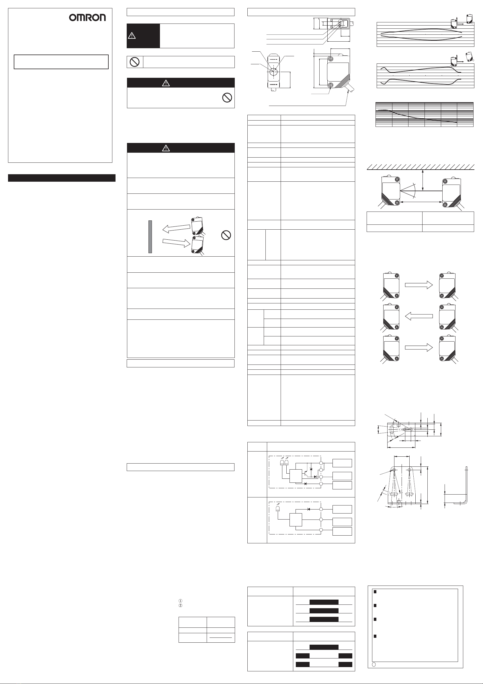
INFLUENCE OF MUTUAL INTERFERENCE
When installing two or more E3ZSs to each other, considerations must
be made to prevent mutual interference.
・Install so that any E3ZSs emit in the opposite directions (See below).
・
Install a light interrupting wall in between sensors.
・Install the E3ZSs facing away from the one another to
eliminate mutual interference.
Note : When using multiple sets of E3ZSs, be sure to
confirm that mutual interference is not occurred.
Emitter
Receiver
Emitter
Receiver
Emitter
Receiver
10゚
14゚
2-
φ
3
5.8
3.4
4.5
6
13.7
1.2
R20
29
3.4
8.8
3.2
R25.4
39
1.2 3.5
16±0.1
■ENGINEERING DATA
200
150
100
50
0
-50
-100
-150
-200
Sensing Range
Y Operating Range [mm]
X Detection distance [m]
0123456
Y Mutual interference range [mm]
100
10
1
0.1
Excess Gain Ration
Excess gain ration
Distance [m]
024681012
Receiver
Emitter
Y
X
200
150
100
50
0
-50
-100
-150
-200
0123456
X Detection distance [m]
Mutual Interference Range
Receiver
Emitter
YX
SUITABILITY FOR USE
1. Read this instruction sheet thoroughly to understand before using the
product.
2. When used in combination with the F3SX safety controller, make
sure that the B1 module is properly connected.
3. A load must not be shorted. A load must not be used with current
higher than the rating. Do not apply the reversed supplied voltage.
Be sure to route the E3ZS cable separated from high-potential power
line or through an exclusive conduit.
4. Do not remove the label (yellow) from the sensor. Doing so may
violate the specifications.
5. Wire the cable so that it has some slack and does not prevent
personnel or object passage.
Allow some leeway for the wires and do not tight the wires when
connection cable to F3SX, and confirm that any cable may not block
the movements of workers or objects.
6. Do not disassemble, repair or modify the E3ZS.
7. Be sure to dispose of the E3ZS as industrial waste.
Precautions for Safe Use
●Alert Statements
WARNING
When the single beam safety sensor model E3ZS is used as a
safety device or a part of safety systems for ensuring safety of
personnel, be sure to use it with the safety controller model F3SX
series.
WARNING
If the mode selection input line of the receiver is connected to 0V,
the output turns ON when light is interrupted (Dark ON), which no
longer configures the safety system. Be sure to connect the mode
selection input line to 24V DC to make the sensor output ON when
light is incident (Light ON).
Always maintain a safe distance between the E3ZS and a
hazardous part of a machine. Be sure to refer to the related
standards (EN999) for the calculation of safety distance.
Use an opaque test rod with 18mm in diameter and 200mm or
greater in effective length to check the detection capability. The
E3ZS cannot detect transparent materials.
Do not use the E3ZS in a reflective configuration, otherwise
detection may fail.
Do not install the E3ZS in a location where it can be affected by
wall reflections to avoid detection failure, which may result in
serious injury.
When using multiple sets of E3ZS, arrange them to prevent mutual
interference. Failure to do so may cause the sensor not to detect,
resulting in serious injury.
The E3ZS does not offer protection to the operator’s body from
projectiles existing the hazardous area. Proper means of
mechanical guarding must be provided to ensure protection from
these potentially hazardous projectiles.
Wiring must be done while the power is turned OFF. Doing it with
the power ON may cause an electric shock.
Do not connect the E3ZS to an AC or DC power supply with higher
voltage than nominal DC24V. Otherwise the sensor may explode,
burn, or cause electric shock. The power supply must conform to
regulatory requirements and standards, regarding EMC and
electrical equipment safety, of the country where the E3ZS is
installed. For example, the power supply must fulfill EN60742
requirements for double insulation and must conform to EMC
Directive and Low Voltage Directive in EU.
Emitter
Receiver
Reflective
Panel
DIMENSIONS
Optical
axis
6.7dia
25.4
2.1
15.5
8
20
10.8
10.4
3.54
17
31
Lens
Vinyl insulated round cord
4dia, Emitter:3core, Receiver:4core
length 2m
Light emittion indicator(Emitter only)
Stability indicator(Receiver only)
Operation indicator(Receiver only)
2-M3
■RATINGS / PERFORMANCE
Through beam type
100ms
( )
( )
12 to 24V DC±10% (ripple p-p 10% max)
1.0ms (E3ZS only)
Response time depends on the F3SX.
For the details, see the users manual of the F3SX.
( )
22.5 to 24V DC : Emitting OFF
(Source current : 3mA max)
Open or 0 to 2.5 V DC : Emitting ON
(Leakage current : 0.1mA max)
When the E3ZS is used as a part of safe
apparatus or safe systems Category2(EN954-1),
use it with F3SX.
( )
Transistor output PNP, load current 100mA max
Output residual voltage of 1V or less
(when load current is less than 10mA)
Output residual voltage of 2V or less
(when load current is from 10 to 100mA)
(except for voltage drop due to cable extension)
When the E3ZS is used as a part of safe
apparatus or safe systems Category2(EN954-1),
use it with F3SX.
E3ZS
Illumination intensity
Incandescent lamp : 3000 lx max.
Sunlight : 10000 lx max.
Operating : -10〜55℃, Storage : -10〜70℃
(not freezing or condensation)
Operating : 35〜85% RH, Storage : 35〜95% RH
(not freezing or condensation)
Emitter : Orange / Light emission
Receiver : Green / Stability, Orange / Operation
Durability
Operation limit
Durability
Operation limit
When using E3ZS by itself:
EN954-1 (Category 1)
IEC60947-5-3 (PDF-D)
UL508
When E3ZS is connected to F3SX:
IEC61496-1 Type2 ESPE
IEC61496-2 Type2 AOPD
EN954-1 (Category 2)
UL508
UL61496-1 Type2 ESPE
UL61496-2 Type2 AOPD
・Instruction sheet
Model F3SX series
±5°(at 3m)
Emitter : 15mA max.
Receiver : 20mA max.
0.2~3m
Opaque object of
φ
18mm or more.
When the E3ZS is used as a part of safe
apparatus or safe systems Category2(EN954-1),
use it with F3SX.
Detection method
Controller
Power supply voltage
Operating angle
Current consumption
Sensing distance
Standard object
Response time
Control output
Power reset time
DC-13 (Control of electromagnets)
Utilization categories
for switching elements
Ambient illumination
Ambient temperature
Ambient humidity
Insulation resistance
Dielectric strength voltage
Enclosure ratings
Light source
Indicators
Circuit protection
Weight
Applicable
standards
Accessories
Vibration
resistance
Shock
resistance
Test Input
(Emitter)
20MΩor more (by 500V DC megger)
1000V AC, 50/60Hz for 1 min.
10〜55 Hz, 1.5mm double amplitude,
each X, Y, Z direction , 2 hours
10〜55 Hz, 0.7mm double amplitude,
each X, Y, Z direction , 50 min.
500m/s2(approx. 50G),
each X, Y, Z direction for 3 times
100m/s2(approx.10G),
each X, Y, Z direction for 1,000 times
IEC standard IP67
Red LED
Output short-circuit and power supply reverse polarity
Approx. 120g (1set)
■CIRCUIT DIAGRAM
●PNP output
Output mode : ON when incident (Light ON)
Output / Input circuit
Main
circuit
Stability
indicator
OrangeGreen
Operation
indicator
Connect to
24V DC terminal
Connect to cont
output terminal
Connect to 0V
terminal
(Note 1)
Brown
Brown
Pink
Pink
Black
Blue
Blue
(Note 1)
(Note 2)
(Note 1)
Main
circuit
Connect to
24V DC terminal
Connect to test
input terminal
Connect to 0V
terminal
(Note 1)
(Note 1)
(Note 3)
(Note 1)
(Note 1)・When the E3ZS is used as a part of safe apparatus or safe
systems Category2(EN954-1), connect to the B1 module of the
F3SX. Do not connect to the other modules.
・For the details, see the users manual of the F3SX.
(Note 2)・
Be sure to connect the ''Mode selection input'' to 24V DC terminal.
(Note 3)・When the E3ZS is used without being connected to F3SX, test
input should be connected to 0V.
Receiver
Emitter
Light emittion
indicator
■INFLUENCE OF REFLECTIVE SURFACES
Install the E3ZS with minimum distance D (given below) away from
reflective surfaces (highly reflective surfaces) such as metal walls, floors,
ceilings, and work pieces
Reflective Surfaces
5°
5°
D
L
Distance between emitter and
receiver
( Operating range L )
0.2 to 3 m
Minimum installation
distance D
0.27 m or more
No-load voltage
(V peak)
0 to 20
More than 20,
up to 30
Maximum current rating
(A)
5.0
100
Peak voltage value
1.Do not install the E3ZS in the following environments:
・Areas exposed to intense interference light, such as direct sunlight;
・Areas with high-humidity where condensation is likely to occur;
・Areas exposed to corrosive, flammable or explosive gases;
・Areas in the presence of substances, such as heavy smoke or
particulate matter, that may deteriorate product quality;
・Areas exposed to vibration or shock levels higher than specification
provisions;
・Areas where the product may come in direct contact with water, oil,
and chemicals;
2. Do not install the E3ZS in water.
3. To extend the cable, use a wire of cross-sectional area 0.3mm2or
more. However do not extend it more than 100m.
4. Be careful not to exceed a tightening torque of 0.5 Nm. Also, if it is
not tight enough, vibration may cause it to come loose.
5. When cleaning, avoid using thinner, benzene or acetone.
6. Power supply specifications
For combined DC power supply, use the following UL certified
products:
(1) Limited voltage current circuit that conforms to UL508
Circuit with a power supply that consists of a secondary coil of
an insulated transformer that satisfies the following conditions:
-
Maximum voltage(with no load)
: 30Vrms (42.4V peak) or less, and
-Maximum current :
8A or less (including short-circuit), or
When limited by a circuit
protector (fuse, etc.) with the
ratings shown in the table below
(2) Class 2 power supply unit that conforms to UL1310
(3) Circuit (class 2 circuit) with 30Vrms (42.4V peak) or less of
maximum voltage, and which uses a class 2 transformer that
conforms to UL1585 as its power supply
Precautions for Correct Use
●Meanings of Signal Words
Indicates a potentially hazardous
situation which, if not avoided, will
result in minor or moderate injury, or
may result in serious injury or death.
Additionally there may be significant
property damage.
WARNING
●Meanings of Alert Symbols
Indicates prohibited actions.
Precautions on Safety
・When the E3ZS is used with the F3SX, the requirements of the
Category 2 (EN954-1) are satisfied.
・When the E3ZS is used without the F3SX, it corresponds to the
Category 1 (EN954-1).
・Read the F3SX users manual (SCHG-705) about the rating or other
specifications of the F3SX.
TRACEABILITY INFORMATION:
Representative in EU:
Omron Europe B.V.
Wegalaan 67-69
2132 JD Hoofddorp,
The Netherlands
Manufacturer:
Omron Corporation,
Shiokoji Horikawa, Shimogyo-ku,
Kyoto 600-8530 JAPAN
Shanghai Factory
No.789 Jinji Road,
Jinqiao Export Processing District,
Pudong New Area,Shanghai,201206 CHINA
INSTRUCTION SHEET
Thank you for selecting OMRON product.This sheet pri-
marily describes precautions required in installing and
operating the product.
Before operating the product,read the sheet thoroughly to
acquire sufficient knowledge of the product.For your con-
venience,keep the sheet at your disposal.
The following notice applies only to products that carry the CE mark:
Notice:
This is a class A product. In residential areas it may cause radio
interference, in which case the user may be required to take adequate
measures to reduce interference.
OMRON Corporation
EUROPE
OMRON EUROPE B.V. Sensor Business Unit
Carl-Benz Str.4, D-71154 Nufringen Germany
Phone:49-7032-811-0 Fax: 49-7032-811-199
NORTH AMERICA
OMRON ELECTRONICS LLC
One Commerce Drive Schaumburg,IL 60173-5302 U.S.A.
Phone:1-847-843-7900 Fax : 1-847-843-7787
ASIA-PACIFIC
OMRON ASIA PACIFIC PTE. LTD.
No. 438A Alexandra Road #05-05-08(Lobby 2),
Alexandra Technopark, Singapore 119967
Phone : 65-6835-3011 Fax :65-6835-2711
o
CHINA
OMRON(CHINA) CO., LTD.
Room 2211, Bank of China Tower,
200 Yin Cheng Zhong Road,
PuDong New Area, Shanghai, 200120, China
Phone : 86-21-5037-2222 Fax :86-21-5037-2200
OCT, 2009


