Omron E2C-EDA Series User manual

High-resolution Digital Proximity Sensor with Separate Amplifier
E2C-EDA Series
A Digital Proximity Sensor At Last!A Digital Proximity Sensor At Last!A Digital Proximity Sensor At Last!
otice.
pe
ct

Industry First
2
Finally a Digital Proximity Sensor Capable of
High-resolution Sensing with Unprecedented Ease
Sensors
Sensors
An Array of Heads Flexible Cables Provided as a Standard Feature
Industry Leader
High-resolution Sensing Unaffected by Environmental Swings
Excellent temperature characteristics at 0.08%/°C (5.4-mm dia. Sensor Head)
Flat 3 dia. 5.4 dia. 8 dia. M10 M18
Heat resistant
to 200°C
0.55
0.50
0.45
−20 0 20 40 60
Sensing distance (mm)
Ambient Sensor Head temperature (˚C)
Temperature Influence (Typical Examples)
5.4-mm dia. E2C-ED01(-@)
Flexible cable
Connector
May be cut any length up to 3 m
(models ending in -F)
An Impressive Lineup of Sensor Heads to Handle a Wide Variety of Applications
The lineup includes some Sensor Heads as thin
as 3-mm in diameter and others that are thin and
flat. Narrow installation spaces are not a problem
for these models. Still other Sensor Heads are
heat resistant or rated IP67 for superior
environmental resistance. These models are
capable of high-resolution sensing even in harsh
environments.
With flexible cables connecting the Preamplifier to the
Amplifier, installation on moving parts is never a problem.
The twin-output models can also output an open-circuit
alarm. In that rare instance where the cable breaks, the
E2C-EDA can then send out an alarm that greatly simplifies
the task of locating the faulty Sensor.
In addition to repeat accuracy of 1-µm or better, the
temperature characteristics of the E2C-EDA are flat.
This means that environmental factors, such as
temperature swings in the morning and at night, will
not affect high-resolution positioning and screening.

ustry First
Industry First
Patent pending
3
High-resolution Digital Proximity Sensor
with Separate Amplifier
E2C-EDA Series
Amplifiers
Amplifiers
Simple and Reliable Measurements with Micron-level Resolution
Two Clear, Large, and Easy-to-Read Digital Displays
Fine Positioning Maximizes Digital Changes
Digital Display Simplifies Installation and Settings
Connector for Connecting
Sensor Heads to Amplifiers
Leader
Execute Fine
Positioning
at 0.5 mm.
Sensing Distance - Digital Value Characteristic (Typical)
5.4-mm dia. E2C-ED01(-@)
4000
3000
2000
1000
0 0.5 1.0 1.5 2.0
Display value (digital value)
Sensing distance (mm)
4000
3000
2000
1500
1000
0 0.5 1.0 1.5 2.0
Display value (digital value)
Sensing distance (mm)
Note 1: Press the MODE Key with the E3C-EDA running to switch to individual teaching modes,
Fine Positioning, or Zero Reset.
Character size: 6 mm
Detected value Threshold value
Threshold Teaching
MODE Key
(See note 1.)
UP/DOWN Keys
for fine threshold value adjustments
Display reads 1,500 when Fine Positioning
is executed.
The E2C-EDA features two large, easy-to-read digital
displays. Since the digitized detected and threshold values
can be checked at the same time, settings are simple and
reliable for just about anyone. Various teaching methods are
also available for settings that cannot be made consistently
by different operators.
In the stable sensing zone, the E2C-EDA generally
reads 1,500 or higher (see note 2). This way you can tell
at a glance whether the current installation and settings
are within the optimal range.
Note 2: This reading is only a guideline because there may be some variation
between Sensors. Also refer to the Engineering Data because values may
vary with non-standard objects.
A Shielded Connector is used for more
reliable wiring and easier cable handling.
Since the press-fit connector allows repeat
connections, wiring and head replacement
are simple and reliable.
Support for High-resolution Positioning and Screening
Fine Positioning maximizes changes in the digital value as you get closer to
the sensing point. More precise sensing can be achieved by executing Fine
Positioning with the workpiece positioned at the point to be maximized.

4
Smart Functions for High-resolution Parts and
Assembly Inspection Applications
Digital Display
Area Output (Twin-output Type)
Mutual Interference Prevention
The status is ambiguous
when dial positions are checked.
Conventional Dial Type Digital Type
Workpiece 1 Workpiece 2
The status is clear
from the digital display.
Workpiece 1
2500
Workpiece 2
1500
Digital value
3000
2000
Non-defective
product
Output between
threshold 1 and threshold 2.
Threshold 1
3000
Threshold 2
2000
Optical
communications
Five Sensors max.
Applications
Applications
Mixed bearing inspection
(material and height sensing)
Screening
Height inspection
Height inspection
Capacitor sleeve
mounting inspection
Screw assembly
inspection
The E2C-EDA can visually recognize height and
material differences simply and reliably even with the
most demanding settings.
An OK/NG result is easily obtained because the
E2C-EDA outputs a signal between two threshold
values.
The E2C-EDA has a mutual interference prevention
function that uses intermittent sensing via optical
communications to enable up to 5 Sensors to be
combined very closely together. This feature enables
multiple measurements to be made in a machine or
process.

OMRON's unique wiring-saving Connector
reduces the amount of wiring required even
with a mixture of different sensing types.
E3X-DA-S Digital Fiber Sensor
E3X-MDA Digital Fiber Sensor
(2-Amplifier Type)
E3C-LDA Laser-type Photoelectric Sensors
E2C-EDA Digital Proximity Sensor
5
Change in Machine Arrangement
Zero Reset
The origin (reference) is offset.
Correction completed!
Teaching
Zero Reset (Fixed Threshold)
Operator setting inconsistencies
Conventional dial type Digital type
Settings are simple enough
for anyone with teaching
(reduces operator setting
inconsistencies).
Perfect
Platform Concept Ensures Common Operation and Programming Devices
Positioning
Gap inspection
Press-fit inspection
(positioning)
Metal chip and
shaving buildup
inspection
for presses
High-resolution Digital Proximity Sensor
with Separate Amplifier
E2C-EDA Series
Position teaching yields consistent settings that cannot
be matched by operator settings.
When using a fixed sensing gap (threshold), the origin
and reference position can be corrected quite simply if
needed, such as when changing the process being
performed.
Simple and Common Sensor Operation in Devices
The basic functions and Programming Devices like the Mobile Console are the same for the
E2C-EDA as they are for the E3X-DA-S Digital Fiber Sensor and the E3C-LDA Laser-type
Photoelectric Sensor. Just select the right type of E2C-EDA for the application, and the rest is easy.

6E2C-EDA High-resolution Digital Proximity Sensor
Ordering Information
■Sensors
Sensor Heads
Note 1. A Protective Spiral Tube is provided with models ending in the suffix -S. (example: E2C-ED01-S).
2. Two cable lengths are available. (3-dia.: free-cut type, Heat-resistant type: standard-length only).
Overall length of the standard-length type: 2.5 m, Length from the Sensor Head to the Preamplifier: 2.0 m (Example: E2C-ED01)
Overall length of the free-cut type: 3.5 m, Length from the Sensor Head to the Preamplifier: 0.5 m for models ending in the suffix -F
(example: E2C-ED01F).
3. Models ending in the suffix -S that come with Protective Spiral Tubes and free-cut models ending in the suffix -F are made-to-order
products.
Amplifier Units
Amplifier Units with Cables
Type Appearance Sensing distance Repeat accuracy Model
Shielded 3 dia. ×18 mm 1 µm E2C-EDR6-F (See note 2.)
5.4 dia. ×18 mm 1 µm E2C-ED01-
@
(See notes 1, 2,
and 3.)
8 dia. ×22 mm 2 µm E2C-ED02-
@
(See notes 1, 2,
and 3.)
M10 ×22 mm 2 µm E2C-EM02-
@
(See notes 1, 2,
and 3.)
30 ×14 ×4.8 mm 2 µm E2C-EV05-
@
(See notes 1, 2,
and 3.)
Unshielded M18 ×46.3 mm 5 µm E2C-EM07M-
@
(See notes 1,
2, and 3.)
Heat-resistant M12 ×22 mm 2 µm E2C-EM02H (See note 2.)
Cylindrical
0.6 mm
1 mm
2 mm
Screw
2 mm
Flat
5 mm
Screw
7 mm
Screw
2 mm
Item Appearance Functions Model
NPN output PNP output
Advanced models Twin-output models Area output, open
circuit detection,
differential operation
E2C-EDA11 E2C-EDA41
External-input models Remote setting,
differential operation
E2C-EDA21 E2C-EDA51

E2C-EDA High-resolution Digital Proximity Sensor 7
Amplifier Units with Connectors
Amplifier Unit Connectors (Order Separately)
Mobile Console (Order Separately)
Note:Use the E3X-MC11-SV2 Mobile Console with E2C-EDA-series Amplifier Units. If you use a Mobile Console like the E3X-MC11-S, some
functions may not operate.
Item Appearance Functions Model
NPN output PNP output
Advanced models Twin-output models Area output, open
circuit detection,
differential operation
E2C-EDA6 E2C-EDA8
External-input models Remote setting,
differential operation
E2C-EDA7 E2C-EDA9
Item Appearance Cable length No. of conductors Model
Master Connector 2 m 4 E3X-CN21
Slave Connector 2 E3X-CN22
Connector Ordering Precaution
Amplifier Units and Connectors are sold separately.
Refer to the following tables when placing an order.
When Using 5 Amplifier Units
Amplifier Unit Applicable Connector (Order Separately)
Model NPN output PNP output Master Connector Slave Connector
Advanced models E2C-EDA6 E2C-EDA8 +E3X-CN21 E3X-CN22
E2C-EDA7 E2C-EDA9
Amplifier Units (5 Units) + 1 Master Connector 4 Slave Connectors
Appearance Model Remarks
E3X-MC11-SV2
(model number of set)
Mobile Console with
Head, Cable, and AC
adapter provided as
accessories
E3X-MC11-C1-SV2 Mobile Console
E3X-MC11-H1 Head
E39-Z12-1 Cable (1.5 m)

8E2C-EDA High-resolution Digital Proximity Sensor
Accessories (Order Separately)
Mounting Bracket
End Plate
Specifications
Sensor Heads
Note 1. The repeat accuracy and temperature characteristic are for a standard sensing object positioned midway through the rated sensing distance.
2. A sudden temperature rise even within the rated temperature range may degrade characteristics.
3. For the Sensor Head only without the preamplifier (−10 to 60°C). With no icing or condensation.
4. Do not operate in areas exposed to water vapor because the enclosure is not waterproof.
Appearance Model Quantity
E39-L143 1
Appearance Model Quantity
PFP-M 1
Model E2C-EDR6-F E2C-ED01(-@)E2C-ED02(-@)E2C-EM02-@)E2C-EM07(-@)E2C-EV05(-@)E2C-EM02H
Item 3 dia. ×18 mm 5.4 dia. ×18 mm 8 dia. ×22 mm M10 ×22 mm M18 ×46.3 mm 30 ×14 ×4.8 mm M12 ×22 mm
Sensing distance 0.6 mm 1 mm 2 mm 7 mm 5 mm 2 mm
Sensing object Magnetic metal (The sensing distance will decrease when sensing non-magnetic metal. Refer to Engineering
Data on page 10.)
Standard sensing object 5 ×5 ×3 mm 10 ×10 ×3 mm 22 ×22 ×3 mm 15 ×15 ×3 mm 20 ×20 ×3 mm
Material: iron (S50C)
Repeat accuracy
(See note 1.)
1 µm2µm5µm2µm
Hysteresis distance Variable
Tempera-
ture char-
acteristic
(See note
1.)
Sensor Head 0.3%/°C 0.08%/°C 0.04%/°C0.2%/°C
Preamplifier and
Amplifier
0.08%/°C
Ambient
tempera-
ture (See
note 2.)
Operating –10°C to 60°C (with no icing or condensation) –10°C to
200°C
(See note 3.)
Storage –10°C to 60°C
(with no icing
or
condensation)
–20°C to 70°C (with no icing or condensation)
Ambient humidity Operating/storage: 35% to 85% (with no condensation)
Insulation resistance 50 MΩmin. (at 500 VDC)
Dielectric strength 1,000 VAC at 50/60 Hz for 1 min between current carry parts and case
Vibration resistance Destruction: 10 to 55 Hz, 1.5-mm double amplitude for 2 hours each in X, Y, and Z directions
Shock resistance Destruction: 500 m/s2for 3 times each in X, Y, and Z directions
Degree of protection IEC60529 IP67 IEC60529
IP60
(See note 4.)
Connection method Connector (standard cable length: 2.5 m (2 m between Head and Preamplifier)
“-F” model cable length: 3.5 m (0.5 m between Head and Preamplifier)
Weight (packed state) Approx. 120 g (Models with protective spiral tube (“-S” models) are approx. 90 g heavier.)
Material Sensor
Head
Case Brass Stainless steel Brass Zinc Brass
Sensing
surface
Heat-resistant ABS PEEK
Clamp-
ing nut
--- Nickel-plated brass --- Nickel-plated
brass
Toothed
washer
--- Zinc-plated iron --- Zinc-plated
iron
Preamplifier PES
Accessories Preamplifier Mounting Brackets, Instruction Manual

E2C-EDA High-resolution Digital Proximity Sensor 9
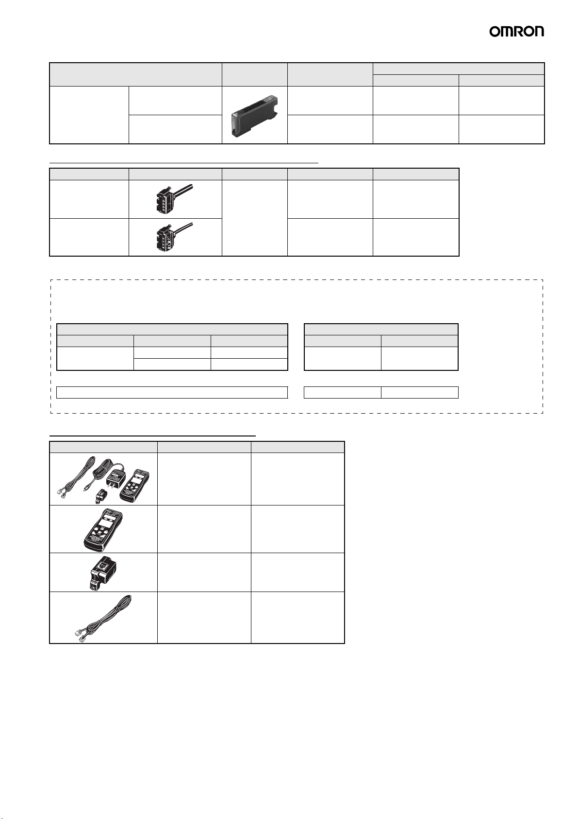
Amplifier Units
Note:Communications are disabled if the detection mode is selected during super-high-speed sensing mode, and the communications functions
for mutual interference prevention and the Mobile Console will not function.
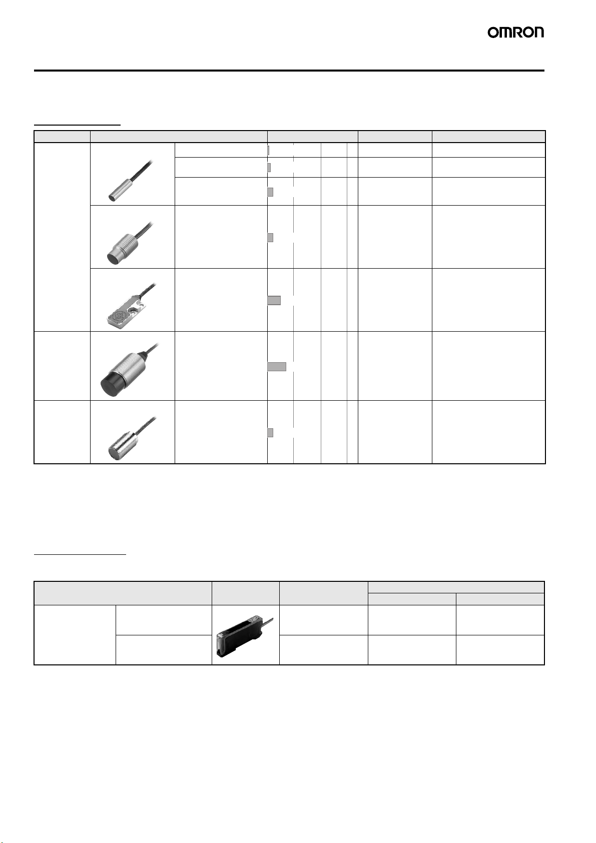
Type Advanced Models with Twin Outputs Advanced Models with External Inputs
Model NPN output E2C-EDA11 E2C-EDA6 E2C-EDA21 E2C-EDA7
Item PNP output E2C-EDA41 E2C-EDA8 E2C-EDA51 E2C-EDA9
Supply voltage 12 to 24 VDC ±10%, ripple (p-p): 10% max.
Power consumption 1,080 mW max. (current consumption: 45 mA at power supply voltage of 24 VDC)
Control output Load power supply voltage: 26.4 VDC max.; NPN/PNP open collector output; load current: 50 mA max.
(residual voltage: 1 V max.)
Response time Super-high-
speed mode
150 µs for operation and reset respectively
High-speed
mode
300 µs for operation and reset respectively
Standard mode 1 ms for operation and reset respectively
High-
resolution
mode
4 ms for operation and reset respectively
Functions Differential de-
tection
Switchable between single edge and double edge detection mode
Single edge: Can be set to 300 µs, 500 µs, 1 ms, 10 ms, or 100 ms
Double edge: Can be set to 500 µs, 1 ms, 2 ms, 20 ms, or 200 ms.
Timer function Select from OFF-delay, ON-delay, or one-shot timer.
1 ms to 5 s (1 to 20 ms set in 1-ms increments, 20 to 200 ms set in 10-ms increments,
200 ms to 1 s set in 100-ms increments, and 1 to 5 s set in 1 s-increments)
Zero-reset Negative values can be displayed. (Threshold is not shifted.)
Initial reset Settings can be returned to defaults as required.
Mutual interfer-
ence preven-
tion
Possible for up to 5 Units. (See note.)
Intermittent oscillation method (Response time = (number of Units connected + 1) ×15 ms)
Hysteresis set-
tings
Setting range: 10 to 4,000
I/O settings Output setting (Select from channel 2 output, area
output, self-diagnosis, or open circuit detection.)
Input setting (Select from teaching, fine positioning,
zero-reset, synchronous detection.)
Digital display Select from the following: Incident level + threshold, incident level percentage +threshold, incident light peak
level + incident light bottom level (updated with output), long bar display, incident level + peak hold, incident
level + channel
Display orientation Switching between normal/reversed display is possible.
Ambient temperature Operating:
When connecting 1 to 2 Units: –10°C to 55°C
When connecting 3 to 5 Units: –10°C to 50°C
When connecting 6 to 16 Units: –10°C to 45°C
When used in combination with an EDR6-F
When connecting 3 to 4 Units: –10°C to 50°C
When connecting 5 to 8 Units: –10°C to 45°C
When connecting 9 to 16 Units: –10°C to 40°C
Storage: –20°C to 70°C (with no icing)
Ambient humidity Operating/storage: 35% to 85% (with no condensation)
Insulation resistance 20 MΩmin. (at 500 VDC)
Dielectric strength 1,000 VAC at 50/60 Hz for 1 min
Vibration resistance Destruction: 10 to 55 Hz, 1.5-mm double amplitude for 2 hours each in X, Y, and Z directions
Shock resistance Destruction: 500 m/s2for 3 times each in X, Y, and Z directions
Degree of protection IEC60529 IP50
Connection method Prewired Connector Prewired Connector
Weight (packed state) Approx. 100 g Approx. 55 g Approx. 100 g Approx. 55 g
Material Case PBT (polybutylene terephthalate)
Cover Polycarbonate

10 E2C-EDA High-resolution Digital Proximity Sensor
Engineering Data
Sensing Distance vs. Display Values
E2C-EDR6-F E2C-ED01(-@) E2C-ED02(-@)/EM02(-@)
E2C-EM07(-@) E2C-EV05(-@) E2C-EM02H
4000
3000
2000
1500
1000
0 0.3 0.6 0.9 1.
2
Display value (Digital value)
Sensing distance (mm)
Fine
positioning
at 0.9 mm
Fine
positioning
at 0.3 mm
4000
3000
2000
1500
1000
0 0.5 1.0 1.5 2.
0
Display value (Digital value)
Sensing distance (mm)
Fine
positioning
at 1.5 mm
Fine
positioning
at 0.5 mm
4000
3000
2000
1500
1000
0 1 2 3 4
Display value (Digital value)
Sensing distance (mm)
Fine
positioning
at 3 mm
Fine
positioning
at 1 mm
4000
3000
2000
1500
1000
0 3.5 7.0 10.5 1
4
Display value (Digital value)
Sensing distance (mm)
Fine
positioning
at 10.5 mm
Fine
positioning
at 3.5 mm
4000
3000
2000
1500
1000
0 2.5 5 7.5 1
0
Display value (Digital value)
Sensing distance (mm)
Fine
positioning
at 7.5 mm
Fine
positioning
at 2.5 mm
4000
3000
2000
1500
1000
0 1 2 3 4
Display value (Digital value)
Sensing distance (mm)
Fine
positioning
at 3 mm
Fine
positioning
at 1 mm

E2C-EDA High-resolution Digital Proximity Sensor 11
Influence of Sensing Object Size and
Material
E2C-EDR6-F E2C-ED01(-@) E2C-ED02(-@)/EM02(-@)
E2C-EM07(-@) E2C-EV05(-@) E2C-EM02H
1.2
1.0
0.8
0.6
0.4
0.2
0 10 20 30 40 50
Sensing distance X (mm)
Len
g
th of sensed ob
j
ect d
(
mm
)
Iron
Stainless
Aluminium
@d
t=3
mm
X
2.0
1.5
1.0
0.5
0 10 20 30 40 50
@d
t=3
mm
X
Sensing distance X (mm)
Len
g
th of sensed ob
j
ect d
(
mm
)
Iron
Stainless
Aluminium
4
3
2
1
0 10 20 30 40 50
@d
t=3
mm
X
Sensing distance X (mm)
Len
g
th of sensed ob
j
ect d
(
mm
)
Iron
Stainless
Aluminium
@d
t=3
mm
X
12
10
8
6
4
2
0 10 20 30 40 50
Sensing distance X (mm)
Len
g
th of sensed ob
j
ect d
(
mm
)
Iron
Stainless
Aluminium
@d
t=3
mm
X
10
8
6
4
2
0 10 20 30 40 50
Sensing distance X (mm)
Len
g
th of sensed object d (mm)
Iron
Stainless
Aluminium
@d
t=3
mm
X
4
3
2
1
0 10 20 30 40 50
Sensing distance X (mm)
Len
g
th of sensed ob
j
ect d
(
mm
)
Iron
Stainless
Aluminium

12 E2C-EDA High-resolution Digital Proximity Sensor
Influence of Sensor Head Temperature
E2C-EDR6-F E2C-ED01(-@) E2C-ED02(-@)/EM02(-@)
E2C-EM07(-@) E2C-EV05(-@) E2C-EM02H
0.35
0.30
0.25
−20 0 20 40 60
Sensing distance (mm)
Ambient temperature of Sensor Head (˚C)
0.55
0.50
0.45
−20 0 20 40 60
Sensing distance (mm)
Ambient temperature of Sensor Head (˚C)
1.1
1.0
0.9
−20 0 20 40 60
Sensing distance (mm)
Ambient temperature of Sensor Head (˚C)
4.0
3.5
3.0
−20 0 20 40 60
Sensing distance (mm)
Ambient temperature of Sensor Head (˚C)
2.7
2.5
2.3
−20 0 20 40 60
Sensing distance (mm)
Ambient temperature of Sensor Head (˚C)
1.1
1.0
0.9
−50 0 50 100 150 200
Sensing distance (mm)
Ambient temperature of Sensor Head (˚C)

E2C-EDA High-resolution Digital Proximity Sensor 13
Operation
NPN Output
Note 1. Setting Areas for Twin-output Models
Normally open: ON between the thresholds for Channel 1 and Channel 2
Normally closed: OFF between the thresholds for Channel 1 and Channel 2
2. Timing Charts for Timer Settings (T: Set Time)
Model Operation
mode
Timing chart Mode
selector
Output circuit
E2C-EDA11
E2C-EDA6
NO (Normally
open)
NO
NC (Normally
closed)
NC
E2C-EDA21
E2C-EDA7
NO (Normally
open)
NO
NC (Normally
closed)
NC
ON delay OFF delay One shot
Yes
No
Lit
Not lit
ON
OFF
Operate
Reset
Operation
indicator
(orange)
(Between brown and black lines)
Output
transistor
Load
(relay, etc.)
Sensing
object
Operation indicator
(orange) ch2
Control output
ch1
Control output
ch2
Orange 12 to 2
4
VDC
Operation indicator
(orange) ch1
Display
Load
Load
Brown
Black
Blue
Proximity
Sensor
main
circuits
Y
es
No
Lit
Not lit
ON
OFF
Operate
Reset
Operation
indicator
(orange)
(Between brown and black lines)
Output
transistor
Load
(relay, etc.)
Sensing
object
Yes
No
Lit
Not lit
ON
OFF
Operate
Reset
Operation
indicator
(orange)
(Between brown and black lines)
Output
transistor
Load
(relay, etc.)
Sensing
object
Control output
External
input
Orange
12 to 2
4
VDC
Operation
indicator (orange)
Display
Fine positioning
indicator
(orange)
Load
Brown
Black
Blue
Proximity
Sensor
main
circuits
Y
es
No
Lit
Not lit
ON
OFF
Operate
Reset
Operation
indicator
(orange)
(Between brown and black lines)
Output
transistor
Load
(relay, etc.)
Sensing
object
Yes
No
ON
OFF
ON
OFF
NO
NC
T
T
Sensing
object
Yes
No
ON
OFF
ON
OFF
NO
NC
T
T
Sensing
object
Yes
No
ON
OFF
ON
OFF
NO
NC
T
T
Sensing
object

14 E2C-EDA High-resolution Digital Proximity Sensor
PNP Output
Note 1. Setting Areas for Twin-output Models
Normally open: ON between the thresholds for Channel 1 and Channel 2
Normally closed: OFF between the thresholds for Channel 1 and Channel 2
2. Timing Charts for Timer Settings (T: Set Time)
Nomenclature
Amplifier Units
Twin-output Models
(E2C-EDA11/EDA41/EDA6/EDA8)
External-input Models
(E2C-EDA21/EDA51/EDA7/EDA9)
Model Operation mode Timing chart Mode
selector
Output circuit
E2C-EDA41
E2C-EDA8
NO (Normally
open)
NO
NC (Normally
closed)
NC
E2C-EDA51
E2C-EDA9
NO (Normally
open)
NO
NC (Normally
closed)
NC
ON delay OFF delay One shot
Yes
No
Lit
Not lit
ON
OFF
Operate
Reset
Operation
indicator
(orange)
(Between blue and black lines)
Output
transistor
Load
(relay, etc.)
Sensing
object
Orange Load
Load
Brown
Black
Blue
Proximity
Sensor
main
circuits
Operation indicator
(orange) ch2
Control
output ch1
Control
output ch2
12 to 2
4
VDC
Operation indicator
(orange) ch1
Display
Y
es
No
Lit
Not lit
ON
OFF
Operate
Reset
Operation
indicator
(orange)
(Between blue and black lines)
Output
transistor
Load
(relay, etc.)
Sensing
object
Yes
No
Lit
Not lit
ON
OFF
Operate
Reset
Operation
indicator
(orange)
(Between blue and black lines)
Output
transistor
Load
(relay, etc.)
Sensing
object
Load
Brown
Black
Blue
Proximity
Sensor
main
circuits
Control output
External
input
12 to 2
4
VDC
Operation
indicator (orange)
Display
Fine positioning
indicator
(orange)
Orange
Y
es
No
Lit
Not lit
ON
OFF
Operate
Reset
Operation
indicator
(orange)
(Between blue and black lines)
Output
transistor
Load
(relay, etc.)
Sensing
object
Yes
No
ON
OFF
ON
OFF
NO
NC
T
T
Sensing
object
Yes
No
ON
OFF
ON
OFF
NO
NC
T
T
Sensing
object
Yes
No
ON
OFF
ON
OFF
NO
NC
T
T
Sensing
object
Displays the incident light level
or the function name.
Displays the threshold values
and function settings.
Function setting operations
UP
DOWN
MODE
Used to select the channel to
display or set.
Used to select SET or RUN mode.
ON when output is ON.
OFF when out
p
ut is OFF.
ON when output is ON.
OFF when output is OFF.
Operation Indicator
for Channel 1 (Orange)
Main Display (Red) Sub-Display (Green) Operation Keys
Channel Selector
SET/RUN Mode Selector
Operation Indicator
for Channel 2 (Orange)
UP
DOWN
MODE
Used to select normally open
or normally closed.
Fine positioning setting
Operating Mode Selector
Fine Positioning Indicator
(Orange)
Displays the incident light level
or the function name.
Displays the threshold values
and function settings. Function setting operations
Used to select SET or RUN mode.
ON when output is ON.
OFF when output is OFF.
Operation Indicator
(Orange)
Main Display (Red) Sub-Display (Green) Operation Keys
SET/RUN Mode Selector

E2C-EDA High-resolution Digital Proximity Sensor 15
Precautions
!WARNING
Precautions for Correct Use
Do not use this product in operating atmospheres or environments
outside the specified ratings.
Amplifier Units
●Design
Power ON
The Sensor is ready to sense an object within 200 ms after turning
the power ON. If the load and Sensor are connected to different
power supplies, always turn ON the Sensor power first.
●Connecting Sensor Heads
Connecting and Disconnecting Sensor Heads
1. Open the protective cover.
2. Making sure that the lock button is up, insert the fibers all the way
to the back of the Connector insertion opening.
To disconnect the Sensor Head, pull out the fibers while pressing on
the lock button.
Connecting and Disconnecting Connectors
Connecting Connectors
1. Insert the Master or Slave Connector into the Amplifier Unit until it
clicks into place.
2. Apply the supplied seal to the non-connection surface of the Mas-
ter/Slave Connector.
Note: Apply the seal to the grooved side.
Disconnecting Connectors
1. Slide the Slave Amplifier Unit.
2. After the Amplifier Unit has been separated, press down on the
lever on the Connector and remove it. (Do not attempt to remove
Connectors without separating them from other Amplifier Units
first.)
Installing and Removing Amplifier Units
Installing Amplifier Units
1. Install the Units one by one to the DIN rail.
2. Slide one Unit toward the other, match the clips at the front ends,
and then bring them together until they “click.”
Removing Amplifier Units
Slide one Unit away from the other and remove them one by one.
(Do not remove the connected Units together from the DIN rail.)
End Plate Mounting (PFP-M)
Mount End Plates on Amplifier Units to avoid movement due to
vibration. When a Mobile Console is installed, mount the End Plate
facing as shown in the following diagram.
Do not use this product in any safety device used for the
protection of human lives.
1
2
Lock button
Insert
Protector seal
Power supply Connector
Note 1. When the Amplifier Units are connected to each other, the
operable ambient temperature changes depending on the
number of connected Amplifier Units. Check Specifications.
2. Before connecting or disconnecting the Units, always switch
power OFF.
Remove
Lever
Press down.
Sensor Head Connector Clips
DIN rail
1
2
DIN rail
1
1
2
End Plate

16 E2C-EDA High-resolution Digital Proximity Sensor
Mounting a Communications Head for the Mobile
Console
Leave a space of at least 20 mm on the left side of the Units for a
Mobile Console Communications Head.
EEPROM Write Error
If the data is not written to the EEPROM correctly due to a power
failure or static-electric noise, initialize the settings using the keys on
the Amplifier Unit.
Optical Communications
When using more than one Amplifier Unit, mount the Units side-by-
side. Do not slide or remove Units while they are in use.
●Miscellaneous
Protective Cover
Be sure to put on the Protective Cover before use.
Mobile Console
Use the E3X-MC11-SV2 Mobile Console for E2C-EDA-series
Amplifier Units. Other Mobile Consoles, such as the E3X-MC11,
cannot be used.
Sensor Head and Amplifier Unit Connection
Be sure to use only specified Sensor Head and Amplifier Unit
combinations. The E3C-LDA-series Photoelectric Sensor with
Separate Digital Amplifier is not compatible, and the E2C-EDA must
not be used with products from that series.
Warm-up
The digital display will slowly change until the circuits stabilize after
the power is turned ON. It takes about 30 minutes after the power is
turned ON before the E2C-EDA is ready to sense.
Maintenance Inspection
•Be sure to turn OFF the power before adjusting, connecting, or
disconnecting the Sensor Head.
•Do not use thinner, benzene, acetone, or kerosene to clean the
Sensor Head or Amplifier Unit.
Sensor Heads
●Mounting
Mounting Sensor Heads
•Use the dimensions from the following table to mount unthreaded
cylindrical models (E2C-ED-@@). Do not tighten screws with
torque exceeding 0.2 N·m when mounting Sensor Heads.
•Use the torque given in the following table to tighten threaded
cylindrical models (E2C-EM@@).
•Do not use torque exceeding 0.5 N·m to tighten screws when
mounting flat models (E2C-EV@@).
•Use a bending radius of at least 8 mm for the Sensor Head cable.
•Use only the special extension cable to extend the cable between
the Sensor Head and the Amplifier Unit. Consult your OMRON
representative for details.
Effects of Surrounding Metal
•Provide a minimum distance between the Sensor and the
surrounding metal as shown in the table below.
Effects of Surrounding Metal (Units: mm)
Mutual Interference
•If more than one Sensor Head is installed face to face or in parallel,
make sure that the distances between two Units adjacent to each
other are the same as or larger than the corresponding values
shown in the following table.
•The distance between Sensor Heads may be narrower than
specified with these Sensors because the Mutual Interference
Prevention Function is used for optical communications between
the Amplifier Units.
Mutual Interference (Units: mm)
20 mm
Model Tightening range A
E2C-EDR6-F 9 to 18 mm
E2C-ED01@@ 9 to 18 mm
E2C-ED02@@ 11 to 12 mm
Dimpled end of
set screw
E2C-ED@@
Model Tightening torque
E2C-EM02@@ 15 N·m max.
E2C-EM07M@@ 15 N·m max.
E2C-EM02H@@ 5.9 N·m max.
Model Face-to-
face
arrange-
ment A
Parallel
arrange-
ment B
Face-to-face
arrangement
using the
Mutual
Interference
Prevention
Function A'
Parallel
arrangement
using the
Mutual
Interference
Prevention
Function B'
E2C-EDR6-F 14 10 3.5 3.1
E2C-ED01@@ 45 20 9 5.4
E2C-ED02@@ 35 30 21 8
E2C-EM02@@ 36 30 21 10
E2C-EM07M@@ 140 120 35 18
E2C-EV05@@ 65 30 21 14
E2C-EM02H@@ 45 30 21 12
Model Counterbore A Protrusion B
E2C-EDR6-F 3.1 0
E2C-ED01@@ 5.4 0
E2C-ED02@@ 80
E2C-EM02@@ 10 0
E2C-EM07M@@ 35 20
E2C-EV05@@ 14 ×30 4.8
E2C-EM02H@@ 12 0
B
A dia.
AB

E2C-EDA High-resolution Digital Proximity Sensor 17
Dimensions
Sensors
E2C-EDR6-F
E2C-ED01(-F)
E2C-ED02(-F)
E2C-EM02(-F)
3 dia. 18
Vinyl-insulated round coaxial cable
1.7 dia., 1 core
-F: 0.5 m
5.2 dia.
8
Vinyl-insulated round cable
3.4 dia., 3 cores
-F: 3 m
6
15
20.6
57 10 18
15.8
Connector
5.4 dia. 18
Vinyl-insulated round coaxial cable
2.5 dia., 1 core
Standard: 2 m/-F: 0.5 m
5.2 dia.
8
Vinyl-insulated round cable
3.4 dia., 3 cores
Standard: 0.5 m/-F: 3 m
6
15
20.6
57 10 18
15.8
Connector
8 dia. 22
Vinyl-insulated round coaxial cable
2.5 dia., 1 core
Standard: 2 m/-F: 0.5 m
5.2 dia.
8
Vinyl-insulated round cable
3.4 dia., 3 cores
Standard: 0.5 m/-F: 3 m
6
15
20.6
57 10 18
15.8
Connector
16.6
22
(5.4)
Vinyl-insulated round coaxial cable
2.5 dia., 1 core
Standard: 2 m/-F: 0.5 m
5.2 dia.
8
Vinyl-insulated round cable
3.4 dia., 3 cores
Standard: 0.5 m/-F: 3 m
6
15
20.6
57 10 18
15.8
Connector
8 dia.
16
18 dia.
M10 ×1
Clamping nut
Toothed washer
4

18 E2C-EDA High-resolution Digital Proximity Sensor
E2C-EM07M(-F)
E2C-EV05(-F)
E2C-EM02H
25
46.3
10 (11.3)
Vinyl-insulated round coaxial cable
2.5 dia., 1 core
Standard: 2 m/-F: 0.5 m
5.2 dia.
8
Vinyl-insulated round cable
3.4 dia., 3 cores
Standard: 0.5 m/-F: 3 m
6
15
20.6
57 10 18
15.8
Connector
15.7 dia.
24
29 dia.
M18 ×1
Clamping nut
Toothed washer
9.8 dia.
4
Vinyl-insulated round coaxial cable
2.5 dia., 1 core
Standard: 2 m/-F: 0.5 m
5.2 dia.
8
Vinyl-insulated round cable
3.4 dia., 3 cores
Standard: 0.5 m/-F: 3 m
6
15
20.6
57 10 18
15.8
Connector
7
14
Two, 3.3 dia.
710 10
30
3
Two, M3
Mountin
g
Holes
10±0.1
Sensing surface
4.8 1.5
22
Fluororesin-insulated round coaxial cable
2.5 dia., 1 core
Standard: 2 m
5.2 dia.
8
Vinyl-insulated round cable
3.4 dia., 3 cores
Standard: 0.5 m
6
15
20.6
57 10 18
15.8
Connector
17
21 dia. M12 ×1
Clamping nut
Toothed washer
10.5 dia.
4

E2C-EDA High-resolution Digital Proximity Sensor 19
■Amplifier Units
Amplifier Units with Cables
Connector
Sub-display
Circle ( ): Fine positioning indicator
Ellipse ( ): Operation indicators (2 channels)
Vinyl-insulated round cable, 4 dia., 4 cores
(Conductor cross-sectional area: 0.2 mm2;
insulation diameter: 1.1 dia.)
Standard length: 2 m
36.7
Operation indicator
Main display
3.9 ×3
=11.7
3.9 ×3
=11.7
2.5
Two, M3
Connector
3.4
4.1
32
4.4
E39-L143 Mounting Bracket: Sold separately
Stainless steel (SUS304)
Two, 3.2 dia. holes
13.8
10
24.7
18.15
21.1
35.8
38.8
76
9.9
34.1
12.5
3.4
16
16
34.1 16
34.8
Hole for optical communications
50.3
* The Mounting Bracket can also
be used on side A.
Mounting Holes
A *
E2C-EDA11
E2C-EDA21
E2C-EDA41
E2C-EDA51
With Mounting Bracket Attached

20 E2C-EDA High-resolution Digital Proximity Sensor
Amplifier Units with Connectors
Operation indicator
Connector
Main display
Sub-display
36.7
Circle ( ): Fine positioning indicator
Ellipse ( ): Operation indicators (2 channels)
3.9 ×3
=11.7
3.9 ×3
=11.7
2.5
Two, M3
3.4
4.1
32
A *
4.4
Hole for optical communications
E39-L143 Mounting Bracket: Sold separately
Stainless steel (SUS304)
Mounting Holes
13.8
10
24.7
50.3
18.15
21.1
35.8
38.8
76
79.2
82.7
9.9
34.1
12.95
3.4
16
16
34.1 16
34.8
Connector
E3X-CN21
E3X-CN22
* The Mounting Bracket can
also be used on side A.
Connector
E2C-EDA6
E2C-EDA7
E2C-EDA8
E2C-EDA9
With Mounting Bracket Attached
Other manuals for E2C-EDA Series
3
This manual suits for next models
7
Table of contents
Other Omron Accessories manuals

Omron
Omron ZG - User manual

Omron
Omron E2E - 2 User manual

Omron
Omron E8M - User manual

Omron
Omron E3ZM-B - User manual

Omron
Omron E3V3 Operating manual

Omron
Omron E3AS-HL500MT 2M User manual

Omron
Omron ZG2 Series User manual

Omron
Omron E3H2 - User manual

Omron
Omron ZS-HL - User manual

Omron
Omron E3S-C - User manual

Omron
Omron E3Z series User manual

Omron
Omron E3MC - User manual

Omron
Omron ZS-L - User manual

Omron
Omron E3C-LDA-N Series User manual

Omron
Omron E2EM User manual

Omron
Omron EE-SX47 - User manual

Omron
Omron E3X-DA-S Series User manual

Omron
Omron E2EC - User manual

Omron
Omron E3F3 User manual

Omron
Omron ZS User manual