BNB75T/BNB300T Instruction Manual
2
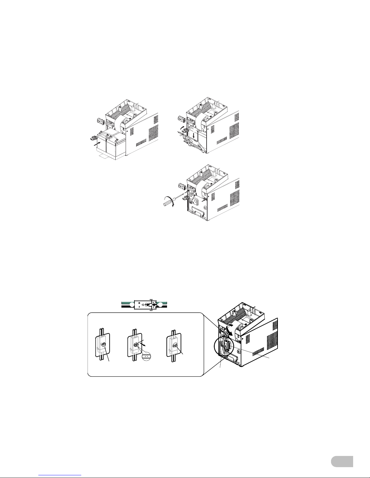
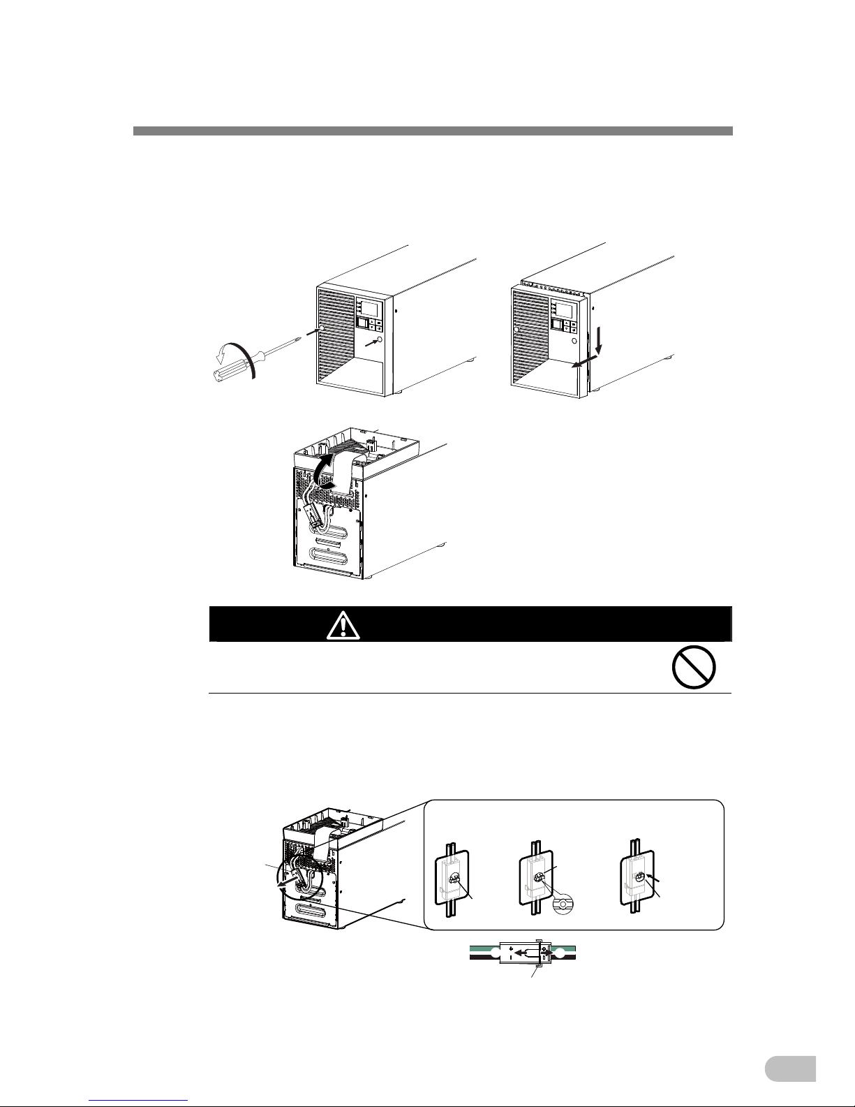
Caution (for battery replacement)
Perform replacement on a stable and flat place.
Handle the battery carefully so that you do not drop it.
Not doing so could cause injury or burns due to liquid (acid) leakage.
Use a specified battery for replacement.
Not doing so may cause a fire.
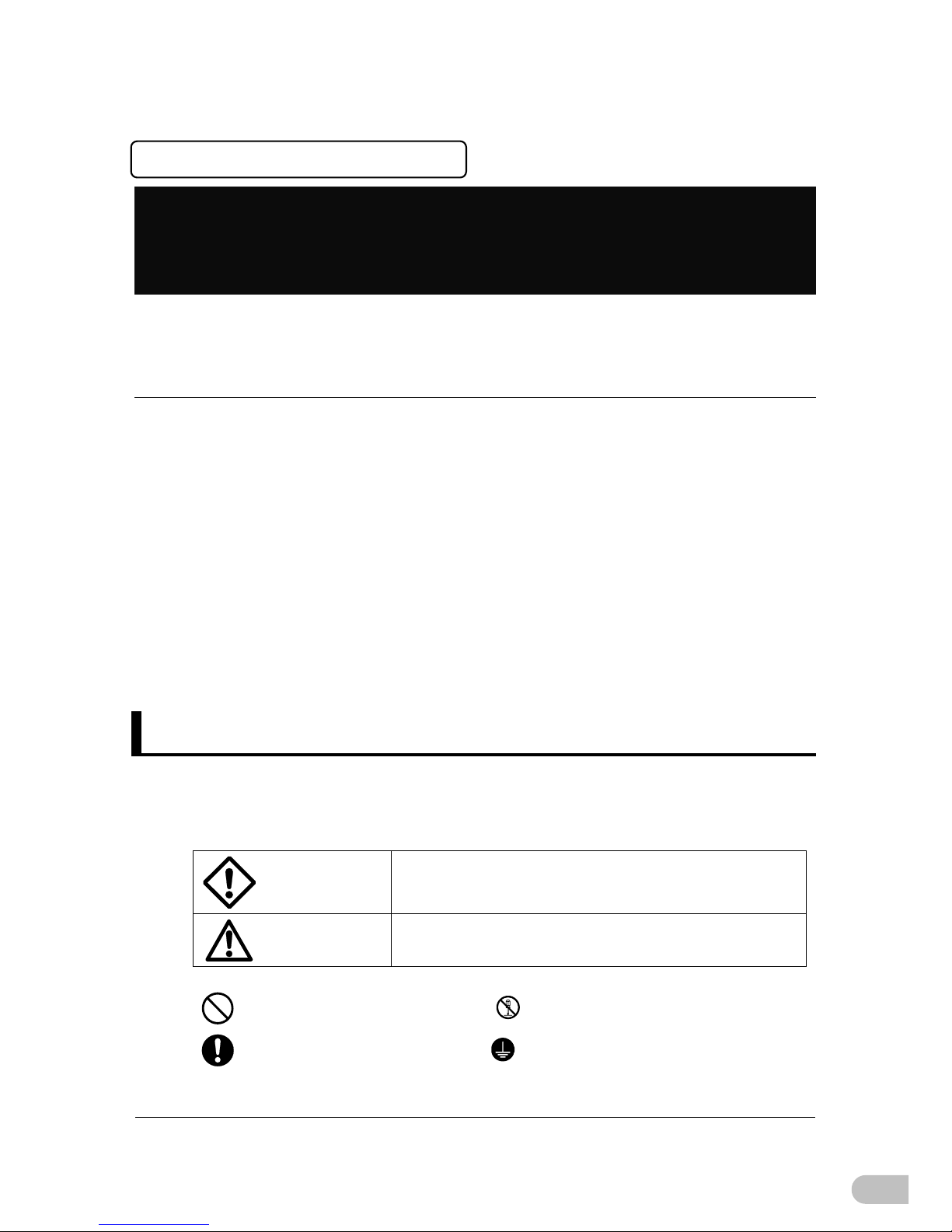
Replacement battery pack for
BNB75T (BN50T/BN75T Replacement Battery Pack)
BNB300T(BN100T/BN150T, BN220T/BN300T [required two battery packs for these
models] Replacement Battery Pack)
Do not replace the battery in a place where there is flammable gas.
Spark may occur when connecting the battery, which may cause an explosion or fire.
If fluid (dilute sulfuric acid) leaks from the battery, do not touch the fluid.
Doing so may cause blindness or burns.
If it contacts your eyes or skin, wash it out with lots of clean water and consult your
doctor.
Do not disassemble or modify the battery.
Doing so could cause dilute sulfuric acid leak, which could cause blindness and burns.
Do not drop the battery and do not expose it to strong impact.
Dilute sulfuric acid may leak.
Do not short the battery with metal objects.
Doing so could cause an electric shock, fire or burn.
Some electrical energy still remains inside the spent battery.
Do not put the battery into fire and do not break it.
The battery may explode or leak dilute sulfuric acid.
Do not use a new battery and an old battery at the same time.
Dilute sulfuric acid may leak.
A battery can present a risk of electrical shock and high short circuit current.
The following precautions should be observed when working on batteries:
a. Remove watches, rings, or other metal objects from the hands.
b. Use a screwdriver with an insulated handle.
c. Wear insulated gloves and boots.
d. Do not lay tools or metal parts on top of batteries.
e. Disconnect charging source prior to connecting or disconnecting batteries
terminals.
Note: This only applies when the UPS is used in compliance with UL standards or CE
marking.
f. Do not ground the batteries.
Battery replacement should be performed or supervised by personnel familiar with the
danger of batteries and the required precautions.