Omron XS5 User manual

CSM_XS5_DS_E_7_1
1
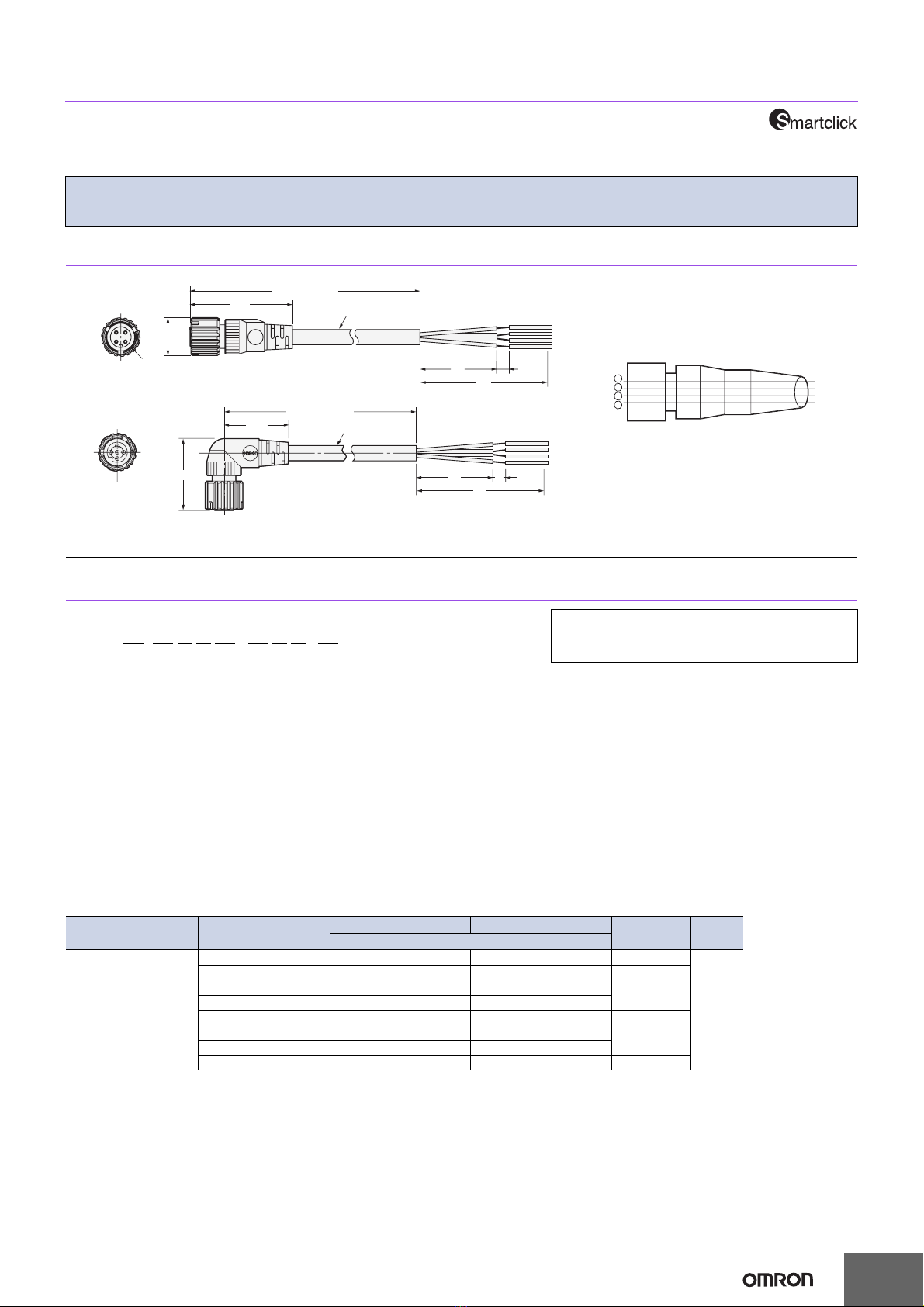
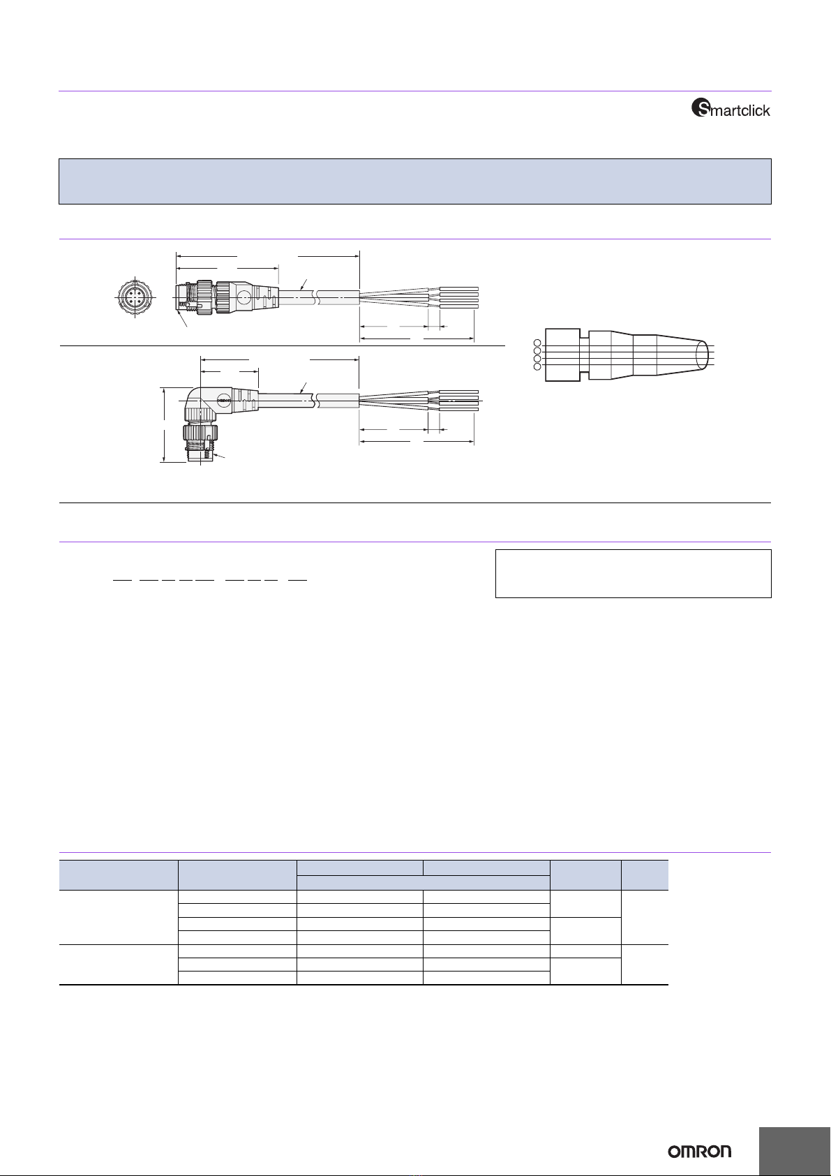
Round Water-resistant Connectors
XS5
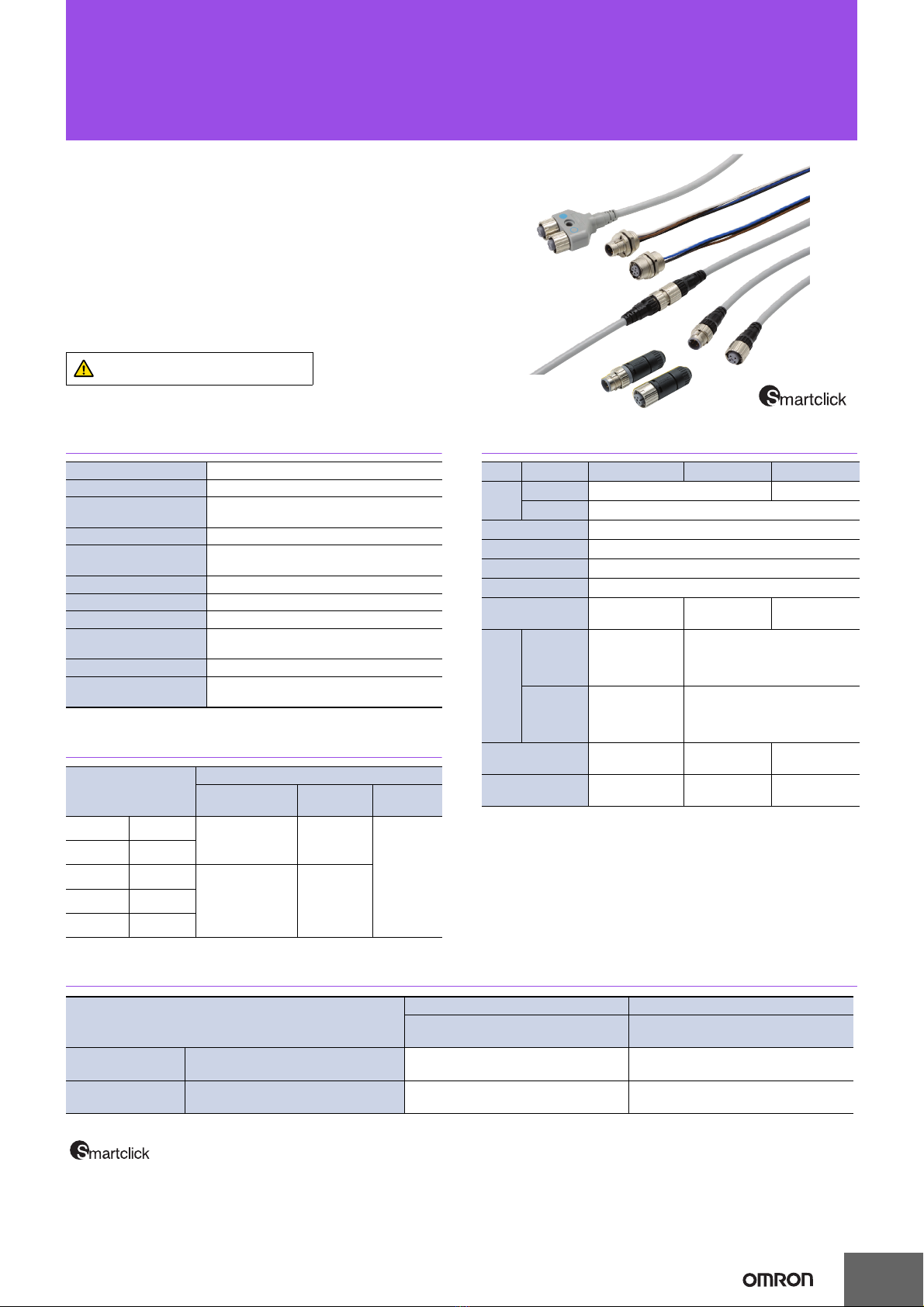
Round Water-resistive Smartclick
Connectors That Reduce Installation Work
• A newly developed lock mechanism that is compatible with round M12 connectors.
• Simply insert the Connectors, then turn them approximately 1/8 of a turn to lock.
• A positive click indicates locking.
• Features the same degree of protection (IP67) as M12 connectors.
• A full line-up of models is planned.
• Connectors with Cables are UL approved.
Refer to Safety Precautions on
page 17.
Ratings and Specifications
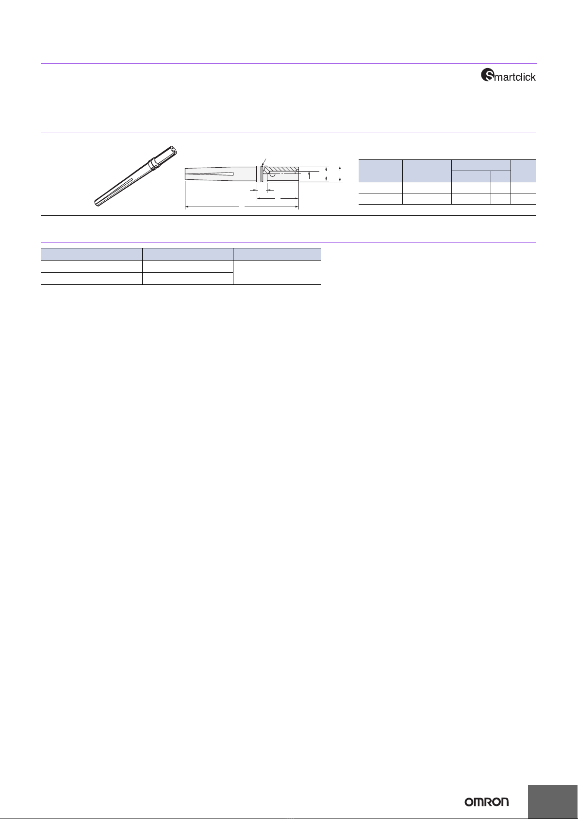
Recommended Cables for Assembly Connectors
Materials and Finish
Connection Combinations
Rated current 4 A
Rated voltage 250 VDC
Contact resistance
(connector)
40 mΩmax.
(20 mV max., 100 mA max.)
Insulation resistance 1,000 MΩ min. (at 500 VDC)
Dielectric strength
(connector)
1,500 VAC for 1 min
(leakage current: 1 mA max.)
Degree of protection IP67 (IEC60529)
Insertion tolerance 50 times min.
Lock strength Tensile: 100 N/15 s, Torsion: 1 N·m/15 s
Cable holding
strength 100 N/15 s (for cable diameter of 6 mm)
Lock operating force 0.1 N·m to 0.25 N·m
Ambient operating
temperature range −25 to 70°C
Cable outer
diameter
(mm)
Core sizes
Crimping
models
Soldering
models
Screw-on
models
for 8 dia. 7 to 8 dia. --- ---
0.18 to
0.75 mm
2
for 7 dia. 6 to 7 dia.
for 6 dia. 5 to 6 dia. Two types of
contacts are
available.
0.18 to 0.3 mm
2
0.5 to 0.75 mm
2
0.5 mm2
max.
for 4 dia. 4 to 5 dia.
for 3 dia. 3 to 4 dia.
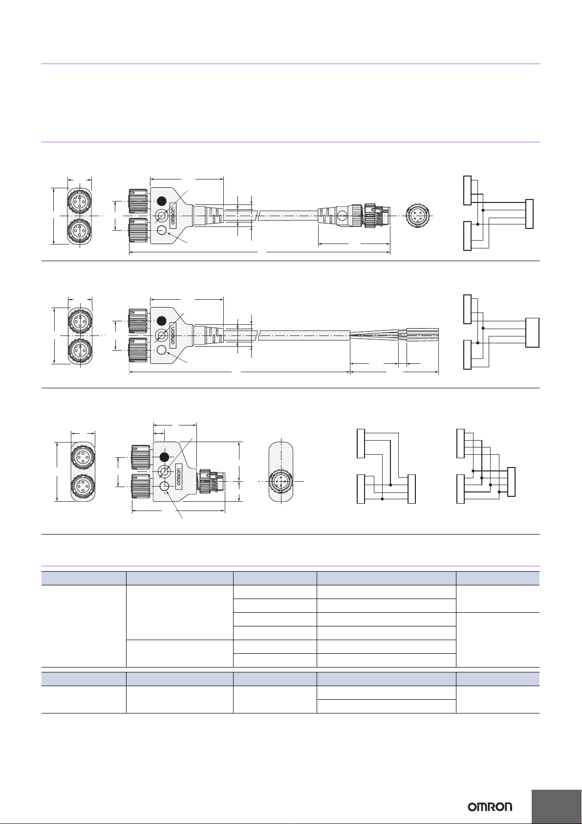
Item Model XS5F/H/W/R XS5M/P XS5C/G
Con-
tacts
Materials Phosphor bronze Brass
Finish Nickel base, 0.4-µm gold plating
Fixtures Nickel-plated zinc alloy
Fixtures (Lock) SUS
Pin block PBT resin (UL94V-0)
O-ring Rubber
Overmolding/
Cover
Polyester elas-
tomer --- PBT resin
(UL94V-0)
Cable
Vibration-
proof
robot
cable
UL CL3, 6-mm
dia., 4 cores ×
AWG20 (0.08/
110)
---
Oil-resis-
tant poly-
urethane
cable
6 dia.
4 cores ×0.5 mm2
(0.12/45)
---
Seal resin --- Epoxy resin
(UL94V-0) ---
Power supply
wires --- UL1007 AWG20 ---
is a registered trademark of the OMRON Corporation.
OMRON model No.
Smartclick Plug Connectors M12 Plug Connectors
XS5H, XS5G, XS5W (plug side),
XS5R (plug side), XS5M
XS2H, XS2G, XS2W (plug side),
XS2R (plug side), XS2M
Smartclick Socket
Connectors
XS5F, XS5C, XS5W (socket side),
XS5R (socket side), XS5P ❍
M12 Socket
Connectors
XS2F, XS2C, XS2W (socket side),
XS2R (socket side), XS2P ❍❍
: Connected by twisting.
❍: Connected by screwing.
Note: The XS@M and XS@P cannot mate with each other.

XS5
2
XS5WConnectors Connected to Cable, Socket and Plug on Cable Ends
Dimensions (Unit: mm)
Note: Oil-resistant Polyurethane Cables (XS5W-D42@-@81-P) have black covers. Vibration-proof Robot Cables (XS5W-D42@-@81-F) have warm
gray covers.
●Vibration-proof Robot Cable XS5W-D42@-@81-F
●Oil-resistant Polyurethane Cable XS5W-D42@-@81-P
40.7
L (Cable length)
44.7
6 dia. M12
Straight/straight
L (Cable length)
32.3
28.3 6 dia.
M12
Angled/angled
L (Cable length)
28.3
44.7
6 dia. M12
Angled/straight
1
2
3
4
1
2
3
4
Terminal No.
Brown
White
Blue
Black
Cable color of
core sheath
Wiring Diagram for 4 Cores
L (Cable length)
32.3
40.7
6 dia.
M12
Straight/angled

XS5
3
Model Number Legend
1. Type
W: Connector connected to cable, plug on cable
ends
2. Mating Section Form
D: DC
3. Connector Poles
4: 4 poles
4. Contact Plating
2: 0.4-µm gold plating
5. Cable Connection Direction
1: Straight/straight
2: Angled/angled
3: Straight (XS5F)/angled (XS5H)
4: Angled (XS5F)/straight (XS5H)
6. Cable Length
C: 1 m D: 2 m E: 3 m
G: 5 m J: 10m
7. Connections
8: ABrown, BWhite, CBlue, DBlack (Numbers
inside circles are terminal numbers)
8. Connectors on One End/Both Ends
1: Both ends
9. Cable Specifications
F: Vibration-proof Robot Cable
P: Oil-resistant Polyurethane Cable
Ordering Information
Use this model number legend to identify products
from their model number. When ordering, use a mod-
el number from the table in Ordering Information.
XS5W-D42@-@81-@
83 4
2 6 951 7
Cable specifications Cable
length L (m)
Straight/straight Angled/angled Minimum
order UL
Model
Vibration-proof Robot
Cable
1XS5W-D421-C81-F --- 10
Yes
2XS5W-D421-D81-F XS5W-D422-D81-F
53 XS5W-D421-E81-F ---
5XS5W-D421-G81-F XS5W-D422-G81-F
10 XS5W-D421-J81-F --- 1
Oil-resistant Polyure-
thane Cable
2XS5W-D421-D81-P --- 5---5XS5W-D421-G81-P ---
10 XS5W-D421-J81-P --- 1
Cable specifications Cable
length L (m)
Straight/angled Angled/straight Minimum
order UL
Model
Vibration-proof Robot
Cables
2XS5W-D423-D81-F XS5W-D424-D81-F 5Yes
5XS5W-D423-G81-F XS5W-D424-G81-F

XS5
4
XS5F Connector Connected to Cable, Socket on One Cable End
Dimensions (Unit: mm)
Note: Oil-resistant Polyurethane Cables (XS5F-D42@-@80-P) have black covers. Vibration-proof Robot Cables (XS5F-D42@-@80-F) have warm
gray covers.
Model Number Legend
Ordering Information
●Vibration-proof Robot Cable XS5F-D42@-@80-F
●Oil-resistant Polyurethane Cable XS5F-D42@-@80-P
Straight
6 dia.
40.7
L (Cable length)
50
30 5
M12
14.9 dia.
1
2
3
4
Brown
White
Blue
Black
Terminal No. Cable color of
core sheath
Wiring Diagram for 4 Cores
6 dia.
25.3
28.3
L (Cable length)
50
30 5
Angled
Use this model number legend to identify products
from their model number. When ordering, use a mod-
el number from the table in Ordering Information.
XS5F-D42@-@80-@
83 4
2 6 951 7
Cable specifications Cable length L (m) Straight Connectors Angled Connectors Minimum
order UL
Model
Vibration-proof
Robot Cable
1XS5F-D421-C80-F XS5F-D422-C80-F 10
Yes
2XS5F-D421-D80-F XS5F-D422-D80-F
53 XS5F-D421-E80-F XS5F-D422-E80-F
5XS5F-D421-G80-F XS5F-D422-G80-F
10 XS5F-D421-J80-F XS5F-D422-J80-F 1
Oil-resistant
Polyurethane Cable
2XS5F-D421-D80-P XS5F-D422-D80-P 5---5XS5F-D421-G80-P XS5F-D422-G80-P
10 XS5F-D421-J80-P XS5F-D422-J80-P 1
1. Type
H: Connector connected to cable,
plug on one cable end
2. Mating Section Form
D: DC
3. Connector Poles
4: 4 poles
4. Contact Plating
2: 0.4-µm gold plating
5. Cable Connection Direction
1: Straight
2: Angled
6. Cable Length
C: 1 m D: 2 m E: 3 m
G: 5 m J: 10 m
7. Connections
8: ABrown, BWhite, CBlue,
DBlack (Numbers inside circles are
terminal numbers.)
8. Connectors on One End/Both Ends
0: One end
9. Cable Specification
F: Vibration-proof Robot Cable
P: Oil-resistant Polyurethane Cable

XS5
5
XS5H Connector Connected to Cable, Plug on One Cable End
Dimensions (Unit: mm)
Note: Oil-resistant Polyurethane Cables (XS5H-D42@-@80-P) have black covers. Vibration-proof Robot Cables (XS5H-D42@-@80-F) have warm
gray covers.
Model Number Legend
Ordering Information
●Vibration-proof Robot Cable XS5H-D42@-@80-F
●Oil-resistant Polyurethane Cable XS5H-D42@-@80-P
Cable specifications Cable length L (m) Straight Connectors Angled Connectors Minimum
order UL
Model
Vibration-proof
Robot Cable
0.3 XS5H-D421-A80-F XS5H-D422-A80-F 10
Yes
1XS5H-D421-C80-F XS5H-D422-C80-F
2XS5H-D421-D80-F XS5H-D422-D80-F 5
5XS5H-D421-G80-F XS5H-D422-G80-F
Oil-resistant
Polyurethane Cable
0.3 XS5H-D421-A80-P XS5H-D422-A80-P 10
---2XS5H-D421-D80-P XS5H-D422-D80-P 5
5XS5H-D421-G80-P XS5H-D422-G80-P
44.7 6 dia.
L (Cable length)
50
30 5
M12
1
2
3
4
Brown
White
Blue
Black
Terminal No. Cable color of
core sheath
L (Cable length)
6 dia.
M12
50
30 5
32.3
25.3
Wiring Diagram for 4 Cores
Angled
Straight
Use this model number legend to identify products
from their model number. When ordering, use a mod-
el number from the table in Ordering Information.
XS5H-D42@-@80-@
83 4
2 6 951 7
1. Type
H: Connector connected to cable,
plug on one cable end
2. Mating Section Form
D: DC
3. Connector Poles
4: 4 poles
4. Contact Plating
2: 0.4-µm gold plating
5. Cable Connection Direction
1: Straight
2: Angled
6. Cable Length
A: 0.3 m C: 1 m D: 2 m
G: 5 m
7. Connections
8: ABrown, BWhite, CBlue,
DBlack (Numbers inside circles
are terminal numbers)
8.
Connectors on One End/Both Ends
0: One end
9. Cable Specifications
F: Vibration-proof Robot Cable
P: Oil-resistant Polyurethane
Cable

XS5
6
XS5G Assembly Connector Plugs
Dimensions (Unit: mm)
Ordering Information
Note: XS5G Screw-on Plugs cannot be connected to side by side to the CN1 and CN2 connectors of XS2R or XS5R Y-Joint Sockets/Plugs.
No. of
poles
Connection
method
Suitable cable dia.
(mm)
Straight Connectors Angled Connectors Minimum order
Model
4
Crimping
6 mm (5 to 6) XS5G-D4C1 ---
50
4 mm (4 to 5) XS5G-D4C3 ---
3 mm (3 to 4) XS5G-D4C5 ---
Soldering
6 mm (5 to 6) XS5G-D421 XS5G-D422
4 mm (4 to 5) XS5G-D423 XS5G-D424
3 mm (3 to 4) XS5G-D425 XS5G-D426
Screw-on
6 mm (5 to 6) XS5G-D4S1 XS5G-D4S2
4 mm (4 to 5) XS5G-D4S3 XS5G-D4S4
3 mm (3 to 4) XS5G-D4S5 XS5G-D4S6
8 mm (7 to 8) XS5G-D4S7 ---
7 mm (6 to 7) XS5G-D4S9 ---
5 Screw-on
6 mm (5 to 6) XS5G-D5S1 ---
4 mm (4 to 5) XS5G-D5S3 ---
3 mm (3 to 4) XS5G-D5S5 ---
8 mm (7 to 8) XS5G-D5S7 ---
7 mm (6 to 7) XS5G-D5S9 ---
14.9 dia.
49.3
14.2 dia.
M12
XS5G-D4C@(Crimping Model)
XS5G-D42@(Soldering Model)
Straight Connectors
37.7
14.9 dia.
23
M12
XS5G-D42@(Soldering Model)
Angled Connectors
58.7
16 dia.20 dia.
14.9 dia.
XS5G-D@S@(Screw-on Connectors, Applicable Cable Outer Diameter: 7 or 8 mm)
Straight Connectors
58.7
14 dia.20 dia. 14.9 dia.
XS5G-D@S@(Screw-on Connectors, Applicable Cable Outer Diameter: 3, 4, or 6 mm)
Straight Connectors
39.7
39.6
20 dia.
14 dia.
XS5G-D@S@(Screw-on Connectors)
Angled Connectors

XS5
7
XS5U (Crimping Pin for XS5G)
Dimensions (Unit: mm)
Ordering Information
Note: Orders are accepted in multiples of the minimum order.
Suitable core size (mm2)Model Minimum order
0.18 to 0.3 XS5U-3121 100
0.5 to 0.75 XS5U-3122
XS5U-312@
Plug Pin
2.3 dia.2 dia.
C dia.
1.5
1 dia.
B
Slit
A
* A special tool must be used for crimping. For details, refer to page 13.
Dimensions
Model Suitable core
size (mm2)
Dimension (mm) No. of
slits
ABC
XS5U-3121 0.18 to 0.3 22.6 6.1 0.8 1
XS5U-3122 0.5 to 0.75 22.7 6.2 1.3 0

XS5
8
XS5C Assembly Connector Sockets
Dimensions (Unit: mm)
Ordering Information
No. of
poles
Connection
method
Suitable cable dia.
(mm)
Straight Connectors Angled Connectors Minimum order
Model
4
Crimping
6 mm (5 to 6) XS5C-D4C1 XS5C-D4C2
50
4 mm (4 to 5) XS5C-D4C3 XS5C-D4C4
3 mm (3 to 4) XS5C-D4C5 XS5C-D4C6
Soldering
6 mm (5 to 6) XS5C-D421 XS5C-D422
4 mm (4 to 5) XS5C-D423 XS5C-D424
3 mm (3 to 4) XS5C-D425 XS5C-D426
Screw-on
6 mm (5 to 6) XS5C-D4S1 XS5C-D4S2
4 mm (4 to 5) XS5C-D4S3 XS5C-D4S4
3 mm (3 to 4) XS5C-D4S5 XS5C-D4S6
8 mm (7 to 8) XS5C-D4S7 ---
7 mm (6 to 7) XS5C-D4S9 ---
5 Screw-on
6 mm (5 to 6) XS5C-D5S1 ---
4 mm (4 to 5) XS5C-D5S3 ---
3 mm (3 to 4) XS5C-D5S5 ---
8 mm (7 to 8) XS5C-D5S7 ---
7 mm (6 to 7) XS5C-D5S9 ---
XS5C-D4C@(Crimping Model)
XS5C-D42@(Soldering Model)
Straight Connectors
M12
43.4
14.9 dia. 14.2 dia.
M12
31.8
14.9 dia.
23
XS5C-D4C@(Crimping Model)
XS5C-D42@(Soldering Model)
Angled Connectors
54.9
20 dia. 14.9 dia. 16 dia.
XS5C-D@S@(Screw-on Connectors, Applicable Cable Outer Diameter: 7 or 8 mm)
Straight Connectors
54.9
20 dia. 14.9 dia. 14 dia.
XS5C-D@S@(Screw-on Connectors, Applicable Cable Outer Diameter: 3, 4, or 6 mm)
Straight Connectors
14.9 dia.
35.9
39.6
14 dia.
20 dia.
XS5C-D@S@(Screw-on Connectors)
Angled Connectors

XS5
9
XS5U (Crimping Pin for XS5C)
Dimensions (Unit: mm)
Ordering Information
Orders are accepted in multiples of the minimum order.
Suitable core size (mm2)Model Minimum order
0.18 to 0.3 XS5U-2221 100
0.5 to 0.75 XS5U-2222
XS5U-222@
Socket Pin Slit
2.3 dia.2 dia.
C dia.
1.5
B
A
* A special tool must be used for crimping. For details, refer to page 13.
Dimensions
Model Suitable core
size (mm2)
Dimension (mm) No. of
slits
A B C
XS5U-2221 0.18 to 0.3 16.7 6.1 0.8 1
XS5U-2222 0.5 to 0.75 16.8 6.2 1.3 0

XS5
10
XS5R Y-Joint Plug/Socket Connectors
Dimensions (Unit: mm)
Ordering Information
Note 1. Ask your OMRON representative about other specifications.
2. XS2G/XS5G Assembled Connectors with screw connections cannot be connected to both CN1 and CN2 at the same time.
Cable Connector Cable length (m) Model Minimum order
With cable
Connectors on both cable
ends
0.5 XS5R-D426-B11-F 10
1XS5R-D426-C11-F
2XS5R-D426-D11-F
5
3XS5R-D426-E11-F
Connector on one cable
end
2XS5R-D426-D10-F
5XS5R-D426-G10-F
Cable Connector Cable length (m) Model Minimum order
With no cable Y-Joint Plug/Socket — XS5R-D426-1 10
XS5R-D426-5
XS5R-D426-@11-F
Connectors on Both Ends (Y-Joint Plug/Socket)
1
2
3
44
3
2
1
1
2
3
4
CN2
CN1
1
43
2
1
43
2
1
43
2
1
43
2
1
43
2
1
43
2
1
43
2
1
43
2
45.5
4.6 dia.
18.0
35.0
CN1
CN2
15.0
Blue marking 8.5
13.6
L
44.7
Wiring Diagram
XS5R-D426-@10-F
Connectors on One Cable End (Y-Joint Socket)
1
43
2
1
43
2
1
43
2
1
43
2
18.0
15.0
35.0
CN1
CN2
Blue marking
45.5
4.6 dia.
30±5
50+20
−10
5±3
8.5 13.6
L
1
2
3
4
1
2
3
4
Black
Blue
White
Brown
CN2
CN1
Wiring Diagram
4
3
2
1
4
3
2
1
4
3
2
1
4
3
2
1
4
3
2
1
4
3
2
1
CN2
CN1
CN0
CN2
CN1 CN0
1
43
2
1
43
2
58.3
27
4.5 dia.
CN2
(37) 18
15
CN1
CN0
Blue marking
7
24.5
12.5
Wiring Diagram
XS5R-D426-1 XS5R-D426-5
XS5R-D426-@
Y-Joint Plug/Socket without Cable

XS5
11
XS5P Panel-mounting Sockets
Dimensions (Unit: mm)
Panel Cutout
Note 1. The panel cutout dimension is the same for Front-locking and Rear-
locking Sockets.
2. Rotational positioning is not possible for connector rotation.
Wiring and Wire Specifications
Wiring
Wire Specifications
Ordering Information
2
3
4
120
White
Brown
Black
Blue
18
(20)
500
22.1
11.9
2.5
14.6 dia.
PG9
2.8
M12
17
18
10±3
XS5P-D426-5
Panel-mounting Sockets with Rear Locks
2
3
4
1
M12 PG9
(20)
500
22.1
18
20
White
Blue
Brown
Black
17
18
10.5 2.5
10±3
13.9 dia.
2.8
XS5P-D427-5
Panel-mounting Sockets with Front Locks
Panel Cutout Dimension
Panel thickness = 1 to 4 mm
15.3
+0.1
0
dia.
Pin number Color
1Brown
2White
3Blue
4Black
Item Specification
Specification UL1007
Nominal size AWG20
Configuration
Number of wires 21
Wire diameter 0.18
Standard outer diameter 1.8
Type Lock Cable length (m) Model Minimum order
With cable Rear lock 0.5 XS5P-D426-5 10
Front lock XS5P-D427-5

XS5
12
XS5M Panel-mounting Plugs
Dimensions (Unit: mm)
Panel Cutout
Note 1. The panel cutout dimension is the same for Front-locking and Rear-
locking Sockets.
2. Rotational positioning is not possible for connector rotation.
Wiring and Wire Specifications
Wiring
Wire Specifications
Ordering Information
2.8
M12 PG9
500
22.8
18
17
White
Brown
Blue
Black
18
20
10
2.8
10±3(20)
2
3
4
1
XS5M-D426-5
Panel-mounting Plugs with Rear Locks
1
4
3
2
PG9
M12
(20)
500
22.8
18
20
White
Brown
Blue
Black
18
17
82.8
10±3
2.8
XS5M-D427-5
Panel-mounting Plugs with Front Locks
15.3+0.1
0 dia.
Panel Cutout Dimension
Panel thickness = 1 to 4 mm
Pin number Color
1Brown
2White
3Blue
4Black
Item Specification
Specification UL1007
Nominal size AWG20
Configuration
Number of wires 21
Wire diameter 0.18
Standard outer diameter 1.8
Type Lock Cable length (m) Model Minimum order
With cable Rear lock 0.5 XS5M-D426-5 10
Front lock XS5M-D427-5

XS5
13
Tools
Use the Crimp Tool to crimp a cable core to the XS5U or XS2U
Crimping Pin used with the XS@C or XS@G Crimping Connector.
•The XY2F-0002 Crimp Tool is DMC's AFM8 (M22520/2-01).
•Mount the XY2F-0003 Locator (sold separately) to the locator
guide of the Crimp Tool with a screw provided with the XY2F-0003
Locator.
Extraction Procedure
(1) Disconnecting Components
•Disconnect all components on the cap side from the cover.
(2) Extracting Pin Block
•Insert the claws of the Tool into the four holes of the cover.
•Make sure that the pin block is outside the Tool.
•Press the Tool so that the guides of the Tool are in close contact.
Then pull the pin block straight.
Precaution for Safe Use
•The pin block must not be extracted from the same Connector
more than 3 times, otherwise the proper degree of protection of the
pin block or Connector will not be maintained.
Crimp Tool
XY2F-0002
Locator
XY2F-0003
5
4
3
2
1
8
7
6
R
A
I
S
E
T
O
R
O
T
A
T
E
SEL.
NO.
P
U
S
H
P
O
S
I
T
I
O
N
E
R
A
N
D
R
O
T
A
T
E
9
0
°
T
O
I
N
S
T
A
L
L
R
O
T
A
T
E
9
0
°
T
O
I
N
S
T
A
L
L
Tool in open position
Tool in closed
position
XY2F-0002
Crimp Tool
XY2F-0003
Locator
Selector dial
(Set to 6.)
Locator guide
Model
XY2F-0002
XY2F-0003
Pin-block Extraction Tool
XY2F-0001
Use this tool to extract a Pin Block from the covers in order to make
wiring changes or corrections after the cover has been mounted to the
pin block for Connector Assemblies (XS@C/XS@G, soldering/
crimping). Model
XY2F-0001
Pin block Cover Rubber
bushing
Cable
clamp
Cap
Holes
Claws
Tool
Pin block
Guide
Cover Cover
Pin block
Guide
Extracting
direction

XS5
14
Assembly Procedure for XS5C/XS5G Connector Assemblies
(1) Connector and Cable External Diameters
•Connectors for 6-, 4-, and 3-mm-diameter Cables (i.e., Cables that
are 5 to 6, 4 to 5, and 3 to 4 mm in diameter respectively) are
available. When assembling a Connector used with a cable, make
sure that the external diameter of the Connector is suited to that of
the cable.
•Connectors for 6-mm-diameter Cables use white cable clamps.
Connectors for 4- and 3-mm-diameter Cables use black cable
clamps.
A watertight bushing for 6-mm-diameter Cable has no stripe, that
for 4-mm-diameter Cable has a single stripe, and that for 3-mm-
diameter Cable has two stripes.
Note: When connecting a commercially available cable to a
connector assembly, use a cable with an outside diameter of 3
to 6 mm and core sizes of 0.18 to 0.75 mm2for crimping
connectors and 0.5 mm2maximum for soldering connectors.
(2) Component Insertion
•As shown in the above illustration, connect the above components
to the Cable with its end processed.
(3) Wiring (Processing Cable Ends)
•Strip 10 mm of the Cable sheath and 4 mm of each core.
•Before soldering cores and solder cup pins together, solder-coat
each of them.
•The following conditions are recommended for soldering each
solder cup pin.
Soldering iron: 30 to 60 W
Soldering temperature: 280°C to 340°C
Soldering period: 3 s max.
•The length marked *A should be 6.5 mm max., otherwise the
proper degree of protection of the connector will not be maintained.
•Strip 14 mm of the Cable sheath and 4 mm of each core.
•Make sure that each core is not damaged and its end strands are
not spread out.
•Mount the XY2F-0003 Locator to XY2F-0002 Crimping Tool, both
of which are sold separately, and set the selector dial of the
Crimping Tool to 6 for the XS5U-@@21 and to 7 for the XS5U-
@@22.
•After mounting the crimping pins to the Locator, fully insert the
cores to the crimping pins.
•Squeeze the handle of the Crimp Tool to press-fit the cores to the
crimping pins.
(Squeeze the handle firmly until the handle automatically returns to
the release position.)
•After press-fitting the cores to the pins, insert the pins into the pin
clamp as shown in the illustration. Then make sure that the lead
colors correspond to the pin clamp numbers that are identical to
the connector pin numbers.
Crimping/Soldering Connectors
Screw-on Connectors
Cover
Watertight
bushing Cable
clamp Cap
Cover
Ring (Angled models only) *
Watertight
bushing
Cable clamp Cap
Straight Connectors
Angled Connectors
* A ring is not required for Screw-on Connectors.
Cover
Cover
Watertight bushing
Watertight
bushing
Cable clamp
Cable clamp
Cap
Cap
Ring *1
(
*2
)
Confirm that you have all of the required parts.
Insulation caps and insulation tubes are included with
5-pole Connectors (XS2C-D5S@and XS2G-D5S@).
*1. Rings are not required with 7-mm and 8-mm cables.
*2. Insert the waterproof bushing for 7-mm and 8-mm
cables in the direction shown in the diagram.
Soldering Connectors
Crimping Connectors
46
6±0.5 *A
410
0
−4
Crimping
Pin clamp Press
1 to 1.5
Wiring

XS5
15
•Tentatively insert the pins to the pin block holes so that the key on
the pin block will coincide with the key groove on the pin clamp.
Then insert the cable along with the pin clamp.
•Loosen the screws on pins 1 to 4 and insert the cores according to
the pin numbers.
•Use the dedicated Screwdriver (XW4Z-00B)*and tighten the
screws securely so that the cores do not pull out (tightening torque:
0.15 to 0.2 N·m).
•Five-pole Connectors
•Strip the cable sheath for a total of 15 mm and strip the core
covering for 8 mm for the core to connect to pin 5.
•Connect the core to pin 5 (in the center) first.
•Insert the core from the side of the hold with the tab and tighten the
screw securely (tightening torque: 0.15 to 0.2 N·m), and then cut
off the excess wire with wire cutters.
•Bend the cable as shown below, attached the enclosed insulation
cap, and then strip the other cores.
•Connect the cores to pins 1 to 4.
Connecting Shielded Cables to Five-pole Connectors
•Place the insulation tub on the drain line of the shield and connect
it to the terminal.
•Tighten the screw and then check visually to see if there is
insulation between the cores.
•Connect the cores to pins 1 to 4.
* When tightening the screws, use the dedicated XW4Z-00B
Screwdriver that matches with the screw-slot dimensions.
(4) Inserting Pin Block
•Mount the cover to the pin block so that the triangle mark on the pin
block will coincide with the triangle mark on the cover.
•If the cover is used for an Angled model, the relationship between
the position of the polarity key on the engaged side and cable
connection direction will be determined by the direction in which
the positioning key is inserted into the cover, which can be rotated
by 90°.
•Fully insert the positioning key until the positioning key is hidden by
the casing.
Screw-on Connectors
Pin Block Pin Clamp
Key groove Key groove
Key XS5C use XS5G use
6±0.5
Insertion
8
12
12±0.5
Cable End Processing
•Four-pole Connectors
87
8
12
Conductors for
pins 1 to 4
Conductors for
pin 5
Screw
Dedicated
screwdriver
Dedicated
screwdriver
Screw
Ta b
Insulation cap
Insulation tube
Drain line
XW4Z-00B
Screwdriver
Lock spring O-ring
Triangle mark
Positioning key
(triangle mark)
Polarity key
Pin Block
(Soldering Model)
Cover
(Straight Model)
(Crimping Model) (Angled Model)

XS5
16
•Align the triangular marks on the pin block and cover and insert the
pin block into the cover.
•Press them together firmly (0.39 to 0.49 N·m) until the pin block
does not come out of the cover.
(5) Mounting Cap
•After mounting the cover to the pin block and the cover snaps into
place, tighten the cap securely by hand within a torque of 0.39 and
0.49 N·m.
Note: If the cap is not tighten securely enough, the degree of
protection (IP67) may not be maintained or vibration may
cause the cap to become loose. Do not tighten the cap with
pliers or similar tools; they may damage the cap.
•After fully tightening the cap, length A should be approximately one
of the following according to the cable external diameter and the
Connector model.
(6) After Assembly
•Confirm the insulation between cores after completing assembly.
Recommended Cables
When connecting a commercially available cable to a connector
assembly, use a cable with an outside diameter of 3 to 6 mm and core
sizes of 0.18 to 0.75 mm2for crimping connectors and 0.5 mm2
maximum for soldering connectors.
Connector Arrangement
For safety, when constructing a connection system between a Sensor
and panel with a connector, make sure that the connector plug is on
the Sensor side and the connector socket is on the panel side (i.e.,
the female pins are located on the power-supply side).
Connecting the XS5
1. Connecting the XS5 Plug and Socket
•Align the projection on the plug cover with the polarity key on the
socket, then insert the plug all the way in.
•Hold the knurled socket grip, then insert the projection on the plug
into the groove of the socket.
•Turn the knurled grips of the socket clockwise approximately 45
degrees in respect to the plug. A click will indicate that the
Connectors are locked. The locking condition can also be
confirmed by the alignment marks on the plug and socket.
2. Connecting the XS5 and XS2
•Align the projection on the plug cover with the polarity key on the
socket, then insert the plug all the way in.
•In the same way as when connecting two XS2 Connectors, screw
the knurled grip in the clockwise direction.
•Use your fingers to tighten the Connectors sufficiently.
Connector Cable external diameter (mm)
6 mm 5 mm 4 mm 3 mm
For 6-mm-dia. cable 1 0 --- ---
For 4-mm-dia. cable --- 2 1 ---
For 3-mm-dia. cable --- --- 2 1
Triangle mark
Pin block
Cover lock
Pin Block
(Screw-mounting Connectors) Cover
Cap
A
Sensor Side Connecting Cable Panel Side
(Power-supply Side)
(Plug) (Socket) (Plug) (Socket)
Protrusion on
cover aligns with
polarity key.
Polarity key
Alignment marks

XS5
17
Safety Precautions
Do not use the Connectors in an atmosphere or environment that
exceeds the specifications.
Connector Connection and Disconnection
•When connecting or disconnecting Connectors, be sure to hold the
Connectors by hand.
•Do not hold the cable when disconnecting Connectors.
•When mating Connectors, be sure to insert the plug all the way to
the back of the socket before attempting to lock the Connectors.
•Do not use tools of any sort to mate the Connectors. Always use
your hands. Pliers or other tools may damage the Connectors.
•When mating the Connectors to XS2 or other M12 Connectors,
tighten the lock by hand to a torque of 0.39 to 0.49 N⋅m.
Wiring
•Always confirm wiring diagrams before wiring sensors, limit
switches, or other devices.
•Lay the cables so that external force is not applied to the
Connectors. Otherwise, the degree of protection (IP67) may not be
achieved.
Degree of Protection
•The degree of protection of Connectors (IP67) is not for a fully
watertight structure. Do not the Connectors underwater.
•Do not step on or place any objects on the Connectors. Doing so
may damage the Connectors.
General Precautions
•Do not pull excessively on the Connectors or cables. Do not install
the Connectors or cables in any way that would place a load
directly on the mating section or cable connections. Doing so can
damage the Connectors or break the wires inside the cables.
•Install the Connectors and cables where they will not be stepped
on to prevent the wires inside the cables from being broken and to
prevent the Connectors from being damaged. If the Connectors or
cables must be installed where they might be stepped on, protect
them with covers.
•Refer to the specifications for your cables before bending the
cables and do not bend them past their minimum bending radius.
•If sensors or switches are not attached during installation, protect
the mating surface of the Connector with a XS2Z-22 Waterproof
Cover of XS2Z-14/15 Dust Cover.
Precautions for Correct Use

Read and Understand This Catalog
Please read and understand this catalog before purchasing the products. Please consult your OMRON representative if you have any questions or
comments.
Warranty and Limitations of Liability
WARRANTY
OMRON's exclusive warranty is that the products are free from defects in materials and workmanship for a period of one year (or other period if specified)
from date of sale by OMRON.
OMRON MAKES NO WARRANTY OR REPRESENTATION, EXPRESS OR IMPLIED, REGARDING NON-INFRINGEMENT, MERCHANTABILITY, OR
FITNESS FOR PARTICULAR PURPOSE OF THE PRODUCTS. ANY BUYER OR USERACKNOWLEDGES THAT THE BUYER OR USERALONE HAS
DETERMINED THAT THE PRODUCTS WILL SUITABLY MEET THE REQUIREMENTS OF THEIR INTENDED USE. OMRON DISCLAIMSALLOTHER
WARRANTIES, EXPRESS OR IMPLIED.
LIMITATIONS OF LIABILITY
OMRON SHALL NOT BE RESPONSIBLE FOR SPECIAL, INDIRECT, OR CONSEQUENTIAL DAMAGES, LOSS OF PROFITS OR COMMERCIAL LOSS
IN ANY WAY CONNECTED WITH THE PRODUCTS, WHETHER SUCH CLAIM IS BASED ON CONTRACT, WARRANTY, NEGLIGENCE, OR STRICT
LIABILITY.
In no event shall the responsibility of OMRON for any act exceed the individual price of the product on which liability is asserted.
IN NO EVENT SHALL OMRON BE RESPONSIBLE FOR WARRANTY, REPAIR, OR OTHER CLAIMS REGARDING THE PRODUCTS UNLESS
OMRON'S ANALYSIS CONFIRMS THAT THE PRODUCTS WERE PROPERLY HANDLED, STORED, INSTALLED,AND MAINTAINEDAND NOT
SUBJECTTO CONTAMINATION,ABUSE, MISUSE, OR INAPPROPRIATE MODIFICATION OR REPAIR.
Application Considerations
SUITABILITY FORUSE
OMRON shall not be responsible for conformity with any standards, codes, or regulations that apply to the combination of products in the customer's
application or use of the products.
At the customer's request, OMRON will provide applicable third party certification documents identifying ratings and limitations of use that apply to the
products. This information by itself is not sufficient for a complete determination of the suitability of the products in combination with the end product,
machine, system, or other application or use.
The following are some examples of applications for which particular attention must be given. This is not intended to be an exhaustive list of all possible
uses of the products, nor is it intended to imply that the uses listed may be suitable for the products:
Outdoor use, uses involving potential chemical contamination or electrical interference, or conditions or uses not described in this catalog.
Nuclear energy control systems, combustion systems, railroad systems, aviation systems, medical equipment, amusement machines, vehicles,
safety equipment, and installations subject to separate industry or government regulations.
Systems, machines, and equipment that could present a risk to life or property.
Please know and observe all prohibitions of use applicable to the products.
NEVER USE THE PRODUCTS FORAN APPLICATION INVOLVING SERIOUS RISK TO LIFE OR PROPERTY WITHOUT ENSURING THAT THE
SYSTEMASAWHOLE HAS BEEN DESIGNED TO ADDRESS THE RISKS,AND THAT THE OMRON PRODUCTS ARE PROPERLY RATEDAND
INSTALLED FOR THE INTENDED USE WITHIN THE OVERALLEQUIPMENT OR SYSTEM.
PROGRAMMABLE PRODUCTS
OMRON shall not be responsible for the user's programming of a programmable product, or any consequence thereof.
Disclaimers
CHANGE IN SPECIFICATIONS
Product specifications and accessories may be changed at any time based on improvements and other reasons.
It is our practice to change model numbers when published ratings or features are changed, or when significant construction changes are made.
However, some specifications of the products may be changed without any notice. When in doubt, special model numbers may be assigned to fix or
establish key specifications for your application on your request. Please consult with your OMRON representative at any time to confirm actual
specifications of purchased products.
DIMENSIONSAND WEIGHTS
Dimensions and weights are nominal and are not to be used for manufacturing purposes, even when tolerances are shown.
PERFORMANCE DATA
Performance data given in this catalog is provided as a guide for the user in determining suitability and does not constitute a warranty. It may represent the
result of OMRON’s test conditions, and the users must correlate it to actual application requirements. Actual performance is subject to the OMRON
Warranty and Limitations of Liability.
ERRORS AND OMISSIONS
The information in this document has been carefully checked and is believed to be accurate; however, no responsibility is assumed for clerical,
typographical, or proofreading errors, or omissions.
2012.4
In the interest of product improvement, specifications are subject to change without notice.
OMRON Corporation
Industrial Automation Company
http://www.ia.omron.com/
(c)Copyright OMRON Corporation 2012 All Right Reserved.
This manual suits for next models
126
Table of contents
Other Omron Cables And Connectors manuals

Omron
Omron XS5 T Series User manual

Omron
Omron ZFV-XC Series B(R)V2 User manual

Omron
Omron FZ-VSJ User manual

Omron
Omron SENSOR ACCESSORIES User manual

Omron
Omron XS5H User manual

Omron
Omron M12 - User manual

Omron
Omron F3SN-A - User manual

Omron
Omron XS5F User manual

Omron
Omron CS1W-CIF31 User manual

Omron
Omron CS1W User manual
Popular Cables And Connectors manuals by other brands

Siemens
Siemens SENTRON VL160X operating instructions

Festo
Festo NEBM-S1G9-E N-S1G9 Series Assembly instructions

Kohler
Kohler K-97172 Installation and care guide

ELEY
ELEY 1045 Assembly/installation instructions

Marmitek
Marmitek SPLIT 414 Brochure & specs

HUBER+SUHNER
HUBER+SUHNER MASTERLINE Ultimate Small Cell installation manual