Omron SENSOR ACCESSORIES User manual

A-1
Accessories for Standard Sensors (photoelectric, inductive, capacitive)
Sensor Accessories
Cable connectors . . . . . . . . . . . . . . A-2
Extended wiring accessories . . . . . . A-19
Mounting brackets . . . . . . . . . . . . A-28
Reflectors . . . . . . . . . . . . . . . . . A-34

A-2 Standard Photoelectric Sensors
Cable Connectors
Product group Cable Connectors
Type General purpose (screw) General purpose
(snap)
General purpose -
extended wiring
small size
(screw or snap)
Order reference Y92E-M08 Y92E-M12 Y92E-MS08 XS2F-@-A XS3F-@-A
Applicable/
Recommended Sensors
Inductive:
E2A-@-M5,
E2A-@-M3,
E2E small diameter,
E2EL, E2C-EDA
photoelectric: E3Z,
E3G-L1/L3, E3C,
E3X
All sensors with
M8-junction connec-
tors -M3J, -M5J
Photoelectric:
E3F2, E3G-(M)R,
E3G-(M)L7, E3S-C,
E3MV, E3NT
Inductive:
E2@-@-M1, E2E,
E2E@, E2F
All sensors with
M12 junction connec-
tor -M1J
Inductive:
E2A-@-M5,
E2A-@-M3,
E2E small diameter,
E2EL, E2C-EDA
Photoelectric: E3Z,
E3G-L1/L3, E3C,
E3X
See Y92E-M12 plus
AC 2-wire types:
E2E-@Y, E2F-@Y,
E3F2-@Z
Inductive:
E2A-@-M3,
E2E small diameter,
E2EL, E2C-EDA
Photoelectric:
E3Z, E3G-L1/L3,
E3C, E3X
All sensors with
M8-junction connec-
tors -M3J
Features - 3 or 4 pin
- LED optionally
- 3, 4 or 5 wire
- LED optionally 3 or 4 pin 2, 3, 4 or 5 wire 4 pin
Size M8 M12 M8 M12 M8
Material Nut Brass (CuZn) or
zinc diecast (ZnAl Cu) PUR brass
Cable PVC or PUR PVC or PUR PVC
Product group Cable Connectors
Type Robot cable (vibration resistant) Detergent resistant Fire retardant Spatter proof
Order reference XS3F-@-R XS2F-@-R Y92E-S08 Y92E-S12 XS2F-@-F XS2F-@-AS
Applicable/
Recommended Sensors See Y92E-M08 See Y92E-M12 E3ZM E2FM See Y92E-M12 E2FM
Features 4 pin 3, 4 or 5 wire 3 or 4 pin 4 wire 3, 4 or 5 wire 4 wire
Size M8 M12 M8 M12 M12 M12
Material Nut brass stainless steel brass brass
Cable PVC PVC PVC Polyethylene

A-3
General Purpose Cable Connectors (M8 / M12)
Y92E
Model Number Legend
1. Connector type
M: standard female screw on connector
S: stainless steel female screw on connector
MM: male metric screw plug
MS: female snap connector
2. Size
08: M8 size
12: M12 size
3. Material
PVC: PVC cable
PUR: PUR cable
4. Nr of poles
3: 3 poles
4: 4 poles
5: 5 poles
5. Shape
A: angled
S: straight
6. Length
2M: standard 2 m length
5M: standard 5 m length
10M: standard 10 m length
7. LED
LED: with LED
[blank]: no LED
8. Specials
9. Supply code
-L designed and manufactured by Lumberg
-H designed and manufactured by Hirschmann
Ordering information
General purpose models
1234
Y92E - @@@@ - @@@ - @
56789
Product description 1Connector Size Cable
material Poles Type Length
(m) LED Nut
Y92E-M08PUR3A2M-x
female M8
PUR
3
Angled
2
no -H: Zinc diecast (ZnAl Cu)
-L: brass (CuZn)
Y92E-M08PUR3A5M-x 5
Y92E-M08PUR3A10M-x 10
Y92E-M08PUR3S2M-x
Straight
2
Y92E-M08PUR3S5M-x 5
Y92E-M08PUR3S10M-x 10
Y92E-M08PUR4A2M-x
4
Angled
2
Y92E-M08PUR4A5M-x 5
Y92E-M08PUR4A10M-x 10
Y92E-M08PUR4S2M-x
Straight
2
Y92E-M08PUR4S5M-x 5
Y92E-M08PUR4S10M-x 10
Y92E-M08PVC3A2M-x
PVC
3
Angled
2
Y92E-M08PVC3A5M-x 5
Y92E-M08PVC3A10M-x 10
Y92E-M08PVC3S2M-x
Straight
2
Y92E-M08PVC3S5M-x 5
Y92E-M08PVC3S10M-x 10
Y92E-M08PVC4A2M-x
4
Angled
2
Y92E-M08PVC4A5M-x 5
Y92E-M08PVC4A10M-x 10
Y92E-M08PVC4S2M-x
Straight
2
Y92E-M08PVC4S5M-x 5
Y92E-M08PVC4S10M-x 10

A-4 Standard Photoelectric Sensors
Y92E-M12PUR3A2M-x
female
M12
PUR
3
Angled
2
no
-H: Zinc diecast (ZnAl Cu)
-L: brass (CuZn)
Y92E-M12PUR3A5M-x 5
Y92E-M12PUR3A10M-x 10
Y92E-M12PUR3S2M-x
Straight
2
Y92E-M12PUR3S5M-x 5
Y92E-M12PUR3S10M-x 10
Y92E-M12PUR4A2M-x
4
Angled
2
Y92E-M12PUR4A5M-x 5
Y92E-M12PUR4A10M-x 10
Y92E-M12PUR4S2M-x
Straight
2
Y92E-M12PUR4S5M-x 5
Y92E-M12PUR4S10M-x 10
Y92E-M12PUR5A2M-x
5
Angled 2
Y92E-M12PUR5A5M-x 5
Y92E-M12PUR5S2M-x Straight 2
Y92E-M12PUR5S5M-x 5
Y92E-M12PVC3A2M-x
PVC
3
Angled
2
Y92E-M12PVC3A5M-x 5
Y92E-M12PVC3A10M-x 10
Y92E-M12PVC3S2M-x
Straight
2
Y92E-M12PVC3S5M-x 5
Y92E-M12PVC3S10M-x 10
Y92E-M12PVC4A2M-x
4
Angled
2
Y92E-M12PVC4A5M-x 5
Y92E-M12PVC4A10M-x 10
Y92E-M12PVC4S2M-x
Straight
2
Y92E-M12PVC4S5M-x 5
Y92E-M12PVC4S10M-x 10
Y92E-M12PVC5A2M-x
5
Angled
2
Y92E-M12PVC5A5M-x 5
Y92E-M12PVC5A10M-x 10
Y92E-M12PVC5S2M-x
Straight
2
Y92E-M12PVC5S5M-x 5
Y92E-M12PVC5S10M-x 10
Y92E-M08PUR3A2MLED-x
M8
PUR
3Angled
2
yes
Y92E-M08PUR3A5MLED-x 5
Y92E-M08PVC3A2MLED-x PVC 2
Y92E-M08PVC3A5MLED-x 5
Y92E-M12PUR3A2MLED-x
M12
PUR
2
Y92E-M12PUR3A5MLED-x 5
Y92E-M12PUR3A10MLED-x 10
Y92E-M12PVC3A2MLED-x
PVC
2
Y92E-M12PVC3A5MLED-x 5
Y92E-M12PVC3A10MLED-x 10
Y92E-MS08PVC3A2M-x
female
(snap) M8
2
no Snap (PUR)
Y92E-MS08PVC3A5M-x 5
Y92E-MS08PVC3S5M-x Straight 5
Y92E-MS08PVC4S5M-x 4 Straight 5
Y92E-MS08PVC3A5MLED-x 3 Angled 5 yes
1‘-L‘ or ‘-H‘ are added to the product description
Product description 1Connector Size Cable
material Poles Type Length
(m) LED Nut

A-5
Detergent resistant models
Specifications
M8 pin assignment
M12 pin assignment
Product description Connector Size Cable
material Poles Type Length
(m) LED Nut
Y92E-S08PVC4A2M-L
female
M8
PVC 4
Angled 2
no SUS
Y92E-S08PVC4A5M-L 5
Y92E-S08PVC4S2M-L Straight 2
Y92E-S08PVC4S5M-L 5
Y92E-S12PVC4A2M-L
M12
Angled 2
Y92E-S12PVC4A5M-L 5
Y92E-S12PVC4C2M-L Straight 2
Y92E-S12PVC4S5M-L 5
Rated current 4A
Rated voltage
M8 3 pin: 60 V
M8 4 pin: 60 V (-H), 30 V (-L)
M12 3- or 4-wire: 240 V
M12 5-wire: 60 V
with LED: 10-30 V
Degree of protection IP67
Ambient temperature -25 to +70 °C M8 and M12 (PVC cable)
-25 to +80 °C M8 and M12 (PUR cable)
Specials -H: Silicone-free
PUR cable: Halogene-free
3 poles 4 poles
1 = brown
3 = blue
4 = black
1 = brown
2 = white
3 = blue
4 = black
3 poles 4 poles 5 poles
1 = brown
2 = n.c.
3 = blue
4 = black
1 = brown
2 = white
3 = blue
4 = black
5 = n.c.
1 = brown
2 = white
3 = blue
4 = black
5 = green /
yellow
31
4
31
42
34
21
34
21
5
34
21
5

A-6 Standard Photoelectric Sensors
Dimensions
General purpose
Y92E-M08@-L
Y92E-M08@-LED-L
Y92E-M12@-L
*a O-Ring
O-ring
B Betriebsanzeige grün
operation indicator green
F Funktionsanzeige gelb
function indicator yellow
*a O-Ring
O-ring
*a O-Ring
O-ring
*b Schutzschlauchmontage
hose mounting

A-7
Detergent resistant
Y92E-S08
Y92E-S12

A-8 Standard Photoelectric Sensors
M12 Extended Wiring and Robot Cable Connectors
XS2F
Model Number Legend
Use this model number legend to identify products from their model number. When ordering, use a model number from the table in
Ordering Information.
1. Type
F: Connector connected to cable, socket on one cable end
2. AC/DC (Mating Section Form)
A: For AC
D: For DC
3. Connector Poles
4: 4 poles
5: 5 poles
4. Contact Plating
2: 0.4-μm gold plating
5. Cable Connection Direction
1: Straight
2: L-shaped (angled)
6. Cable Length
A: 0.3 m
B: 0.5 m
C: 1 m
D: 2 m
E: 3 m
F: 4 m
G: 5 m
H: 7 m
J: 10 m
K: 15 m
L: 20 m
Only the 2 m (D) and 5 m (G) cables are available for cables with
5 poles.
7. Connections
A: Brown --- --- Blue (for DC)
B: --- --- Brown Blue (for AC)
C: Brown --- Blue Black
8: Brown White Blue Black (for DC)
9: Brown White Blue Black (for AC)
G: Brown White Blue Black Gray
8. Connectors on One End/Both Ends
0: One end
9. Cable Specifications
A: Standard cable
R: Vibration-proof robot cable (straight/straight only)
F: Fire-retardant, vibration-proof cable
AS: Spatter proof
1234
XS2F - @@2@- @@0 - @
56789
Pin No.
1234
Pin No.
12345

XS2F
A-9XS2F
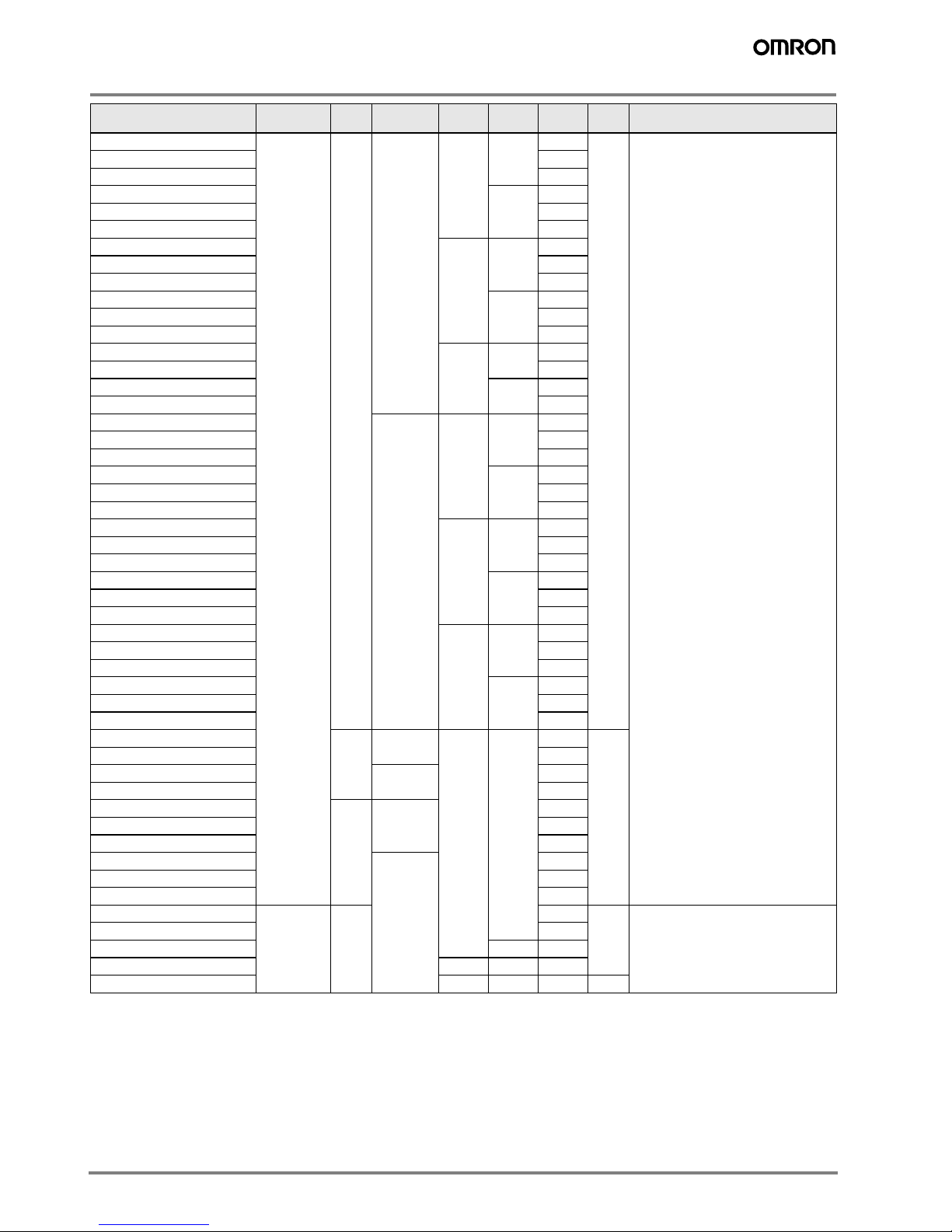
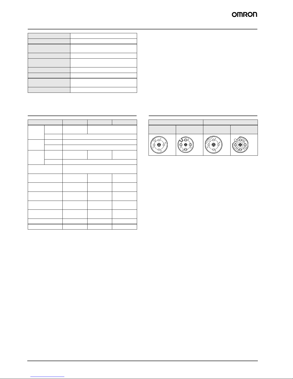
XS2F-@42@-@@0-A Connectors with Standard Cable (2, 3 or 4 wires)
XS2F-@42@-@@0-R Connectors with Vibration-proof Robot Cable
Ordering Information
Cable type Cable
connection
direction
No. of
cable
cores
Core
diameter
Cable
length
(m)
Model UL-listed
DC AC
Standard cable Straight 2 0.5 mm22 XS2F-D421-DA0-A XS2F-A421-DB0-A ---
3 XS2F-D421-DC0-A --- ---
4 XS2F-D421-D80-A XS2F-A421-D90-A Yes
2 5 XS2F-D421-GA0-A XS2F-A421-GB0-A ---
3 XS2F-D421-GC0-A --- ---
4 XS2F-D421-G80-A XS2F-A421-G90-A Yes
2 10 XS2F-D421-JA0-A XS2F-A421-JB0-A ---
3 XS2F-D421-JC0-A --- ---
4 XS2F-D421-J80-A XS2F-A421-J90-A Yes
L-shaped
(angled)
2 2 XS2F-D422-DA0-A XS2F-A422-DB0-A ---
3 XS2F-D422-DC0-A --- ---
4 XS2F-D422-D80-A --- Yes
2 5 XS2F-D422-GA0-A XS2F-A422-GB0-A ---
3 XS2F-D422-GC0-A --- ---
4 XS2F-D422-G80-A --- Yes
2 10 XS2F-D422-JA0-A XS2F-A422-JB0-A ---
3 XS2F-D422-JC0-A --- ---
4 XS2F-D422-J80-A --- Yes
Vibration-proof
robot cable
Straight 2 2 XS2F-D421-DA0-R XS2F-A421-DB0-R ---
4 XS2F-D421-D80-R XS2F-A421-D90-R ---
2 5 XS2F-D421-GA0-R XS2F-A421-GB0-R ---
4 XS2F-D421-G80-R XS2F-A421-G90-R ---
2 10 XS2F-D421-JA0-R XS2F-A421-JB0-R ---
4 XS2F-D421-J80-R XS2F-A421-J90-R ---
L-shaped
(angled)
2 2 XS2F-D422-DA0-R XS2F-A422-DB0-R ---
4 XS2F-D422-D80-R --- ---
2 5 XS2F-D422-GA0-R XS2F-A422-GB0-R ---
4 XS2F-D422-G80-R --- ---
2 10 XS2F-D422-JA0-R XS2F-A422-JB0-R ---
4 XS2F-D422-J80-R --- ---

A-10 Standard Photoelectric Sensors
Specifications
Note: 1 .The contact resistance of the connector.
2 .The dielectric strength of the connector.
Materials and Finish
Note: The T-joint of the XS2R is aluminum/white.
Socket Appearance
Note: The AC and DC connectors are different as shown here and therefore
cannot be connected together.
Rated current 3 A
Rated voltage 125 VDC, 250 VAC
Contact resistance 40 mΩmax. (20 mV max., 100 mA max.)
(See note 1).
Insulation resistance 1,000 MΩmin. (at 500 VDC)
Dielectric strength 1,500 VAC for 1 min (leakage current:
1 mA max.) (See note 2).
Degree of protection IP67 (IEC529)
Insertion tolerance 200 times min.
Assembled fixture
strength
Tensile: 98 N/15 s
Torsion: 0.98 N·m/15 s
Ambient temperature Operating: -25°C to 70°C
Item XS2F XS2R XS2C/XS2G
Con-
tacts
Materials Phosphor
bronze Brass
Finish Nickel base, 0.4-μm gold plating
Fixtures Materials Brass (See note 1.)
Finish Nickel plated (See note 1.)
Pin
Block
Materials PBT resin
(UL94V-0)
PA resin
(UL94V-0)
PBT resin
(UL94V-0)
Finish For DC: light gray; for AC: dark gray
O-ring/rubber bush-
ing Rubber
Cover Polyester
elastomer --- PBT resin
(UL94V-0)
Cap --- --- PBT resin
(UL94V-0)
Cable clamp --- --- PA resin
(UL94V-0)
Pin clamp --- --- PBT resin
(UL94V-0)
Lock spring --- --- LCP resin
(UL94V-0)
Watertight bushing --- --- Rubber
Ring --- --- Steel
DC type AC type
Male contacts Female
contacts Male contacts Female
contacts

A-11XS2
XS2
Dimensions
Straight Connectors
L-shaped Connectors
Wiring Diagram
Item
Standard cable
Vibration-proof robot cable
XS2F-@42@-@@0-A
XS2F-@42@-@@0-R
Two-core model
Three-core model
Four-core model
DC AC
5 dia. 5 dia.
14.9dia.
6 dia.
L50
5
40.7 30
DC AC
5 dia. 5 dia.
6 dia.
Brown
Blue
(DC)
Cable lead colors
Contact
No.
Brown
Blue
(AC)
Cable lead colors
Contact
No.
Brown
Blue
Black
(DC)
Cable lead colors
Contact
No.
White
Brown
Blue
Black
(DC/AC)
Cable lead colors
Contact
No.

A-12 Standard Photoelectric Sensors
5-wire Connectors for DC
XS2F-D521-@G0-A
Ordering Information
Dimensions
Straight Connectors
Cable connection
direction No. of cable cores Cable core cross-
sectional area Cable length (m)
DC
Model
Straight 5 0.3 mm22 XS2F-D521-DG0-A
5 XS2F-D521-GG0-A
5 dia.
M12 45°
14.9dia.
18
48
34
L
6 dia.
30
50
5
Note: Use the XS2F-D521-@G0-A in combination
with the XS2H-D521-@G0-A.
Brown
Blue
Cable lead colors
Contact No.
Gray
White
Black
Wiring Diagram Pin Arrangements (Engagement Side)

A-13XS2
XS2
XS2 Connector Covers
Water-resistive Covers
XS2Z-11
XS2Z-12
The Water-resistive Cover ensures IP67. When mounting the Water-resistive Cover to a Connector, be sure to apply a torque range between 0.39
and 0.49 N·m to tighten the Water-resistive Cover.
Ordering Information
Note: Orders are accepted in multiples of the minimum order.
Dust Covers
XS2Z-13
The Dust Cover is for dust prevention and does not ensure IP67 degree of protection. When mounting the Dust Cover to a connector, be sure to
press the Dust Cover onto the Connector until the Connector is fully inserted into the Dust Cover.
XS2Z-15/XS1Z-14
Ordering Information
Note: Orders are accepted in multiples of the minimum order.
Model Minimum order Material
Suitable connector
Model Mounting portion
XS2Z-11
50 Brass/nickel plated
XS2R M12 male screw
XS2Z-12 XS2R/XS2F/XW3B M12 female screw (thread bracket)
Model Minimum
order Material
Suitable connector
Model Mounting portion
XS2Z-13
50
Transparent polyvinyl chloride XS2R M12 male screw
XS2Z-14
Red polyvinyl chloride XS2R/XS2F/XW3B
Pin block (female pins)
XS2Z-15 M12 female screw (thread bracket)
M12 male screwXS2Z-11
M12
M12 x 1.0 female screw
(thread bracket)
M12XS2Z-12
M12 male screw
XS2Z-13
M12 female screw
(thread bracket)
Pin block (female pins)
XS2Z-15 XS2Z-14

A-14 Standard Photoelectric Sensors
M8 Small Size and Robot Cable Connectors
XS3F
Model Number Legend
Use this model number legend to identify products from their model number. When ordering, use a model number from the table in
Ordering Information.
1. Fastening Method
M: M8
S: S8
2. Connector Poles
4: 4 poles
3. Cable Connection Direction
1: Straight
2: L-shaped
4. Connections
4: Brown White Blue Black
5. Cable Length
01: 1 m
02: 2 m
05: 5 m
6. Cable Specifications
A: Standard cable
R: Vibration-proof robot cable
Ordering Information
M8 Model
S8 Model
1234
XS3F - @42@- 4@@ - @
56789
Pin No.
1234
Item Cable connection
direction
No. of cable
cores
Cable core
cross-
sectional area
Cable length (m) Model
Standard cable
Straight
4
0.2 mm2
2 XS3F-M421-402-A
5 XS3F-M421-405-A
L-shaped 2 XS3F-M422-402-A
5 XS3F-M422-405-A
Vibration-proof robot
cable
Straight
4
1 XS3F-M421-401-R
2 XS3F-M421-402-R
5 XS3F-M421-405-R
L-shaped
1 XS3F-M422-401-R
2 XS3F-M422-402-R
5 XS3F-M422-405-R
Cable connection
direction
No. of cable
cores Cable core cross-sectional area Cable length (m) Model
Straight
40.2 mm2
1 XS3F-S421-401-R
2 XS3F-S421-402-R
5 XS3F-S421-405-R
L-shaped
1 XS3F-S422-401-R
2 XS3F-S422-402-R
5 XS3F-S422-405-R

A-15XS3
XS3
Specifications
Note: 1 . The contact resistance of the connector.
2 .The dielectric strength of the connector.
Materials and Finish Pin Arrangement (Engaged Side)
Rated current 1 A
Rated voltage 125 VDC
Contact resistance 40 MΩmax. (20 mV max., 10 mA max.)
(See note 1.)
Insulation resistance 1,000 MΩmin. (at 500 VDC)
Dielectric strength 1,000 VAC for 1 min (leakage current:
1 mA max.) (See note 2.)
Degree of protection IP67 (IEC529)
Insertion tolerance 200 times
Cable tensile strength 50 N/15 s)
Ambient temperature Operating: -25°C to 70°C
Pin Block PBT resin/light gray or black
Contacts Brass/nickel base, 0.4-μm gold plating
Thread bracket (M8)
Shell (S8) Brass/nickel plated
Cover Thermoplastic elastomer/black
O-ring Rubber
DC
Plug Socket

A-16 Standard Photoelectric Sensors
Dimensions
M8 Screw-on cable connectors
Wiring Diagram
4 dia.
Straight Connectors
L-shaped Connectors
4 dia.
9dia.
12
34
2.15
1.95 0.5 31
2
4
3.4
M8
9dia.
12.9
L
21.5
31.4
5
30
50
White
Brown
Blue
Black
Cable lead colors
Contact No.

A-17XS3
XS3
Dimensions
M8 Snap-in cable connectors
Wiring Diagram
Straight Connectors
L-shaped Connectors
4 dia.
4 dia.
2.15
2
1
4
3
3.4
0. 5
1.95
L
30.7
21.1
13.9
50
5
30
2.15
3.4
0.5
1.95
8.2 dia.
19.8
1
3
2
4
23.1
L5 0
5
30
White
Brown
Blue
Black
Cable lead colors
Contact No.

A-18 Standard Photoelectric Sensors
Precautions
Refer to Correct Use for precautions for individual products.
Correct Use
Connections
• The XS3 and XS2 Sensor I/O Connectors cannot be connected to
each other.
• When using Sensors with Connectors or Limit Switches, use the
Sensor I/O Connectors specified in the catalog.
• Do not connect M8 screw models and S8 snap-in models together,
otherwise the proper degree of protection of the Connectors will not
be maintained.
Connector Connection and Disconnection
• Before connecting or disconnecting Connectors, make sure that no
power is being supplied to the Connectors.
• When connecting or disconnecting Connectors, be sure to hold the
Connectors by hand.
• Do not touch the engagement side of any Connector with wet
hands. If there is any water on the Connector or near the Connec-
tor, be sure to wipe off the water before connecting or disconnect-
ing the Connector, otherwise the Connector may short-circuit
internally or not ensure good insulation.
• Make sure that engagement side of any Connector is free of metal
dust or power.
• Do not use pliers to tighten mounting the thread bracket, otherwise
the thread bracket may be damaged. Be sure to tighten each
thread bracket by hand within a torque of 0.3 and 0.4 N·m. If the
thread bracket is not tightened securely, the Connector may not
maintain its proper degree of protection or the thread bracket may
fall off due to vibration.
• Fully insert S8 snap-in models until the Connectors are hidden by
the metal casing of the opposite parts, otherwise the Connectors
will not maintain their proper degree of protection or the thread
brackets may drop off due to vibration.
Cable Wire Color
• The M8/S8 Sensor I/O Connectors use the following lead wire col-
ors.
Degree of Protection
• Do not impose external force continuously on the joints of pin
blocks and covers, otherwise the Connectors may not keep its
proper degree of protection (i.e., IP67).
• Connectors are not fully watertight. Do not use them underwater.
• The Connectors are not oil-resistant. Do not use them where they
would be subject to oil.
• If Connectors are used in places with vibration or shock, secure the
engaged side of each Connector, otherwise the Connectors may
be disconnected or fail to maintain their proper degree of protec-
tion.
• Connectors are of resin mold construction. Do not impose exces-
sive force on them.
Storage
Do not store Connectors for long periods of time in the following
locations
• Locations subject to dust or high humidity
• Locations subject to ammonia gas or sulfide gas
Model Pin No.
1 2 3 4
DC 8-mm-dia.
DC4
Brown White Blue Black

Accessories
A-19Accessories
Connector terminal boxes and extended wiring accessories
Overview
Note: 1 . Please contact your OMRON representative for these models
Shape Product
group Type Housing
material Features Key
specifications
Order
reference
Applicable
Sensors
Extended wiring accessories
M12 I/O connec-
tor terminal
boxes
- PBT case
- brass
connectors
-flatsize
-forM12
connectors
- 4, 6 or 8 contacts
per box
-4A/port
- 10 or
30 V DC
- 4 or 5-pin
-IP67
XW3B
for all sensors
connected via M12
4-pin connections &
cables
I/O connector
terminal boxes
for bus
connection
Please contact your OMRON representative for our large portfolio of remote I/O
Waterproof
cover for M12
I/O connector
brass
water proof cover
for IP67 rating of
X3WB
XS2Z-12
M12 T-joint and
Y-joint plugs
- PVC cable
- brass nut
- daisy chain
model for ’AND’
configurations
(T-joint)
- direct wiring
models for ’OR’
configurations
(Y-joint)
- bifurcate mod-
els for signal
splitting
- aggregate mod-
els for reduced
wiring
- 3 A rated
current
-DC
-4-pin
-IP67
XS2R
- sensors with
built-in M12 4-pin
connector (-M1)
- sensors with M12
4-pin cable end
connector (-M1J)
M8 Y-joint plugs
- PBT case
- brass
connectors
- direct wiring
models for ’OR’
configurations
- aggregate mod-
els for reduced
wiring
- 1 A rated
current
-125VDC
-4-pin
-IP67
XS3R
- sensors with built
in M8 4-pin
connector (-M3)
- sensors with M8
4-pin cable end
connector
12

A-20 Standard Photoelectric Sensors
M12 Connector Terminal Boxes
XW3B
Materials and Finish
Note: The positive power supply, negative power supply, and ground lines are
AWG18. Signal lines are AWG22.
Ratings and Characteristics
Note: 1 . The contact resistance of the Connector.
2 .The dielectric strength of the Connector.
Compatible Connectors *1
Note: 1 .Please refer to seperate datasheet X073-E1-01 for these models.
Item Part name Materials and finish
Connectors
Anchor Brass/nickel plated
Contacts Brass/nickel base, 0.4-μm gold plat-
ing
Cable Cable
Sheath color: gray
Core size: AWG18/AWG22
(See note.)
Case
Case PBT resin (UL94V-0)/light gray
Bushing Rubber
PCB Glass-epoxy board
Seal resin Urethane resin
Rated current 4 A/port (signal lines)
12 A/box (power lines)
Rated voltage 10 to 30 VDC
Contact resistance 40 MΩmax. (with 100 mA max.,
20 mV max.) (See note 1.)
Insulation resistance 100 MΩmin. (at 500 VDC)
Dielectric strength 500 VAC for 1 min (leakage current:
1 mA max.) (See note 2.)
Degree of protection IP67 (IEC529)
Cable retention force 98 N/15 s
Insertion tolerance 200 times
Operating
temperature -25 to 70°C
XS2G Connector Plug Assemblies
(crimping, soldering, or screw-on)
XS2W Connectors on cable ends (Sockets or Plugs)
XS2H Connectors on one cable end (Plugs)
This manual suits for next models
92
Table of contents
Other Omron Cables And Connectors manuals

Omron
Omron CS1W-CIF31 User manual

Omron
Omron XN2 User manual

Omron
Omron XN2 User manual

Omron
Omron XS5H User manual

Omron
Omron XS5 User manual

Omron
Omron F3SN-A - User manual

Omron
Omron FZ-VSJ User manual

Omron
Omron ZFV-XC Series B(R)V2 User manual

Omron
Omron XS5F User manual

Omron
Omron XS5 T Series User manual
Popular Cables And Connectors manuals by other brands

Panduit
Panduit NetKey 6 Series installation instructions

Yamaichi Electronics
Yamaichi Electronics Y-Con Cover-20-TC Assembly instructions

Sennheiser
Sennheiser ASP 2 Instructions for use

Vention
Vention MO-LM-010-0001 Maintenance Guide

Philips
Philips SWV2184W Specifications

Philips
Philips SWV3544 Specifications