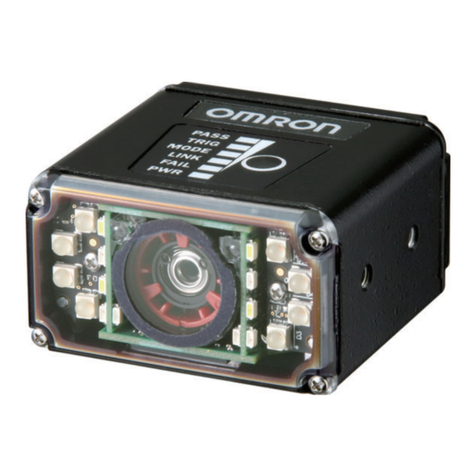
Handheld 2D Code Reader
Model
V400-H111/211/111-1
PRECAUTION ON SAFETY
Meanings of Signal Words
Indicates a potentially hazardous situation
which, if not avoided, will result in minor or
moderate injury, or may result in serious
injury or death. Additionally there may be
significant property damage.
WARNING
Meanings of Alert Symbols
A lithium battery is built into the 2D Code reader and
may occasionally combust,explode, or burn if not
treated properly.
Dispose of the Controller as industrial waste, and
never disassemble, apply pressure that would deform,
heat to 100 or higher, or incinerate the 2D Code
reader.
WARNING
This product is not designed or rated for ensring safty
of persons.
Do not use it for such purposes.
Observe the following precautions to ensure safe use of the product.
1.Installation Environment Precautions
(1)
Do not use the 2D code reader in environments with flammable
or explosive gases.
(2)Please avoid setting up in outdoor and using it.
2.Power Supply and Wiring Precautions
(1)
Use the 2D code reader with the power supply voltages specified
in this manual.
(2)Use the cables specified in this manual.
(3)
Keep the power supply cable as short as possible (10 m maximum).
(4)
Use a DC power supply with countermeasures against high-voltage
spikes (safe extra low-voltage circuits on the secondary side).
3.Other Precautions
(1)Do not attempt to disassemble, repair, or modify the 2D code
reader. Doing so may cause product failure or a fire.
(2)If abnormal odors, heating, or smoke occurs, stop using the 2D
code reader immediately,turn OFF the power, and consult with
your OMRON representative.
(3)
When disposing of the 2D code reader, treat it as industrial waste.
(4)
When disposing of the 2D code reader, do not apply pressure that
would deform.
Precaution for Safe Use
1.Environment
Do not install the product in the following locations:
(1)Locations where the ambient temperature exceeds the rated
temperature range.
(2)Locations subject to rapid changes in temperature (causing
condensation).
(3)Locations where the relative humidity exceeds the rated
humidity range.
(4)Locations subject to corrosive or flammable gases.
(5)Locations where dust, salt, or metallic powder accumulate on
the 2D code reader.
(6) Locations subject to direct vibration or impact outside the
specified ranges.
(7)Locations subject to direct sunlight.
(8)Locations subject to exposure to oil, chemicals, etc.
2.Installation and Handling of Components
(1) Use the cables and the power supply specified in this manual.
3.Attaching and Removing Cables
(1)
Do not connect a cable to the 2D Code Reader if the other end of
the cable is connected to a personal computer or a Programmable
Controller.
(2)
To prevent damage from static electricity, use a wrist strap or
another device for preventing electrostatic charges when touching
terminals or signal lines.
4.Memory Cards
(1)
Do not remove the Memory Card when the Memory Card indicator is lit.
The Memory Card or the Code Reader may be damaged.
5.Turning OFF the Power Supply
(1)
Do not turn OFF the power supply while a message is being displayed
indicating that processing is being performed. Data in memory will be
destroyed, and the 2D code reader may not operate correctly the next
time it is started.
Precaution for Correct Use
V400-AC2
Materials
PC Contact part:
Silicone Gum
(antistatic grade)
Approx.20g
Operating method
V400-AC2/AC3(CONTACTOR;OPTION)
V400-H111/211/111-1(MAIN UNIT)
Dimensions
V400-H111/211/111-1
V400-AC3
V400-H211
40 mm (Contact with the Contactor)
5VDC 10%
V400-H111
5 to 10 mm 15 to 30 mm
1A max.
RS-232C
DataMatrix ECC2000 10 10 to 64 64,
818 to 16 48
QR Code Model 1or 2 21 21 to 57 57
(Version 1 to Version 10)
Pushbutton control using the TRIGGER Button
Uploading settings by communications
command or from Memory Card.
SD Card
1.8-inch TFT liquid crystal image and read
data display.
POWER indicator
Operating: 0 to 40 ; Storage: -25 to 60
35% to 85% (with no condensation)
No corrosive gases
10 to 150 Hz; half-amplitude: 0.35 mm
(max. acceleration: 50 m
2
/s)
150 m
2
/s 3 times in 6 directions
Approx.230g
IEC60529 IP64
Case: ABS; optical surface: PC; surfaces: PMMA
Fleld of vision
Working distance
Power supply voltage
Current consumption
Serial interface
Applicable code
Operating method
Settings
Memory Card
Monitor
Indicators
Ambient temperature
Ambient humidity
Ambient environment
Vibration resistance
Shock resostance
Weight
Degree of protection
Materials
3 mm
V400-H111-1
This product is compliant with the standards below:
EN Standards(European Standards), EN61326-1
Electromagnetic environment : Industrial electromagnetic environment
(EN/IEC 61326-1 Table 2)
Also, the following condition is applied to the immunity test of this product.
: If the level of disturbance of the video is that with
characters on the monitor are readable, the test is pass.
Regulations and Standards
V400-W20-2M/W21-2M/W22-2M(CABLES;OPTION)
Operating: 0 to 40 ; Storage: -25 to 60
35% to 85% (with no condensation)
No corrosive gases
Ambient temperature
Ambient humidity
Ambient environment
Cable sheathing: Heat-resistant vinyl chloride
Special connector: PPS, PBT, POM
D-sub connector: ABS
Approx.100g
Materials
Operating method
30 mm
Minimum
bending radius
V400-W21-2MV400-W20-2M
Male,9-pin D-sub
Interface connector
Brown:+5V Blue:GND
Power Supply
Female,9-pin D-sub
V400-W22-2M
V600-A22,
(OPTION)
Approx.110g
2 Ferrite core
Accessory
Specifications
V400-AC3
PC Contact part:
POM
(White)
V400-W22-2M
V400-AC2
(Unit:mm)
64
45
55
34
225
100
MEMORYCARD
INSERT HOLE
ZOOM LEVER
LCD MONITOR OPERATING INDICATOR(GREEN)
TRIGGER SWITCH
BUZZER
LIGHTING
READING POINT
LIGHTING
4-M2 CONTACTOR
MOUNTING HOLES
V400-W20-2M/V400-W21-2M
(Unit:mm)
29.8 75
2000
20 200
30
12.6Dia.
CONNECTOR
BAND,BINDING
BUSH,CORD
VINYL INSULATED ROUND
CORD 5Dia.4CORES NAME PLATE D-SUB 9PINS
CONNECTOR
(Unit:mm)
29.8 75
2000
200
30
12.6Dia.
CONNECTOR
BAND,BINDING BUSH,CORD
VINYL INSULATED ROUND
CORD 5Dia.4CORES NAME PLATE
VINYL INSULATED FRAT
CORD 2DiaX2 2CORES
CONNECTOR
D-SUB 9PINS
CONNECTOR
(Unit:mm)
4-M2 MOUNTING SCREWS
109
43.5
100
34
40
57
(Unit:mm)
109
43.5
100
34
4-M2 MOUNTING SCREWS
57
40
The following notice applies only to products that carry the CE mark:
Notice:
This is a class A product. In residential areas it may cause radio
interference, in which case the user may be required to take adequate
measures to reduce interference.
Manufacturer:
Omron Corporation,
Shiokoji Horikawa, Shimogyo-ku,
Kyoto 600-8530 JAPA N
TRACEABILITY INFORMATION:
Importer in EU :
Omron Europe B.V.
Wegalaan 67-69
2132 JD Hoofddorp,
The Netherlands
© OMRON Corporation 2005 All Rights Reserved.
INSTRUCTION SHEET
Thank you for selecting OMRON product. This sheet
primarily describes precautions required in installing and
operating the product.
Before operating the product, read the sheet thoroughly to
acquire sufficient knowledge of the product. For your
convenience, keep the sheet at your disposal.
• Notice for Korea Radio Law
A급 기기(업무용 방송통신기자재)
이 기기는 업무용(A급) 전자파적합기기로서 판매자
또는 사용자는 이 점을 주의하시기 바라며,가정외의
지역에서 사용하는 것을 목적으로 합니다.
Suitability for Use
s
Omron Companies shall not be responsible for conformity with any standards,
codes or regulations which apply to the combination of the Product in the
Buyer’s application or use of the Product. At Buyer’s request, Omron will
provide applicable third party certification documents identifying ratings and
limitations of use which apply to the Product. This information by itself is not
sufficient for a complete determination of the suitability of the Product in
combination with the end product, machine, system, or other application or
use. Buyer shall be solely responsible for determining appropriateness of the
particular Product with respect to Buyer’s application, product or system.
Buyer shall take application responsibility in all cases.
NEVER USE THE PRODUCT FOR AN APPLICATION INVOLVING
SERIOUS RISK TO LIFE OR PROPERTY WITHOUT ENSURING THAT THE
SYSTEM AS A WHOLE HAS BEEN DESIGNED TO ADDRESS THE RISKS,
AND THAT THE OMRON PRODUCT(S) IS PROPERLY RATED AND
INSTALLED FOR THE INTENDED USE WITHIN THE OVERALL
EQUIPMENT OR SYSTEM.
See also Product catalog for Warranty and Limitation of Liability.
Oct, 2014
D
OMRON Corporation Industrial Automation Company
Contact: www.ia.omron.com
Tokyo, JAPAN
OMRON ELECTRONICS LLC
2895 Greenspoint Parkway, Suite 200
Hoffman Estates, IL 60169 U.S.A.
Tel: (1) 847-843-7900/Fax: (1) 847-843-7787
OMRON ASIA PACIFIC PTE. LTD.
No. 438A Alexandra Road # 05-05/08 (Lobby 2),
Alexandra Technopark,
Singapore 119967
Tel: (65) 6835-3011/Fax: (65) 6835-2711
OMRON (CHINA) CO., LTD.
Room 2211, Bank of China Tower,
200 Yin Cheng Zhong Road,
PuDong New Area, Shanghai, 200120, China
Tel: (86) 21-5037-2222/Fax: (86) 21-5037-2200
OMRON EUROPE B.V.
Sensor Business Unit
Carl-Benz-Str. 4, D-71154 Nufringen, Germany
Tel: (49) 7032-811-0/Fax: (49) 7032-811-199
Regional Headquarters
