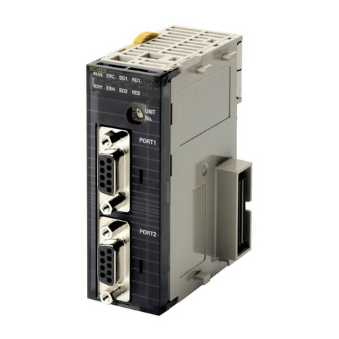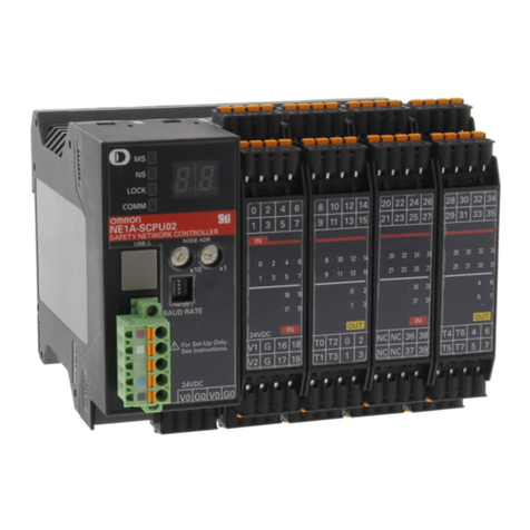
ID System ID Controller
Safety Precautions
Indicates a potentially hazardous situation which,
if not avoided, could result in death or serious
injury. Additionally, there may be severe property
damage.
WARNING
WARNING
This product is not designed for use in directly or indirectly
detecting human bodies in safety-related applications. Do not
use the product as a sensing device for human protection.
2.Installation
・The product uses the 13.56MHz frequency band to communicate with Tags. Some
devices, such as some motors, inverters, and switch mode power supplies,
generate electromagnetic waves (i.e., noise) that can affect communications with
the Tags. If any of these devices are nearby, communications with Tags may be
affected or Data Carriers may be destroyed. If the product is to be used near such
devices, check the effects on communications before using the product.
・
To minimize the general influence of noise, follow the following precautions:
(1) Ground the earth terminal of this product and any metallic material located
around the product to 100ȍor less.
(2) Keep product wiring away from high voltage or heavy current.
・The product does not provide a water-proof structure. Do not use it where mists
are present.
・Do not use chemicals that will affect product materials.
・Tighten screws to 1.2 N·m when mounting the product.
・Communications performance may be reduced due to mutual interference if more
than one Read/WriteAntenna is installed in the same vicinity. Refer to the
Read/WriteAntenna and Tag Operation Manual (Cat. No. Z248-E1) and confirm
that there is no mutual interference between Read/Write Antennas.
3.Storage
Do not store the product in the following locations.
・Locations subject to corrosive gases, dust, dirt, metal powder, or salt
・Locations where the specified ambient storage temperature range is exceeded
・Locations subject to extreme temperature changes that may result in condensation
・Locations where the specified ambient storage humidity range is exceeded
・Locations where the product would be directly subjected to vibration or shock
exceeding specifications
・Locations subject to contact with water, oil, or chemical
4.Cleaning
・Do not use thinners for cleaning. Resin materials and the case coating will be
dissolved by thinners,benzenes,acetones and kerosenes.
Precautions for Safe Use
Observe the following precautions to ensure safe usage of the product.
1. Do not use the product in environments subject to inflammable, explosive, or
corrosive gases.
2. Do not disassemble, repair, or modify the product in any way.
3. Tighten the base mounting screws and terminal block screws securely.
4. Use the specified sizes of crimp terminals for wiring.
5. Always lock the lock mechanisms on any devices provided with them, such as
cable connector lock screws.
6. Confirm that the DC power supply is within the rated power supply voltage (24
VDC +10%/-15%) before using it.
7. Do not reverse polarity when connecting the power supply.
8. Do not allow water to enter or insert wire in the gaps of the case. Fire or electric
shock may result.
9. Always turn OFF the power supply to the ID Controller before attaching or
removing the Antenna and Amplifier section.
10.If you suspect that anything is wrong with the product at any time, stop using it
immediately, turn OFF the power supply, and consult with your OMRON
representative.
11. When disposing of the product, dispose of it as industrial waste.
Model
V680-CA5D01-V2
Definition of Precautionary Information
Warning
Precautions for Correct Use
1. Installation Location
Do not install the product in the following locations:
・Locations subject to corrosive gases, dust, dirt, metal powder, or salt
・Locations where the specified ambient operating temperature range is exceeded
・Locations subject to extreme temperature changes that may result in condensation
・Locations where the specified ambient operating humidity range is exceeded
・Locations where the product would be directly subjected to vibration or shock
exceeding specifications
・Locations subject to contact with water, oil, or chemicals
■General Specifications
Item Specification
Power supplyvoltage
(power consumption,
current consumption)
24 VDC (-15% to +10%) (15 W max.,0.8A max.)
Ambient operating
temperature -10 to +55 °C (with no icing)
Between power supply terminals and GR/Case
Between GR and terminals
Insulation
resistance
Ambient operating
humidity 25% to 85% (with no condensation)
Dielectric strength
Vibration resistance
Shock resistance
Dimensions 105 x 90 x 65 mm (excluding protrusions)
Degree of protection
In-panel (equivalent to IP20)
Materials PC + ABS
Weight Approx. 300 g
Installation method DIN Rail or M4 screws
Antenna Connections V680-CA5D01-V2:1channel, V680-CA5D02-V2:2 channels
Ambient storage
temperature -25 to +65 °C (with no icing)
Ambient storage
humidity 25% to 85% (with no condensation)
10 to 150 Hz with 0.2mm double amplitude and 15m/s2
maximum acceleration, 10 sweeps of 8 minutes each in three
directions
150 m/s2
20 M
(at 500 VDC mega)
Two, 4.5-dia. mounting holes
65
(08 )
18.715
805 90
95
105
5
7.5
■Dimensions
■External I/O Specifications
●
Input Specifications
(RST, TRG1, and TRG2)
Input impedance
Input current
ON voltage
2.2 kȍ
10 mA typical (24 VDC)
19 V min.
Input voltage
24 VDC +10%
(including ripple) /-15%
(PNP or NPN)
OFF voltage
I/O response time
5 V max.
70 ms max.
●
Output Specifications
(RUN, BUSY/OUT3, ERROR/OUT4,
OUT1 and OUT2)
Leakage current
Residual voltage
ȝA max.
2.0 V max.
Maximum
switching
capacity
24 VDC +10% (including ripple)
-15%
The CPU will stop operation and the RST indicator
will light when the RST input is turned ON. The
ERROR output will be reset at that time.
100mA photo MOS outputs (PNP or NPN)
Note 1:
The transistor may be damaged if an output is shorted
with no load connected.
2:
95±0.2
2.0±08
Two, M4
Mounting Hole Dimensions
A
B
When mounting the ID
Controller to DIN Rail, hook
the ID Controller at point A
and then press in direction B.
To remove the ID Controller
from the DIN Rail, pull out
the mounting hook.
Recommended DIN Rail: PFP-100N2
(rail length: 1 m)
(manufactured by OMRON)
When mounting directly to a control panel, always use flat washers and M4 screws.
Tightening torque: 1.2 N·m
■Installation Methods
●Mounted on a Panel
●MountingtoDINRail
(1)
(2)
●I/O Device Wiring Example
Ɣ3/&2XWSXW8QLW
Ɣ131 Transistor
Open-collector
Output
(e.g., from a 3-wire
Sensor)
Ɣ&RQWDFW2XWSXW
(e.g., Pushbutton
Switch)
(e.g., C200H-OD21
or C500-OD412)
24-VDC
power
supply
+V
OUT
0 V(COM)
+V
0 V
Output
RST
TRG1
TRG2
ID Controller Input Section
COM_I
2.2 kW
2.2 kW
2.2 kW
lanretnI stiucric
Ɣ3/&,QSXW8QLW
Ɣ5HOD\
(e.g. C200H-ID212
or C500-ID218)
COM
IN
IN
RUN
BUSY/OUT3
ERROR/
OUT4
OUT1
OUT2
COM_O
・Inputs
・Outputs
lanretnI stiucric
lanretnI stiucric
lanretnI stiucric
rosneS lanretni stiucric
+
lanretnI stiucric
lanretnI stiucric
ID Controller Input Section
lanretnI stiucric
lanretnI stiucric
lanretnI stiucric
lanretnI stiucric
lanretnI stiucric
24-VDC
power
supply
+
Between power supply terminals and GR/Case
Between GR and terminals 1,000VAC
50/60Hz for 1 minute.
V680-CA5D02-V2
■Applicable Standards
1.
UL Standards
UL (Underwriters Laboratories Inc.) conditions have been met.
UL508
Use the product connected to one of the following two circuits.
(1) Limited Voltage/Current Circuit (Approved in UL508)
A circuit that uses as its power supply the secondary coil of an insulated
transformer that satisfies the following conditions:
・Maximum voltage (with no-load): 30 Vrms (42.4 V peak) OR
・Maximum current: (1) 8 A(including when shorted) OR
(2) A current restricted by a circuit protective device
(e.g., fuse) with the following ratings
No-load voltage (V peak)
0 to 20
Maximum current rating (A)
5.0
Over 20 to 30 100
Peak voltage
(2)A circuit with a maximum voltage of 30 Vrms (42.4 V peak) that uses as its
power supply a Class 2 power supply defined in UL1310 or a Class 2
transformer defined in UL1585.
2.
EMC Standards
The repuirements of the EC Directive have been satisfied.
EMC Directives::EN 61000-6-2.EN 61000-6-4
Manufacturer:
Omron Corporation,
Shiokoji Horikawa, Shimogyo-ku,
Kyoto, 600-8530 JAPAN
TRACEABILITY INFORMATION:
Importer in EU :
Omron Europe B.V.
Wegalaan 67-69
2132 JD Hoofddorp,
The Netherlands
Notice:
This is a class A product. In residential areas it may cause radio
interference, in which case the user may be required to take adequate
measures to reduce interference.
©OMRON Corporation 2007 All Rights Reserved.
INSTRUCTION SHEET
Thank you for selecting OMRON product. This sheet pri-
marily describes precautions required in installing and
operating the product.
Before operating the product, read the sheet thoroughly to
acquire sufficient knowledge of the product. For your con-
venience, keep the sheet at your disposal.
・Notice for Korea Radio Law
A급 기기(업무용 방송통신기자재)
이 기기는 업무용(A급) 전자파적합기기로서 판매자
또는 사용자는 이 점을 주의하시기 바라며,가정외의
지역에서 사용하는 것을 목적으로 합니다.
Suitability for Use
s
Omron Companies shall not be responsible for conformity with any standards,
codes or regulations which apply to the combination of the Product in the
Buyer’s application or use of the Product. At Buyer’s request, Omron will
provide applicable third party certification documents identifying ratings and
limitations of use which apply to the Product. This information by itself is not
sufficient for a complete determination of the suitability of the Product in
combination with the end product, machine, system, or other application or
use. Buyer shall be solely responsible for determining appropriateness of the
particular Product with respect to Buyer’s application, product or system.
Buyer shall take application responsibility in all cases.
NEVER USE THE PRODUCT FOR AN APPLICATION INVOLVING
SERIOUS RISK TO LIFE OR PROPERTY WITHOUT ENSURING THAT THE
SYSTEM AS A WHOLE HAS BEEN DESIGNED TO ADDRESS THE RISKS,
AND THAT THE OMRON PRODUCT(S) IS PROPERLY RATED AND
INSTALLED FOR THE INTENDED USE WITHIN THE OVERALL
EQUIPMENT OR SYSTEM.
See also Product catalog for Warranty and Limitation of Liability.
Oct, 2014
D
OMRON Corporation Industrial Automation Company
Contact: www.ia.omron.com
Tokyo, JAPAN
OMRON ELECTRONICS LLC
2895 Greenspoint Parkway, Suite 200
Hoffman Estates, IL 60169 U.S.A.
Tel: (1) 847-843-7900/Fax: (1) 847-843-7787
OMRON ASIA PACIFIC PTE. LTD.
No. 438A Alexandra Road # 05-05/08 (Lobby 2),
Alexandra Technopark,
Singapore 119967
Tel: (65) 6835-3011/Fax: (65) 6835-2711
OMRON (CHINA) CO., LTD.
Room 2211, Bank of China Tower,
200 Yin Cheng Zhong Road,
PuDong New Area, Shanghai, 200120, China
Tel: (86) 21-5037-2222/Fax: (86) 21-5037-2200
OMRON EUROPE B.V.
Sensor Business Unit
Carl-Benz-Str. 4, D-71154 Nufringen, Germany
Tel: (49) 7032-811-0/Fax: (49) 7032-811-199
Regional Headquarters
