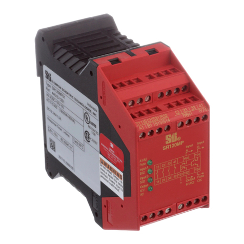
Omron Sti SR201 A User manual

Operating Instructions for SR201A Safety Monitoring Relay
1 / 6
Safety relay for monitoring EMERGENCY STOP circuits
according to EN 418 / EN 60204-1
Module de surveillance pour circuits d'ARRET D'URGENCE
selon EN 418 / EN 60204-1
Überwachungsbaustein für NOT AUS Kreise
gemäß EN 418 / EN 60204-1
Dimensions / Encombrements / Maße
Terminal marking / Repérage des bornes / Klemmenanzeiger
Function
The supply voltage, as marked on the device nameplate, is applied to the
N.C. contacts of the EMERGENCY STOP button(s) to A1/A2 (see wiring
diagram). The N.C. contacts from each of the devices connected to safety
outputs 13-14, 23-24 and 33-34 must be wired in the feedback circuit
between terminals Y1 and Y2, in series with the START button. This
assures that the device can only be started if these external contactors
have dropped out after a preceding EMERGENCY STOP command.
If the EMERGENCY STOP button is deactivated the LED “A1/A2” is lit.
The actuation of the START button energizes the internal relays K1 and
K2. The three safety outputs (13-14, 23-24 and 33-34) and the transistor
output Y43-Y44 are switched. In this state of operation, both LEDs “A1/
A2” and “K1/K2” are lit. The actuation of the EMERGENCY STOP
button(s) instantaneously opens the output contacts and the two LEDs will
go out.
Safety systems are comprised of many components. No one safety
component will insure the safety of the system. The design of the
complete safety system should be considered before you begin. It is very
important to follow applicable safety standards when installing and wiring
these components.
There are no user serviceable components in the module. Approved
safety devices must use only the hard contacts outputs between
terminals 13-14, 23-24 and 33-34. The contactless signalling circuit
between terminals Y43-Y44 is permissable only for non-safety related
functions.
22,5 mm
(0.89 in)
114 mm
(4.48 in)
99 mm
(3.89 in)
SR201A
13
A1
23 24 33
A2
14
K1/K2
TYPE
SR201A
A1/A2
Fuse
S33S34 S39
S12
S11
S11
S12
K1
K2
13 23
14 24
33
34
34
S22
35mm
(1.38 in)
R
SR201A
SR201A
A1
14
13
24
23
Y1
33
Y2
A1
A2
14
PE
24
Y43 Y44
34
SR201
!Note
Safety
Technology
& Innovation
SR201A

R
Operating Instructions for SR201A Safety Monitoring Relay
2 / 6
It is imperative that an external fuse be connected as shown on the
"WIRING DIAGRAM FOR MODULE SR201A SAFETY RELAY". For
maximum protection of the outputs, please refer to "TECHNICAL DATA"
(page 5/6).
The following wiring diagram has been tested and tried carefully under
actual service conditions. This module must be used for safety-related
functions in conjunction with the connected safety equipment and devices
that meet applicable standard requirements. A residual risk will remain if:
a) it is necessary to modify this recommended circuit and if the added/
modified components are not properly integrated in the control circuit.
b) the user does not follow the required standards applicable to the
operation of the machine, or if the adjustments to and maintenance of
the machine are not properly made. It is essential to strictly follow the
prescribed machine maintenance schedule.
c) the devices connected to the safety outputs do not have
mechanically-linked contacts.
Fonction
La tension d'alimentation conforme à la valeur marquée sur la plaque
signalétique est appliquée à travers les contacts "O" du (ou des) bouton(s)
ARRET D'URGENCE à A1/A2. Les contacts "O" des relais, intercalés à
la suite des sorties doivent être insérés dans la boucle de retour entre les
bornes Y1 et Y2, en série avec le bouton MARCHE. Par cette mesure le
démarrage de l'appareil n'est possible que si les relais, liés à la sécurité,
sont retombés au repos après avoir reçu une commande d'arrêt
d'urgence.
Si l'ARRET D'URGENCE est désactivé, la DEL “A1/A2” est allumée.
L'appui sur le bouton MARCHE commande les relais internes K1 et K2 et
active les trois sorties libres de potentiel (13-14, 23-24 et 33-34) ainsi que
la sortie statique Y43-Y44. Dans cet état de fonctionnement, les DEL's
“A1/A2” et “K1/K2” sont allumées. L'appui sur le(s) bouton(s) ARRET
D'URGENCE entraîne instantanément l'ouverture des circuits de sortie et
l'extinction des deux DEL's.
Le module ne contient pas de composants soumis à maintenance par
l'utilisateur. Pour l'autorisation d'un circuit de sécurité selon EN 60204-1 /
EN 418 il est impératif d'utiliser seulement les circuits de sortie libres de
potentiel entre les bornes 13-14, 23-24 et 33-34. L'utilisation du circuit de
signalisation sans contact entre les bornes Y43-Y44 est seulement
admissible pour des fonctions n'étant pas liées à la sécurité.
Le schéma de raccordement proposé ci-dessous a été vérifié et testé
avec le plus grand soin dans des conditions de mise en service. Des
risques subsistent si :
a) le schéma de câblage ci-dessous est modifié par changement des
connexions ou l'ajout de composants lorsque ceux-ci ne sont pas ou
insuffisamment intégrés dans le circuit de sécurité.
b) l'utilisateur ne respecte pas les exigences des normes de sécurité
pour le service, le réglage et la maintenance de la machine. Il est
important de respecter strictement les échéances de contrôle et de
maintenance.
Funktion
Die Versorgungsspannung wird gemäß angegebenen Wert auf dem
Typenschild über die Öffner der(s) NOT AUS-Taster(s) an A1/A2
angeschlossen. In den Rückführkreis zwischen den Klemmen Y1 und Y2,
in Reihe mit der START-Taste, sind die Öffnerkontakte der den
Ausgangskanälen nachgeschalteten Relais einzuschleifen. Dadurch
gelingt eine Einschaltung des Gerätes nur dann, wenn die
nachgeschalteten Relais, welche sicherheitsrelevante Funktion haben,
nach einem vorausgegangenen NOT-AUS Befehl abgefallen waren.
Bei unbetätigtem NOT-AUS leuchtet die Led “A1/A2”. Mit Betätigung der
START-Taste werden die internen Relais K1 und K2 aktiviert und die drei
potentialfreien Ausgangskanäle (13-14, 23-24, 33-34) sowie der
Transistorausgang Y43-Y44 schalten durch. Dieser Betriebszustand wird
durch die leuchtenden Led's “A1/A2” und “K1/K2“ angezeigt. Mit
Betätigung der der(s) NOT AUS-Taster(s) öffnen die Ausgangskreise
unverzögert und beide LED's verlöschen.
Das Gerät enthält keine vom Anwender zu wartenden Bauteile. Zur
Freigabe eines Sicherheitsstromkreises gemäß EN 60204-1 / EN 418 sind
ausschließlich die potentialfreien Ausgangskreise zwischen den
Klemmen 13-14, 23-24 und 33-34 zu verwenden. Der kontaktlose
Meldekreis Y43-Y44 ist lediglich für nicht sicherheitsgerichtete Aufgaben
zulässig.
Der nachstehende Schaltungsvorschlag wurde mit größter Sorgfalt unter
Betriebsbedingungen geprüft und getestet. Er erfüllt mit der
angeschlossenen Peripherie sicherheitsgerichteter Einrichtungen und
Schaltgeräte insgesamt die einschlägigen Normen. Restrisiken
verbleiben wenn:
a) vom vorgeschlagenen Schaltungskonzept abgewichen wird und
dadurch die angeschlossenen sicherheitsrelevanten Geräte oder
Schutzeinrichtungen möglicherweise nicht oder nur unzureichend in
die Sicherheitsschaltung einbezogen werden.
b) vom Betreiber die einschlägigen Sicherheitsvorschriften für Betrieb,
Einstellung und Wartung der Maschine nicht eingehalten werden. Hier
sollte auf strenge Einhaltung der Intervalle zur Prüfung und Wartung
der Maschine geachtet werden.
!Residual Risk (EN 292-1, article 5)
FAILURE TO PROTECT
• Wire safety relay using wiring diagrams provided.
• Wire to meet applicable standards requirements.
• All devices connected to the safety outputs must have mechanically-linked contacts.
• It is imperative that properly sized external fuses be connected as shown in wiring
diagrams provided.
• Strictly follow prescribed maintenance schedule when making adjustments to and
maintenance of machine.
Failure to follow these instructions can result in death or serious injury.
!WARNING
!Information complémentaire
!Risques résiduels (EN 292-1, article 5)
!Ergänzender Hinweis
!Restrisiken (EN 292-1, Punkt 5)
3 / 6
R
Operating Instructions for SR201A Safety Monitoring Relay
Wiring diagram for SR201A
Schéma de câblage de SR201A
Anschlußplan für SR201A
!DANGER
HAZARDOUS VOLTAGE
• Disconnect all power supplying ≥30V AC or 42V DC
before working on equipment.
Electric shock will result in death or serious injury.
ESC
S2
S1
K5K4
K4
K5
L1 (+)
N(–)
F1
(3)
Y1
A2 PE
A1 1323
14 24
Y2
K2
K1
K2
33
34
Y43
Y44
SR201A
+
–
LOGIC
K1
A1/A2 K1/K2
K4
K5
K4
K5
K4
K5
T
(1) (2)
+24VDC
ESC +24V DC
S2
L1(+)
N (–)
F1
(3)
Y1
A2 PE
A11323
1424
Y2
K2
K1
K2
33
34
Y43
Y44
SR201A
+
–
LOGIC
K1
A1/A2 K1/K2
F4
(3)
F3
(3)
F2
(3)
T
S1
(1) (2)
ESC =
External start conditions
Conditions de démarrage externes
Externe Startbedingungen
(1) =
3 Safety outputs
3 Sorties de sécurité
3 Sicherheitskreise
(2) =
1 Transistor output
1 Sortie statique
1 Transistorausgang
(3) =
See Technical Data for maximum fuse
sizes (page 5/6)
Voir caractéristiques techniques pour le
calibre maximal des fusibles (page 5/6)
Siehe technische Daten für max. Sicherung
(Seite 5/6)
S2 =
Start Button
Bouton marche
Starttaste
only on
48V/115V/230Va unit
seulement à
48V/115V/230Va
nur bei
48V/115V/230Va
S1=
EMERGENCY STOP - push button with two NC contacts
(recommended appl.)
Bouton poussoir d'ARRET D'URGENCE doté de 2 contacs à ouverture
(application conseillèe)
NOT AUS - Taster mit zwei Öffnerkontakten
(empfohlene Verwendung)
only on
48V/115V/230Vaunit
seulement à
48V/115V/230Va
nur bei
48V/115V/230Va
S1=
EMERGENCY STOP - push button with one NC contact
Bouton d'ARRET D'URGENCE doté d'un contact à ouverture
NOT AUS - Taster mit einem Öffnerkontakt
S2 =
Start Button
Bouton marche
Starttaste

4 / 6
R
Operating Instructions for SR201A Safety Monitoring Relay
System diagnostics LEDs on the front cover
Diagnostic du système à l'aide des DEL dans le couvercle du boîtie
Systemdiagnose mittels LED-Anzeige im Gehäusedeckel
Arrangement of LEDs in the cover
Disposition des DEL dans le couvercle du
boîtier
Anordnung der Leuchtdioden im
Gehäusedeckel
LED 1: (A1/A2)
Supply voltage is present on terminals
A1/A2.
LED 2: (K1/K2)
LED 2 indicates that the outputs between
terminals 13-14, 23-24 and 33-34 are closed.
DEL 1: (A1/A2)
Présence tension aux bornes A1/A2.
DEL 2: (K1/K2)
DEL 2 indique l’état fermé des sorties de
sécurité entre les bornes 13-14, 23-24 et
33-34.
LED 1: (A1/A2)
Versorgungsspannung an den Klemmen
A1/A2 ist vorhanden.
LED 2: (K1/K2)
LED 2 signalisiert den geschlossenen Zustand
der Sicherheitsausgänge zwischen den
Klemmen 13-14, 23-24 und 33-34.
1 A1/A2
2 K1/K2
Functional Diagram SR201A
Diagramme fonctionel du SR201A
Funktionsdiagramm SR201A
Emergency Stop A1 (NC1)
Arrêt d’urgence A1 (O1)
Not - Aus A1 (Ö)
Emergency Stop A2 (NC2)
Arrêt d’urgence A2 (O2)
Not - Aus A2 (Ö)
Feedback loop (Y1-Y2)
Boucle de retour (Y1-Y2)
Rückführkreis (Y1-Y2)
Output 13-14 (NO)
Sortie 13-14 (F)
Ausgang 13-14 (S)
Output 23-24 (NO)
Sortie 23-24 (F)
Ausgang 23-24 (S)
Output 33-34 (NO)
Sortie 33-34 (F)
Ausgang 33-34 (S)
Transistor output Y43-Y44 (NO)
Sortie statique Y43-Y44 (F)
Transistorausgang Y43-Y44 (S) Legend
Légende
Legende
On
Activé
Ein
Off
Désactivé
Aus
Supply On
Tension
d’alimentation
Supply On
dectivated
non actionné
unbetätigt
activated
actionné
betätigt
Emergency Stop Deactivated
Arrêt d’urgence non actionné
Not - Aus unbetätigt
Emergency Stop
Activated
Arrêt d’urgence
actionné
Not - Aus betätigt
Start Button
Bouton marche
Starttaste

5 / 6
R
Operating Instructions for SR201A Safety Monitoring Relay
Electrical life of the output contacts determined by EN 60947-5-1 / table C2
Durée de vie des contacts de sortie selon EN 60947-5-1 / tableau C2
Lebensdauer der Ausgangskontakte gemäß EN 60947-5-1 / Tabelle C2
100
10
1
AC15: 230V
AC1: 230V
DC1: 24V
DC13: 24V
10
4
10
5
10
6
10
7
Operation Cycles
Cycles de manoeuvre
Schaltspiele
Nominal Operating Current x 0.1A
Courant de commutation x 0,1 A
Schaltstrom x 0,1 A
TECHNICAL DATA
- Connection wires
SR201A
Single wire connection
Without cable end:
solid 0.2-2.5 mm
2
(24-14 AWG)
stranded 0.2-2.5 mm
2
(24-14 AWG)
Flexible with cable end
(without plastic sleeve): 0.25-2.5 mm
2
(24-14 AWG)
(with plastic sleeve): 0.5-2.5 mm
2
(22-14 AWG)
Multiple-wire connection (2 wires max.)
Without cable end:
solid 0.2-1 mm
2
(24-18 AWG)
stranded 0.2-1.5 mm
2
(24-16 AWG)
Flexible with cable end
(without plastic sleeve): 0.25-1 mm
2
(24-18 AWG)
Flexible with TWIN-cable end
(with plastic sleeve): 0.5-1.5 mm
2
(22-14 AWG)
CARACTERISTIQUES TECHNIQUES
- Raccordement
SR201A
Connection un fil
Sans embout:
rigide 0,2-2,5 mm
2
flexible 0,2-2,5 mm
2
Flexible avec embout
(sans colleret plastique): 0,25-2,5 mm
2
(avec colleret plastique): 0,25-2,5 mm
2
Connection deux fils
Sans embout:
rigide 0,2-1 mm
2
flexible 0,2-1,5 mm
2
Flexible avec embout
(sans colleret plastique): 0,25-1 mm
2
Flexible avec embout TWIN
(avec colleret plastique): 0,5-1,5 mm
2
TECHNISCHE DATEN
- Anschlußquerschnitte
SR201A
Einzelleiteranschluß
Ohne Aderendhülse:
starr 0,2-2,5 mm
2
flexibel 0,2-2,5 mm
2
Flexibel mit Aderendhülse
(ohne Kunststoffhülse): 0,25-2,5 mm
2
(mit Kunststoffhülse): 0,25-2,5 mm
2
Mehrleiteranschluß (2 Leiter max.)
Ohne Aderendhülse:
starr 0,2-1 mm
2
flexibel 0,2-1,5 mm
2
Flexibel mit Aderendhülse
(ohne Kunststoffhülse): 0,25-1 mm
2
Flexibel mit TWIN-Aderendhülse
(mit Kunststoffhülse): 0,5-1,5 mm
2

Scientific Technologies Inc.
6550 Dumbarton Circle, Fremont CA 94555-3605 USA
©2003 STI Literature PN99429-0010
R
6 / 6
R
Operating Instructions for SR201A Safety Monitoring Relay
- Mounting:
Mounting on 35 mm DIN rail
according to DIN EN 50022
- Degree of protection according to IEC 529:
Terminals: IP20
Enclosure: IP40
- Weight:
Version 115V+230V a0.21 kg (7.4 oz)
Version 48V a0.21 kg (7.4 oz)
Version 24V z0.16 kg (5.6 oz)
- Mounting position: any plane
- Ambient operating temperature:
-10˚ C to +55˚ C (+ 14˚ F to +130˚ F)
- Overvoltage category III (4 kV)
Pollution degree 2
Rated insulation voltage 300V
according to DIN VDE 0110 / part 1+2
- Supply voltage U
E
according to IEC 38:
230V a- 50/60 Hz (+10% / -15%)
115V a- 50/60 Hz (+15% / -15%)
48V a- 50/60 Hz (+10% / -15%)
24V a- 50/60 Hz (+10% / -20%)
24V c(+20% / -20%)
(refer to device nameplate for supply voltage)
Max. protection: 4 A fuse (gL)
- Power consumption:
Version 230V a≤2.1 VA
Version 115V a≤2.3 VA
Version 48V a≤2.1 VA
Version 24V a≤2.2 VA
Version 24V c≤1.2 W
-Safety outputs:
13-14, 23-24, 33-34
Category 3 according to EN 954-1
- The sum of simultaneous currents on all of
the outputs is limited to:
ΣIth ≤10.5 A
- Protection of outputs:
max.: 4 A fuse (gL) or 6A fastblow
- Maximum switching capacity of outputs:
AC 15 - C300 (1800VA/180VA)
DC 13 24V/2A - L/R=50ms
- Transistor output, NO
(contactless):Y43-Y44
(Typically: 24V/20mA)
- Response time: ≤100 ms
- Minimum switching ratings of outputs:
The device is capable to switch low voltage
loads (min. 17 V/10 mA) provided that the
contact has never been used with higher
loads.
- Fixation du boîtier:
Encliquetage sur profile chapeau 35 mm
selon DIN EN 50022
- Degré de protection selon IEC 529:
Bornes: IP20
Boîtier: IP40
- Poids:
Version 115V+230V a0,21 kg
Version 48V a0,21 kg
Version 24V z0,16 kg
- Position de montage: indifférente
- Température de fonctionnement:
- 10˚ C / + 55˚ C
- Catégorie de surtension III (4kV)
Degré de pollution 2
Tension assignée d’isolement 300V
selon DIN VDE 0110 / partie 1+2
- Tension d’alimentation U
E
selon IEC 38:
230V a- 50/60 Hz (+10% / -15%)
115V a- 50/60 Hz (+15% / -15%)
48V a- 50/60 Hz (+10% / -15%)
24V a- 50/60 Hz (+10% / -20%)
24V c(+20% / -20%)
(voir plaque signalétique)
Protection max.: 4 A gL
- Puissance consommée:
Version 230V a≤2,1 VA
Version 115V a≤2,3 VA
Version 48V a≤2,1 VA
Version 24V a≤2,2 VA
Version 24V c≤1,2 W
-Sorties de sécurité (libre de potentiel):
13-14, 23-24, 33-34
Catégorie 3 selon EN 954-1
- Limite de courants cumulés (charge
simultanée des plusieurs circuits de sortie):
ΣIth ≤10,5 A
- Protection des sorties:
max.: 4 A gL Ou 6A rapide
- Capacité de coupure maxi des sorties:
AC 15 - C300 (1800VA/180VA)
DC 13 24V/2A - L/R=50ms
- Sortie statique, “F”
(sans contact):Y43-Y44
(Typiquement: 24V/20mA)
- Temps de réponse: ≤100 ms
L'appareil est aussi capable de commuter des
charges faibles (17V / 10mA minimum) à
condition que le contact n'ait jamais commuté
de forte charge auparavant, car la couche d'or
revêtant le contact pourrait être altérée.
- Gehäusebefestigung:
Schnappbefestigung auf 35 mm
Normschiene nach DIN EN 50022
- Schutzart gemäß IEC 529:
Klemmen: IP20
Gehäuse: IP40
- Gewicht:
Version 115V+230V a0,21 kg
Version 48V a0,21 kg
Version 24V z0,16 kg
- Einbaulage: beliebig
- Umgebungstemperatur im Betrieb:
- 10˚ C / + 55˚ C
- Überspannungskategorie III (4 kV)
Verschmutzungsgrad 2
Bemessungsisolationsspannung 300V
gemäß DIN VDE 0110 / Teil 1+2
- Anschlußspannung U
E
gemäß IEC 38:
230V a- 50/60 Hz (+10% / -15%)
115V a- 50/60 Hz (+15% / -15%)
48V a- 50/60 Hz (+10% / -15%)
24V a- 50/60 Hz (+10% / -20%)
24V c(+20% / -20%)
(Siehe Typenschild)
Absicherung max.: 4 A gL
- Eigenverbrauch:
Version 230V a≤2,1 VA
Version 115V a≤2,3 VA
Version 48V a≤2,1 VA
Version 24V a≤2,2 VA
Version 24V c≤1,2 W
-Sicherheitsausgänge (potentialfrei):
13-14, 23-24, 33-34
Kategorie 3 gemäß EN 954-1
- Summenstrombegrenzung bei gleichzeitiger
Belastung mehrerer Ausgangskreise:
ΣIth ≤10,5 A
- Absicherung der Ausgangskreise:
max.: 4 A gL oder 6A Flink
- Max. Schaltleistung der Ausgangskanäle:
AC 15 - C300 (1800VA/180VA)
DC 13 24V/2A - L/R=50ms
- Transistorausgang Schließerfunktion
(kontaktlos):Y43-Y44
(Typisch: 24V/20mA)
- Ansprechzeit: ≤100 ms
Das Gerät ist ebenfalls zum Schalten von
Kleinstlasten (min. 17V / 10mA) geeignet. Dies
ist jedoch nur dann möglich, wenn bisher über
diesen Kontakt keine höheren Lasten
geschaltet wurden, da hierdurch die
Kontaktvergoldung abgebrannt sein könnte.
6 A 2 A 2 A
4 A 4 A 2 A
3,5 A 3,5 A 3,5 A
6 A 2 A 2 A
4 A 4 A 2 A
3,5 A 3,5 A 3,5 A
6 A 2 A 2 A
4 A 4 A 2 A
3,5 A 3,5 A 3,5 A

OMRON CANADA, INC. • HEAD OFFICE
Toronto, ON, Canada • 416.286.6465 • 866.986.6766 • www.omron247.com
OMRON ELECTRONICS DE MEXICO • HEAD OFFICE
México DF • 52.
55.59.01.43.00
OMRON ELECTRONICS DE MEXICO • SALES OFFICE
OMRON ELETRÔNICA DO BRASIL LTDA • HEAD OFFICE
São Paulo, SP, Brasil • 55.11.2101.6300 • www.omron.com.br
OMRON ARGENTINA • SALES OFFICE
Cono Sur • 54.11.4783.5300
OMRON CHILE • SALES OFFICE
Santiago • 56.9.9917.3920
OTHER OMRON LATIN AMERICA SALES
54.11.4783.5300
Authorized Distributor:
J95I-E-01 10/05 Note: Specifications are subject to change. © 2014 Omron Electronics LLC Printed in U.S.A.
Printed on recycled paper.
Automation Control Systems
• Machine Automation Controllers (MAC) • Programmable Controllers (PLC)
• Operator interfaces (HMI) • Distributed I/O • Software
Drives & Motion Controls
• Servo & AC Drives • Motion Controllers & Encoders
Temperature & Process Controllers
• Single and Multi-loop Controllers
Sensors & Vision
• Proximity Sensors • Photoelectric Sensors • Fiber-Optic Sensors
• Amplified Photomicrosensors • Measurement Sensors
• Ultrasonic Sensors • Vision Sensors
Industrial Components
• RFID/Code Readers • Relays • Pushbuttons & Indicators
• Limit and Basic Switches • Timers • Counters • Metering Devices
• Power Supplies
Safety
• Laser Scanners • Safety Mats • Edges and Bumpers • Programmable Safety
Controllers • Light Curtains • Safety Relays • Safety Interlock Switches
OMRON AUTOMATION AND SAFETY • THE AMERICAS HEADQUARTERS • Chicago, IL USA • 847.843.7900 • 800.556.6766 • www.omron247.com
OMRON EUROPE B.V. •
Wegalaan 67-69, NL-2132 JD, Hoofddorp, The Netherlands.
•
+31 (0) 23 568 13 00
•
www.industrial.omron.eu
Table of contents
Other Omron Relay manuals

Omron
Omron G3PA-VD Series User manual

Omron
Omron K8AK-TH User manual

Omron
Omron G9SA - User manual

Omron
Omron K8DT-AW Series User manual

Omron
Omron G7J - User manual

Omron
Omron G70D-SOC08 User manual

Omron
Omron K8AB-PA1 User manual

Omron
Omron K6EL User manual

Omron
Omron G9SX-EX401 Series User manual

Omron
Omron G9SA - User manual

Omron
Omron K8AK-AW Series User manual

Omron
Omron K8AB-PA1 User manual

Omron
Omron Sti SR101A Operation manual

Omron
Omron K8AK-VW2 User manual

Omron
Omron K8AK-VW2 24 VAC/DC User manual

Omron
Omron G9SE-201 User manual

Omron
Omron G9SA - User manual

Omron
Omron K8AB-AS User manual

Omron
Omron G3PA-450B-VD-2 User manual

Omron
Omron J7TKN - User manual