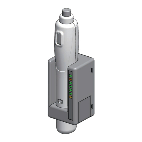
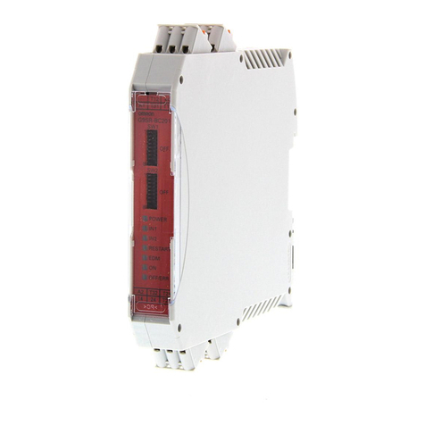
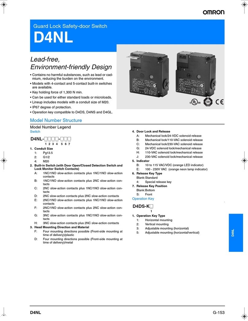
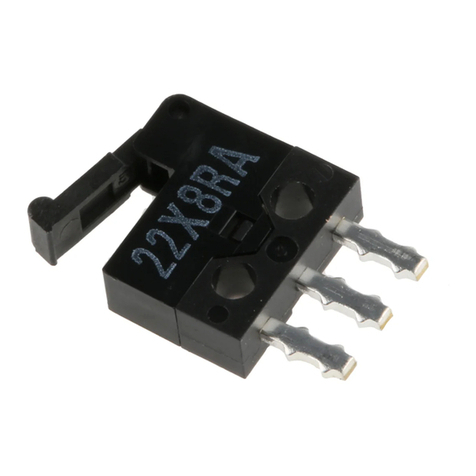
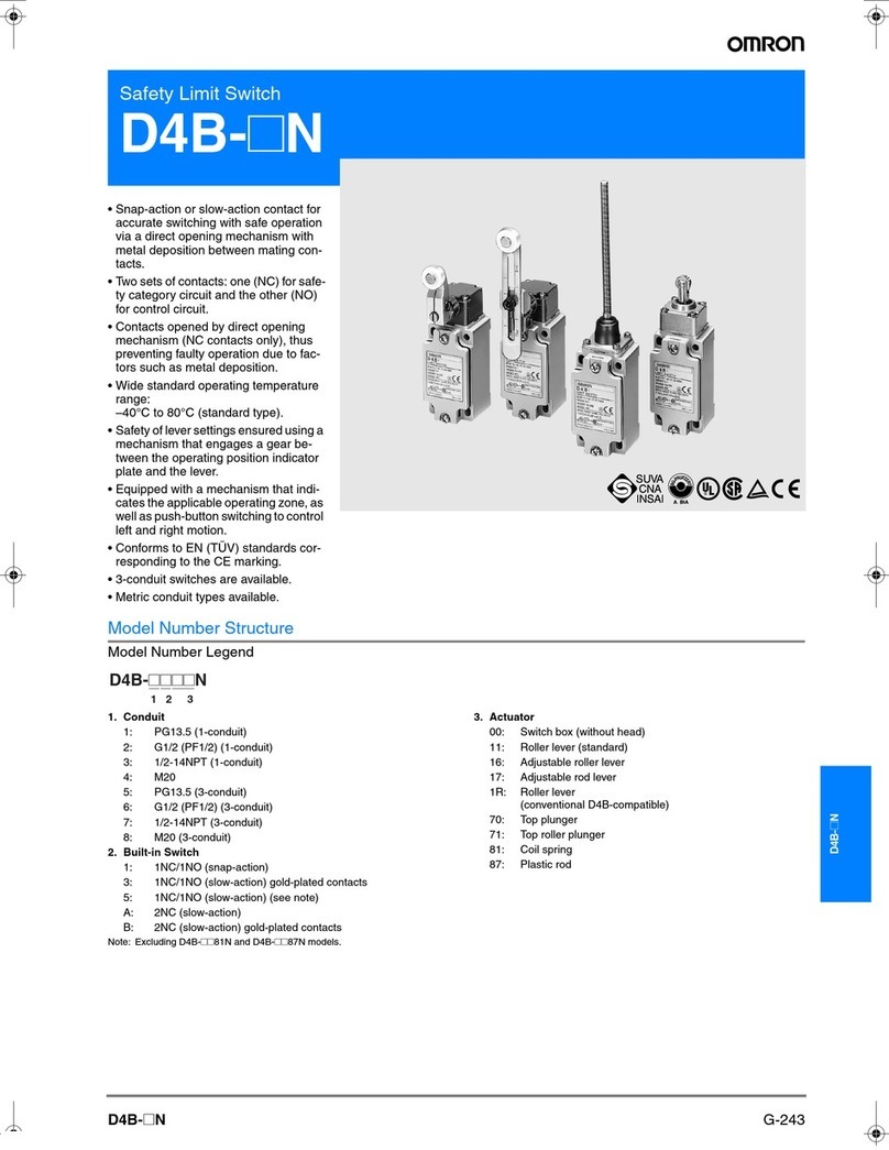
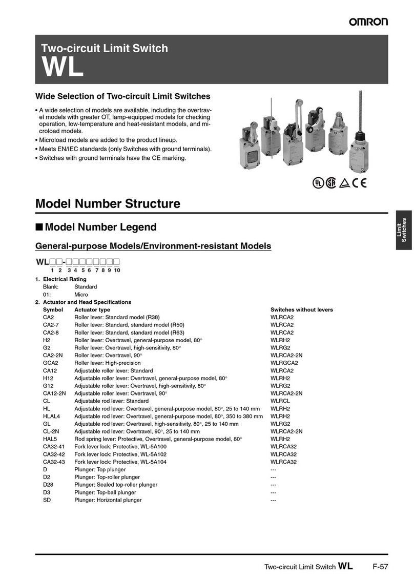
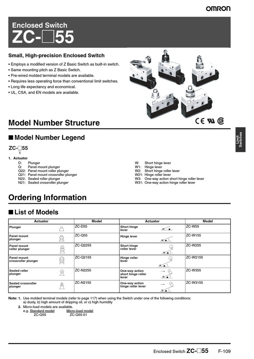
Omron G9SX Series User manual

NEW
D40A/G9SX-NS
Compact Non-Contact Door Switch/
Flexible Safety Unit
Stable Operation Increases Line Efficiency

New Type of Non-Contact Door Switches for
Worker Safety and Higher Productivity
These new Non-Contact Door Switches provide more stability in detection than
previously possible with non-contact door switches.
●Easy-to-see 2-Color Indicators
●Small Actuator
Solves Conventional Switch Issues to Provide Stable Detection
The Switch does not accurately detect the door when it is closed slowly, resulting in an error.
The D40A does not use reed switches and
provides stable detection with electronic switches.
Conventional Switches
Detects slow rotating operation.
Compact
Switch status is easy to see at a glance with
these red/yellow LED indicators.
An actuator that is smaller than the switch saves
space, even inside the door.
Even when mounted with an L-bracket, the
actuator's height will not hinder installation or
operation.
Red:
Open door
detected.
Yellow:
Closed door
detected.
Not lit:
Power OFF
or failure
Switch Actuator
Issue 1 Is
Solution 1 So
Conventional switch
Door
closed
slowly.
An error can occur
if the door is closed
slowly with
conventional
switches.
Slow
Magnet
Reed switch contacts Reed switch contacts
Magnet
ErrorError
If the switching timing of
reed switch contacts 1
and 2 varies too much,
the Controller detects an
error and turns OFF the
output to maintain safety.
Note: The figure is intended
only as an illustration.
Stable Detection
with the D40A's
New System
Slow
Detects slow lateral operation.

●Mount from Either Side
●Connect Up to 30 Switches to a Single Controller
rror.
With the D40A...
eration.
Mount from
Either Side
Up to 30 Switches
Mount from whichever side provides the easiest wiring
path to enable mounting to all types of doors.
Reduce costs by connecting up to 30 Switches to a single Controller.
It is nearly impossible to tell which door is open in a multi-door application.
Issue 2
Solution 2
Error
Swinging doorsSwinging doors Sliding doorsSliding doors
If an error occurs...
The auxiliary outputs can be used to easily indicate which door is
open.
And with two-color indicators, mounting adjustments are also easy.
The D40A is the first Non-contact Door Switch to combine 2-color
indicators, auxiliary outputs, and 30-switch connection capacity,
allowing you to create a better safety environment.
It's impossible to tell if there is a door open or if an error has occurred.
The system cannot be started because the Controller has turned
OFF the output even though all doors appear to be closed.
All doors must be opened and closed before operation can be
started.

Two Types of Controller to Solve Productivity,
Expandability, and Maintenance Issues
●Two Different Controllers
Reduce Costs with these New-Concept Controllers
Two Controllers are required for emergency stop switches and
non-contact door switches.
The G9SX-NS and G9SX-NSA are designed specifically for use with the
D40A, and with the G9SX-NSA you can also connect mechanical safety
door switches. Among other features, these Controllers support logical
AND connections that enable partial stops. These Controllers make the
most of D40A Switches.
Issue 1
G9SX-NS
@D40A input
@Two instantaneous
safety outputs
@Logical AND
connection output
@Logical AND
connection input
G9SX-NSA
@D40A plus mechanical
safety door switch input,
channel 1 or 2
@Two instantaneous safety
outputs
@Two OFF-delay safety
outputs
@Logical AND
connection input
@Logical AND
connection output
●One hazard.
●The system must be stopped
when either a door is opened
or an emergency stop switch
is pressed.
The D40A
Simplifies the
Configuration
With only one G9SX-
NSA222-T03@
Controller, both a Non-
contact Door Switch
and an emergency
stop switch can be
connected.
The G9SA must be
added to connect the
emergency stop
switch.
Application
D40B-J1
Emergency
stop switch
(See note.)
G9SA
D40A
G9SX-NSA
Emergency
stop switch
(See note.)
Two
Controllers
D40B
One
Controller

●
Expansion Units to Easily Increase the Number of Outputs with the G9SX-NSA
●
Mechanical Safety Door Switches Can Also Be Connected with the G9SX-NSA
Another Controller has to be added to use an OFF-delay timer.
●Indicators That Make Maintenance Easier
Up to 25 Outputs
G9SX-EX Expansion Unit
Logical AND
connection error
Safety Door
Switches
D40A
The indicators show the
location and cause of wiring
errors and any other errors that
are detected.
Auxiliary outputs for errors also
contribute to reducing down
time.
Inputs can be accepted from
both D40A Switches and
mechanical switches to
reduce the number of
Controllers and costs.
The number of outputs can
be easily increased using
connectors.
Up to 25 outputs can be
configured.
Issue 2
Input error Output error
The G9SA must be
added to use an
OFF-delay timer.
G9SA
OFF-delay output
AB
AB
G9SA-321-T@
D40B-J1
Emergency
stop switch
(See note.)
D40A
Emergency
stop switch
(See note.)
G9SX-BC G9SX-NSA
Three
Controllers
Two
Controllers
The D40A
Simplifies the
Configuration
D40B
A Controller can be
eliminated because
the G9SX-NSA222-
T03@provides an
OFF-delay output.
Application
D40A
Note: Always use a manual reset when using an emergency stop.
Logical AND
connection
Wiring
One
Controller
●Two hazards.
●The power supply must be
turned OFF immediately when
the emergency stop switch is
pressed.
●When a door is opened, a
stop signal is sent to only
servomotor B and then the
power supply is turned OFF.

Configuration Example for Logical AND Connections with the G9SX
Segment A Segment B Segment C
Logical AND
connections
G9SX-BC
(1) Emergency stop
switch
G9SX-AD G9SX-NSG9SX-AD
(2) Door A (3) Door B (4) Door with D40A
D40A
Segment A Segment B
(1) Emergency stop switch
pressed.
Stop Stop
Segment C
Stop
Segment A Segment B
(2) Door A opened.
Stop
Segment C
Segment A Segment B
(3) Door B opened.
Stop Stop
Segment C
Stop
Segment A Segment B
(4) Door with D40A opened.
Stop Stop
Segment C
Stop
Operation Examples
Robot A Robot B
Small Assembly System
Logical AND connections
(1) Emergency stop
switch
D40A
G9SX-NS G9SX-NS
(2) Robot door A (3) Robot door B
Semiconductor Inspection System
G9SX-BC
Robot A Robot B
Stop Stop
Robot A Robot B
Stop
Robot A Robot B
Stop Stop
Operation Examples
Safety Door SwitchSafety Door Switch
D40A
Logical AND Connections
OMRON's unique logical AND connections enable easily constructing safety circuits that were troublesome with
previous Controllers. The new Non-contact Door Switch Controllers embody the concepts for the G9SX Series, so you
can also use the previous G9SX-series Controllers in the same system.
(2) Door A (with door switch) (3) Door B (with door switch)
(4) Door with
the D40A
Robot door A
Robot door B
(1) Emergency stop
switch
Segment C
Segment B
Segment A
Note: Refer to the G9SX datasheet (Cat. No. J150) and to the 2006 Safety Components Series Group Catalog (Cat. No.Y106) for details on logical AND connections and the G9SX-series Controllers.
●Both robots will stop when the emergency stop
switch is pressed.
●Robot A will stop when robot door A is opened.
●Robot B will stop when robot door B is opened.
●
The entire system will stop if the emergency stop switch is pressed.
●
Only segment A will stop if door A (with door switch) is opened.
●
Only segment B will stop if door B (with door switch) is opened.
●
Only segment C will stop if the door with the D40A is opened.
(1) Emergency stop
switch pressed.
(2) Robot door A
opened.
(3) Robot door B
opened.

Compact Non-Contact Door Switch D40A/Flexible Safety Unit G9SX-NS 7
Compact Non-Contact Door Switch/Flexible Safety Unit
D40A/G9SX-NS
Electronic Detection Mechanism for Better
Stability in Non-contact Door Switch
Operation
• Stable operation reduces Controller errors caused by unstable
doors.
• Connect up to 30 Non-contact Door Switches with LED
indicators to one Controller.
• Reversible switch provides flexibility in installation.
• Two-color LED indicator enables easier maintenance by
identification of door status and cable disconnections.
• Safety category 3 (EN 954-1).
• Both Non-contact Door Switches and conventional Key-type
Safety-door Switches can be input to one Controller, saving
space.
• OFF-delay output provided for stop category 1.
• Easily construct partial stop and complete stop systems with the
logical AND connection function, using G9SX as the Controller.
Refer to “Precautions” on page 28.
Model Number Structure
■Model Number Legend
Non-Contact Door Switch (Switch/Actuator)
Non-Contact Door Switch Controller
1. Type
1: Standard model
2. Auxiliary outputs
C: 1NO (PNP transistor output)
3. Cable length
2: 2 m
5: 5 m
123
D40A - @@@
1234 5 6
G9SX - @@@@@@ - @@@ - @@
1. Functions
NS/NSA: D40A Controller
EX: Expansion Unit
2. Output Configuration
(Instantaneous Safety Outputs)
2: 2 outputs
4: 4 outputs
3. Output Configuration
(OFF-delayed Safety Outputs)
0: None
2: 2 outputs
4. Output Configuration
(Auxiliary Outputs)
1: 1 output
2: 2 outputs
5. Max. OFF-delay Time
D40A Controller
T03: 3 s (Variable)
Expansion Unit
Blank: No OFF delay
T: OFF delay
6. Terminal Block Type
RT: Screw terminals
RC: Spring-cage terminals

8Compact Non-Contact Door Switch D40A/Flexible Safety Unit G9SX-NS
Ordering Information
Non-Contact Door Switches (Switch/Actuator)
Note: 1. Must be used in combination with a G9SX-NS@Non-contact Door Switch Controller.
2. PNP open-collector semiconductor output.
Non-Contact Door Switch Controllers (Controllers for D40A)
Note: 1. P channel MOS FET transistor output
2. The OFF-delayed output becomes an instantaneous output by setting the OFF-delay time to 0 s.
3. PNP transistor output
4. The OFF-delay time can be set in 16 steps as follows:
0/0.2/0.3/0.4/0.5/0.6/0.7/0.8/0.9/1.0/1.2/1.4/1.8/2.0/2.5/3.0 s
Expansion Units
Note: 1. PNP transistor output
2. The OFF-delay time is synchronized to the OFF-delay time setting in the connected Controller (G9SX-NSA222-T03-@).
Classification Appearance Auxiliary outputs Cable length Mode
Standard models Semiconductor outputs
(See note 2.)
2 m D40A-1C2
5 m D40A-1C5
Safety outputs
(See note.1)
Auxiliary
outputs
(See note
3.)
Logical
AND con-
nection
input
Logical
AND con-
nection
output
Max. OFF
delay time
(See note 4.)
Rated
voltage
Terminal block type Model
Instanta-
neous
OFF-delayed
(See note 2.)
2
(Semicon-
ductors)
02
(Semicon-
ductors)
1 1 --- 24 VDC Screw terminals G9SX-NS202-RT
Spring-cage terminals G9SX-NS202-RC
2
(Semiconduc-
tors)
3.0 s Screw terminals G9SX-NSA222-T03-RT
Spring-cage terminals G9SX-NSA222-T03-RC
Safety outputs Auxiliary
outputs
OFF-delay time Rated voltage Terminal block type Model
Instantaneous OFF-delayed
4PST-NO --- 1
(Semiconductor)
(See note 1.)
--- 24 VDC Screw terminals G9SX-EX401-RT
Spring-cage terminals G9SX-EX401-RC
--- 4PST-NO (See note 2.) Screw terminals G9SX-EX041-T-RT
Spring-cage terminals G9SX-EX041-T-RC

Compact Non-Contact Door Switch D40A/Flexible Safety Unit G9SX-NS 9
Specifications
■Ratings/Characteristics of Non-contact Door Switches
Note: 1. This is the distance where the switch operates from OFF to ON when approaching and the distance where the switch operates from ON
to OFF when separating when the switch and actuator target marks are on the same axis, and the sensing surfaces coincide.
2. Turns ON when the actuator is approaching.
3. For details, refer to item 5 on page 29.
Item Model D40A-1C@
Operating
characteristics
(See note 1.)
Operating distance OFF→ON 5 mm min.
Operating distance ON→OFF 15 mm max.
Differential travel (max.) 20% of operating distance
Influence of temperature (max.) ±20% of operating distance at 23°C, within temperature range of −10 to 55°C
Ambient operating temperature −10 to 55°C (no icing or condensation)
Ambient operating humidity 25% to 85%
Insulation resistance (between charged parts and case) 50 MΩmax. (at 500 VDC)
Dielectric strength (between charged parts and case) 1,000 VAC for 1 min
Vibration resistance 10 to 55 to 10 Hz (single amplitude: 0.75 mm, double amplitude: 1.5 mm)
Shock resistance 300 m/s2min.
Degree of protection IP67
Material PBT resin
Mounting method M4 screws
Terminal screw tightening torque 1 N·m
Power consumption 0.6 W max.
Auxiliary outputs (See note 2.) 24 VDC, 10 mA (PNP open-collector outputs)
LED indicators Actuator not detected (red); actuator detected (yellow)
Connection cables 2 m, 5 m
Number of connectable switches (See note 3.) 30 max. (wiring length: 100 m max.)
Weight Switch: approx. 145 g, actuator: approx. 20 g (D40A-1C2)
10 Compact Non-Contact Door Switch D40A/Flexible Safety Unit G9SX-NS
■Ratings of Non-contact Door Switch Controllers
Power input
Note: Power consumption of loads not included.
Inputs
Note: Only applies to the G9SX-NSA222-T03-@. Refers to input other than that from the Non-contact Door Switch.
Outputs
Note: 1. While safety outputs are in the ON state, the following signal sequence is output continuously for diagnosis.
When using the safety outputs as input signals to control devices (i.e. Programmable Controllers), consider the OFF pulse shown below.
2. The following derating is required when Units are mounted side-by-side.
G9SX-NS202-@/G9SX-NSA222-T03-@: 0.4 A max. load current
Expansion Unit
Item Model G9SX-NS202-@G9SX-NSA222-T03-@G9SX-EX-@
Rated supply voltage 24 V DC
Operating voltage range −15% to 10% of rated supply voltage
Rated power consumption (See note.) 3 W max. 4 W max. 2 W max.
Item Model G9SX-NS202-@/G9SX-NSA222-T03-@
Safety input (See note.) Operating voltage: 20.4 VDC to 26.4 VDC, internal impedance: approx. 2.8 kΩ
Feedback/reset input
Item Model G9SX-NS202-@/G9SX-NSA222-T03-@
Instantaneous safety output (See note 1.)
OFF-delayed safety output (See note 1.)
P channel MOS FET transistor output
Load current: 0.8 A DC max. (See note 2.)
Auxiliary output PNP transistor output
Load current: 100 mA max.
ON
OFF
360 µs max.
Approx.100 ms
Item Model G9SX-EX-@
Rated load 250 VAC, 3 A/30 VDC, 3 A (resistive load)
Rated carry current 3 A
Maximum switching voltage 250 VAC, 125 VDC

Compact Non-Contact Door Switch D40A/Flexible Safety Unit G9SX-NS 11
■Characteristics
Note: 1. When two or more Units are connected by logical AND, the operating time and response time are the sum total of the operating times
and response times, respectively, of all the Units connected by logical AND.
2. Represents the operating time when the safety input turns ON with all other conditions set.
3. Represents the operating time when the logical AND input and the Non-contact Door Switch input turn ON with all other conditions set.
4. This does not include the operating time or response time of G9SX-NS@that are connected.
5. This does not include the operating time or response time of internal relays in the G9SX-EX-@.
Item Model G9SX-NS202-@G9SX-NSA222-T03-@G9SX-EX-@
Over-voltage category
(IEC/EN 60664-1)
II II (Relay outputs 13 to 43 and 14 to
44: III)
Operating time (OFF to ON state)
(See note 1.)
100 ms max. (Logical AND
connection input ON and Non-
contact Door Switch input ON)
50 ms max. (Safety input: ON)
(See note 2.)
100 ms max. (Logical AND connection
input ON and Non-contact Door Switch
input ON) (See note 3.)
30 ms max. (See note 4.)
Response time (ON to OFF state)
(See note 1.)
15 ms max. (Logical AND
connection input: OFF)
20 ms max. (Non-contact Door
Switch input OFF)
15 ms max. (Safety input OFF and
logical AND connection input OFF)
20 ms max. (Non-contact Door Switch
input: OFF)
10 ms max. (See note 4.)
ON-state residual voltage 3.0 V max. (safety output, auxiliary output)
OFF-state leakage current 0.1 mA max. (safety output, auxiliary output)
Maximum wiring length of safety in-
put, logical AND connection input,
and Non-contact Door Switch input
100 m max. (External connection impedance: 100 Ωmax. and 10 nF max.)
Reset input time
(Reset button pressing time)
100 ms min.
Accuracy of OFF-delay time
(See note 5.)
--- Within ±5% of the set value Within ±5% of the set value
Insulation
resistance
Between logical AND
connection terminals,
and power supply input
terminals and other input
and output terminals con-
nected together
20 MΩmin. (at 100 VDC) ---
Between all terminals
connected
together and DIN rail
100 MΩmin.
(at 500 VDC)
Dielectric
strength
Between logical AND
connection terminals,
and power supply input
terminals and other input
and output terminals con-
nected together
500 VAC for 1 min. ---
Between all terminals
connected together and
DIN rail
1,200 VAC for 1 min
Between different poles
of outputs
---
Between relay outputs
connected together and
other terminals connect-
ed together
2,200 VAC for 1 min
Vibration resistance 10 to 55 to 10 Hz, 0.375-mm single amplitude (0.75-mm double amplitude)
Shock
resistance
Destruction 300 m/s2
Malfunction 100 m/s2
Durability Electrical --- 100,000 cycles min. rated load,
switching frequency: 1,800 cycles/
hour)
Mechanical --- 5,000,000 cycles min. (switching
frequency: 7,200 cycles/hour)
Ambient operating temperature −10 to 55°C (no icing or condensation)
Ambient operating humidity 25% to 85%
Terminal tightening torque 0.5 N·m (For the G9SX-NS@-RT (with screw terminals) only)
Weight Approx. 125 g Approx. 200 g Approx. 165 g

12 Compact Non-Contact Door Switch D40A/Flexible Safety Unit G9SX-NS
Logical AND Connection
Note: 1. See Logical AND Connection Combinations below for details.
2. The number of G9SX-EX401-@Expansion Units or G9SX-EX041-T-@Expansion Units (OFF-delayed Model) not included.
3. G9SX-EX401-@Expansion Units and G9SX-EX041-T-@Expansion Units (OFF-delayed Model) can be mixed.
Logical AND Connection Combinations
1. One logical AND connection output from a G9SX-NS@Controller
can be logical AND connected to up to four Controllers.
2. Any G9SX-NS@Controller that receives a logical AND
connection input can be logically connected to other Controllers
on up to five layers.
Note: The G9SX-NS@in the above diagram can be replaced by the
G9SX-AD@Advanced Unit.
For details on G9SX-AD@Advanced Units, refer to the G9SX-
series Flexible Safety Unit catalog. (Cat. No. J150).
3. The largest possible system configuration contains a total of 20
G9SX-NS@Controllers, G9SX-AD@Advanced Units, and G9SX-
BC Basic Units. In this configuration, each Controller or Advanced
Unit can have up to five Expansion Units.
Item Model G9SX-NS202-@G9SX-NSA222-T03-@G9SX-EX-@
Number of Units connected per logical
AND output
4 Units max. ---
Total number of Units connected by logical
AND (See note 2.)
20 Units max. ---
Number of Units connected in series by
logical AND
5 Units max. ---
Max. number of Expansion Units
connected (See note 3.)
--- 5 Units max.
Maximum cable length for logical AND
input
100 m max. ---
G9SX-NS@
G9SX-NS@G9SX-NS@G9SX-NS@G9SX-NS@
G9SX-NS@
G9SX-NS@
G9SX-NS@
G9SX-NS@
G9SX-NS@
G9SX-@
G9SX-AD@
or
G9SX-NS@
G9SX-AD@
or
G9SX-NS@
G9SX-AD@
or
G9SX-NS@
G9SX-AD@
or
G9SX-NS@
G9SX-AD@
or
G9SX-NS@
G9SX-AD@
or
G9SX-NS@
G9SX-AD@
or
G9SX-NS@
G9SX-AD@
or
G9SX-NS@
G9SX-AD@
or
G9SX-NS@
G9SX-AD@
or
G9SX-NS@
G9SX-AD@
or
G9SX-NS@
G9SX-AD@
or
G9SX-NS@
G9SX-AD@
or
G9SX-NS@
G9SX-AD@
or
G9SX-NS@
G9SX-AD@
or
G9SX-NS@
G9SX-AD@
or
G9SX-NS@
G9SX-AD@
or
G9SX-NS@
G9SX-AD@
or
G9SX-NS@
G9SX-AD@
or
G9SX-NS@
Number of Units connected
per logical AND output: 4
Units max.
Number of Units connected
in series by logical AND: 5
Units max. Total number of Units
connected by logical AND:
20 Units max.

Compact Non-Contact Door Switch D40A/Flexible Safety Unit G9SX-NS 13
Response Time and Operating Time
1. G9SX-NS@
2. G9SX-NSA@
3. Multiple G9SX-NS@/NSA@Non-contact Door Switch Controllers
When multiple Controllers are logically connected with AND connections, the response time is the sum of the response times given in 1 and 2
above. (It is the same for the operating time.)
Non-contact Door
Switch input
Logical AND input
Note: 1. The maximum response time is the time it takes the output to switch from ON to OFF
after the input switches from ON to OFF.
2. The maximum operating time is the time it takes the output to switch from OFF to ON
after the input switches from OFF to ON.
Max. response time
(excluding Expansion
Units) (See note 1.)
Max. operating time
(excluding Expansion
Units) (See note 2.)
Non-contact Door Switch input 20 ms 100 ms
Logical AND input 20 ms 100 ms
Note: 1. The maximum response time is the time it takes the output to switch from ON to OFF
after the input switches from ON to OFF.
2. The maximum operating time is the time it takes the output to switch from OFF to ON
after the input switches from OFF to ON.
Max. response time
(excluding Expansion
Units) (See note 1.)
Max. operating time
(excluding Expansion
Units) (See note 2.)
Non-contact Door Switch input 20 ms 100 ms
Safety input 15 ms 50 ms
Logical AND input 20 ms 100 ms
D4NS
Safety input
Logical AND input
Non-contact Door
Switch input
D40A (1)
D40A (2)
D40A (3)
D4NS
Safety input
Safety output
(1)
Safety output (2)
Safety output (3)
Logical AND
(1)
Logical AND
(2)
Case 1
Response Time from When D40A (1) Turns from ON to OFF until Safety Output (2) Turns from
ON to OFF
(
Case 2
Response Time from When D4NS Turns from ON to OFF until Safety Output (3) Turns from
ON to OFF
20 ms + 20 ms = 40 ms
(D40A (1)) (Logical AND
connection (1))
15 ms + 20 ms + 20 ms = 55 ms
(D4NS) (Logical AND
connection (1))
(Logical AND
connection (2))

14 Compact Non-Contact Door Switch D40A/Flexible Safety Unit G9SX-NS
Engineering Data
Detection Ranges (Typical Characteristics Data)
Note: 1. The operating distance is the distance between the switch and actuator sensing surfaces.
2. Data in the diagram is typical data at an ambient temperature of 23°C. Actual operating values may vary.
The operating distance may be affected by ambient metal, magnet catches, and temperature.
X
Y
Sensing surface
Tar
g
et marks
16
14
12
10
8
6
4
2
0−6−4−20 2 46
Distance from the target mark on the switch X (mm)
Operating distance Y (mm)
ON
OFF
0
2
4
6
8
10
12
14
−15 −10 −50 51015
Distance from the target mark on the switch Z (mm)
Operating distance Y (mm)
ON
OFF
ZY
Sensing surface
Target marks

Compact Non-Contact Door Switch D40A/Flexible Safety Unit G9SX-NS 15
Connections
■Internal Connection
G9SX-NS202-@(Non-contact Door Switch Controller)
Note: 1. Internal power supply circuit is not isolated.
2. Logical AND input is isolated.
3. Outputs S14 to S24 are internally redundant.
G9SX-EX401-@/G9SX-EX041-T-@
(Expansion Unit/Expansion Unit OFF-delayed Model)
Note: 1. Internal power supply circuit is not isolated.
2. Relay outputs are isolated.
G9SX-NSA222-T03-@
(Non-contact Door Switch Controller)
Note: 1. Internal power supply circuit is not isolated.
2. Logical AND input is isolated.
3. Outputs S14 to S54 are internally redundant.
■Internal Circuit Diagram
D40A-1C@
(
See note 3.
)
(See
note 2.)
Logical AND
input
Safety output control Auxiliary
output control
Reset/Feedback
Input
Non-contact Door
Switch control
Power
supply
circuit
(See
note 1.)
D1 D2
X1L1A2 X2
S24S14
D3 D4
T31 T32 T33 T41 T42
A1
A2 X2
Power
supply
circuit Auxiliary
output
control
Safety
output
control
A1
K1
13 23 33 43
14 24 34 44
K2
Exp.
sig.
IN
Exp.
sig.
OUT
(See note 1.)
(See note 2.)
A1
A2
T11
S14 S24 S44 S54
L1 X1 X2
T12 T21 T22 T31 T32 T33
Y1 D1 D2 D3 D4
T41 T42
Power
supply
circuit
(See
note 1.)
(
See note 3.
)
Safety
input 1
Safety output control Auxiliary
output control Expansion Unit
output control
Safety
input 2
Reset/Feedback
Input
Cross fault
detection
input
Logical
AND input
(See
note
2.)
Non-contact Door
Switch control
Internal circuit
Brown
Blue
White
Black
Ye l l o w

16 Compact Non-Contact Door Switch D40A/Flexible Safety Unit G9SX-NS
Dimensions
Note: All units are in millimeters unless otherwise indicated.
48
7.2 dia.
6
13
7.2 dia.
7.2 dia.
4838
Two, 4.2 dia.
12
17
9.5
7.2 dia.
38
20 Two, 4.2 dia.
25
13
(2) Indicator
Sensing surface
Sensing surface
Vinyl-insulated round cord, dia. 4,
5-conductor (conductor cross-sectional area:
0.2 mm2,Insulator diameter: 1.0 mm)
Standard length: 2 m/5 m
(2)
Non-contact Door Switch (Switch/Actuator)
D40A-1C2
D40A-1C5
(Switch)(Actuator)
No.
NS
FB
ERR
AND
EI
PWR
D4L1S24S14
A2X2T42T41
A1X1D2D1
D3T32 T33T31
G9SX-NS202
24VDC
23 max. 115 max.
100 max.
(6) (See note 3.)
(6) (See note 3.)
(22.5)(See note 1.)
FBPWR
AND
EI
NS
ERR
D4
A2
S14
T41
S24
T42
L1
X2
D3
T33T32T31
A1X1D2D1
Note: 1. Typical dimension
2. Above outline drawing is for models with spring-cage terminals (-RC).
3. For models with spring-cage terminals (-RC) only.
Terminal arrangement
Non-contact Door Switch Controller
G9SX-NS202-@
No.
OFF-DELAY
L1S54S44S24S14 D4
A2T42T41T22T21
A1X2X1Y1T12T11
T33T31
T1
ERR
EI
AND
FB
ED
T2
PWR
T32 D2 D3D1
G9SX-NSA222-T30
24VDC
NS
0.5
0.4
0.3
0.2 3.0
2.5
2.0
1.8
1.4
1.2
1.0
0.9
0.8
0.6
0.7
0
(10) 115 max.
100 max.
35.5 max.
(6) (See note 3.)
(6) (See note 3.)
(
35
)
(
See note 1.
)
FBPWR
T1
AND
EI
T2
NS
ED
ERR
S54
T41
S14
T21
S24
T22
S44
L1
T42
D4
A2
T33T32T31
X1Y1
T12T11
X2 A1
D1 D2 D3
Terminal arrangement
Non-contact Door Switch Controller
G9SX-NSA222-T03-@
Note: 1. Typical dimension
2. Above outline drawing is for models with spring-cage terminals (-RC).
3. For models with spring-cage terminals (-RC) only.

Compact Non-Contact Door Switch D40A/Flexible Safety Unit G9SX-NS 17
23 max. 115 max.
100 max.
(6) (See note 3.)
(6) (See note 3.)
(
22.5
)
(
See note 1.
)
Expansion Unit
G9SX-EX401-@
Expansion Unit (OFF-delayed Model)
G9SX-EX041-T-@
43332313
PWR
44
A2
14 24
A1
34
X2
EI
ERR
43332313
PWR
44
A2
14 24
A1
34
X2
ED
ERR
G9SX-EX041-T-@
(Expansion Unit
with OFF Delay)
G9SX-EX401-@
(Expansion Unit)
Terminal arrangement
Note: 1. Typical dimension
2. Above outline drawing is for models with spring-cage terminals (-RC).
3. For models with spring-cage terminals (-RC) only.

18 Compact Non-Contact Door Switch D40A/Flexible Safety Unit G9SX-NS
■Non-contact Door Switch and Non-contact Door Switch Controller
Wiring
Example: Wiring a Single Switch
Note: The auxiliary output load current must be 10 mA max.
Example: Wiring Multiple Switches
Connect Up to 30 Non-contact Door Switches
Wiring of Inputs and Outputs
White
G9SX-NS202-@
G9SX-NSA222-T03-@
Auxiliary output loa
d
(See note.)
D40A-1C@
D1 D2 D3 D4 A2
Black
Brown
Blue
Ye l l o w
G9SX-NS202-@
G9SX-NSA222-T03-@
White
D1 D2 D3 D4
White
White
Black
Black
Black
Brown
Brown
Brown
Blue
Blue
Blue
Signal name Wire color Description of operation
Non-contact Door Switch
power supply input
Brown Supplies power to the D40A.
Connect to the D3 or D4 terminal of the G9SX-NS@.
Blue
Non-contact Door Switch input White Inputs signals from the G9SX-NS@.
The Non-contact Door Switch input must be ON as a required condition for the Non-contact
Door Switch output to be ON.
Non-contact Door Switch
output
Black Turns ON and OFF according to actuator detection and the status of the Non-contact Door
Switch input.
Auxiliary output Yellow Turns ON when actuator is detected.

Compact Non-Contact Door Switch D40A/Flexible Safety Unit G9SX-NS 19
■Wiring of Inputs and Outputs
G9SX-NS202-@
Signal name Terminal
name
Description of operation Wiring
Power supply
input
A1, A2 Connect the power source to the A1 and A2 terminals. Connect the power supply plus (24 VDC) to the A1
terminal.
Connect the power supply minus (GND) to the A2
terminal.
Non-contact Door
Switch input
D1, D2,
D3, D4
All Non-contact Door Switch inputs connected to the
G9SX-NS@must be ON as a required condition for
the safety outputs to be ON. Otherwise the safety out-
puts cannot be in the ON state.
Feedback/reset
input
T31, T32,
T33
To set the safety outputs in the ON state, the ON state
signal must be input to T33.
Otherwise the safety outputs cannot be in the ON
state.
Auto reset
To set the safety outputs in the ON state, the signal in-
put to T32 must change from the OFF state to the ON
state, and then to the OFF state. Otherwise the safety
outputs cannot be in the ON state.
Manual reset
Logical AND
connection input
T41, T42 A logical AND connection means that one unit (Unit A)
outputs a safety signal “a” to a subsequent unit (Unit
B) and Unit B calculates the logical AND (i.e., outputs
the AND) of the signal “a” and safety signal “b”, which
is input to Unit B.
Thereby the logic of the safety output of Unit B is
(AND). (An AND of inputs “a” and “b” is output.)
To set the safety outputs of the subsequent Unit in the
ON state, its logical AND connection preset switch
must be set to AND (enable) and the high signal must
be input to T41 of the subsequent unit.
Instantaneous
safety output
S14, S24 Turns ON/OFF according to the state of the safety in-
puts, Non-contact Door Switch inputs, feedback/reset
inputs, and logical AND connection inputs.
During OFF-delay state, the Instantaneous safety out-
puts are not able to turn ON.
Keep these outputs open when not used.
Logical AND
connection output
L1 Outputs a signal of the same logic and at the same
time as the instantaneous safety outputs.
Keep these outputs open when not used.
Auxiliary monitor
output
X1 Outputs a signal of the same logic and at the same
time as the instantaneous safety outputs
Keep these outputs open when not used.
Auxiliary error
output
X2 Outputs when the error indicator is lit or flashing. Keep these outputs open when not used.
D1 D2 D3 D4
White Black Brown Blue
Feedback loop
KM
+24 V
T31 T33T32
Feedback loop
KM +24 V
T31 T33T32
Reset
Switch
G9SX-NS/NSA
L1
A2
G9SX-NS/NSA
L1
T41 T42
A2
A2
G9SX-NS/NSA
Logical AND connection sig.
(1st layer)
Next unit
(
5 la
y
ers max.
)
T41 T42
G9SX-NS/NSA
L1
T41 T42
Logical AND connection sig.
(2nd layer)
Next unit (4 unit max.)
Input b
Input a
Output (a)
Output (a&b)
Unit B
Unit A
Next unit (4 unit max.)

20 Compact Non-Contact Door Switch D40A/Flexible Safety Unit G9SX-NS
G9SX-NSA222-T03-@
■Connecting Safety Sensors
Safety sensors cannot be connected to safety inputs for the G9SX-NSA222-T03-@.
Signal name Terminal
name
Description of operation Wiring
Power supply input A1, A2 Connect the power source to the A1 and A2 terminals. Connect the power supply plus (24 VDC) to the A1 terminal.
Connect the power supply minus (GND) to the A2 terminal.
Safety input 1 T11, T12 To set the safety outputs in the ON state, the high state
signals must be input to both safety input 1 and safety
input 2. Otherwise the safety outputs cannot be in the
ON state.
Corresponds to Safety Catego-
ry 2
Corresponds to Safety Catego-
ry 3 (without short-circuit mon-
itoring between systems)
Safety input 2 T21, T22
Corresponds to Safety Catego-
ry 3 (Cross fault detecting
mode (for safety inputs))
Non-contact Door
Switch input D1, D2,
D3, D4 All Non-contact Door Switch inputs connected to the
G9SX-NS must be ON as a required condition for the
safety outputs to be ON.
Otherwise the safety outputs cannot be in the ON state.
Feedback/reset
input T31, T32,
T33 To set the safety outputs in the ON state, the ON state
signal must be input to T33.
Otherwise the safety outputs cannot be in the ON state.
Auto reset
To set the safety outputs in the ON state, the signal in-
put to T32 must change from the OFF state to the ON
state, and then to the OFF state. Otherwise the safety
outputs cannot be in the ON state.
Manual reset
Logical AND
connection input T41, T42,
T51, T52 A logical AND connection means that one unit (Unit A)
outputs a safety signal “a” to a subsequent unit (Unit B)
and Unit B calculates the logical AND (i.e., outputs the
AND) of the signal “a” and safety signal “b”, which is in-
put to Unit B.
Thereby the logic of the safety output “b” is output.)
To set the safety outputs of the subsequent Unit in the
ON state, its logical AND connection preset switch
must be set to AND (enable) and the high signal must
be input to T41 of the subsequent unit.
Cross fault
detection input Y1 Selects the mode for the failure detecting (cross fault
detecting) function for the safety inputs of G9SX corre-
sponding to the connection of the cross fault detection
input.
Keep Y1 open when using T11, T21. (Cross fault detecting mode
(for safety inputs))
Connect Y1 to 24 VDC when not using T11, T21. (Wiring
corresponding to category 2 or 3, or when connecting safety
sensors)
Instantaneous
safety output S14, S24 Turns ON/OFF according to the state of the safety in-
puts, feedback/reset inputs, and logical AND connec-
tion inputs.
During OFF-delay state, the Instantaneous safety out-
puts are not able to turn ON.
Keep these outputs open when not used.
OFF-delayed
safety output S44, S54 OFF-delayed safety outputs.
The OFF-delay time is set by the OFF-delay preset
switch.
When the delay time is set to zero, these outputs can
be used as non-delay outputs.
Keep these outputs open when not used.
Logical AND
connection output L1 Outputs a signal of the same logic and at the same time
as the instantaneous safety outputs. Keep these outputs open when not used.
Auxiliary monitor
output X1 Outputs a signal of the same logic and at the same time
as the instantaneous safety outputs. Keep these outputs open when not used.
Auxiliary error
output X2 Outputs when the error indicator is lit or flashing. Keep these outputs open when not used.
T11 T12 T21 T22
Y1
+24 V
+24 V
T11 T12 T21 T22
Y1
+24 V +24 V
+24 V
T11 T12 T21 T22
Y1
NC
D1 D2 D3 D4
White Black Brown Blue
Feedback loop
KM
+24 V
T31 T33T32
Feedback loop
KM +24 V
T31 T33T32
Reset
Switch
G9SX-NS/NSA
L1
A2
L1
T41 T42
A2
A2
G9SX-NS/NSA
Logical AND connection sig.
(1st layer)
Next unit (4 unit max.)
Next unit
(
5 la
y
ers max.
)
T41 T42
L1
T41 T42
Logical AND connection sig.
(2nd layer)
Next unit (4 unit max.)
Input b
Input a
Output (a)
Output (a&b)
Unit B
Unit A
G9SX-NS/NSA
G9SX-NS/NSA
Other manuals for G9SX Series
5
This manual suits for next models
13
Table of contents
Other Omron Switch manuals

Omron
Omron A22LK Series User manual

Omron
Omron HL-5030 User manual

Omron
Omron D5B - User manual

Omron
Omron A2W-R**-WC1 Series User manual

Omron
Omron D4BL - User manual

Omron
Omron G3M User manual

Omron
Omron A165K - User manual

Omron
Omron ER1032 User manual

Omron
Omron HL-5000 - User manual

Omron
Omron S8VS-01505 User manual
Popular Switch manuals by other brands

ORiNG
ORiNG IBS-102FX Quick installation guide

AbleNet
AbleNet Big Beamer quick start guide

steute
steute E 12 Mounting and wiring instructions

Extreme Networks
Extreme Networks Alpine 3802 Hardware installation guide

Endress+Hauser
Endress+Hauser OFTE20 operating instructions

Cisco
Cisco IE-3000-8TC Software configuration guide