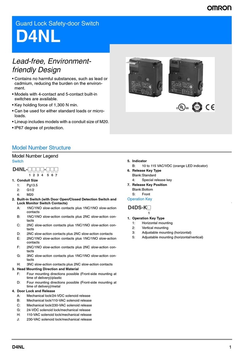
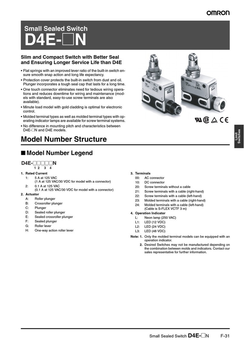
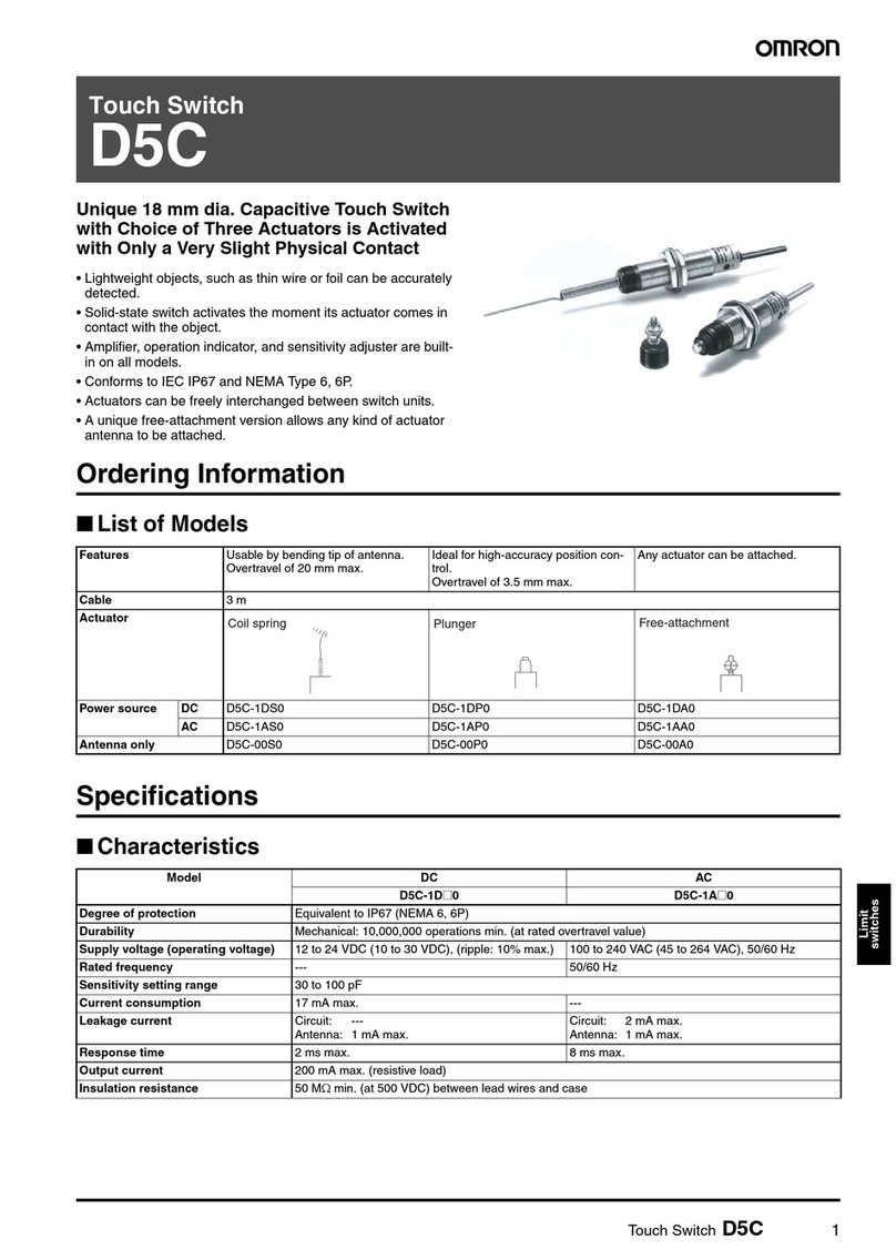
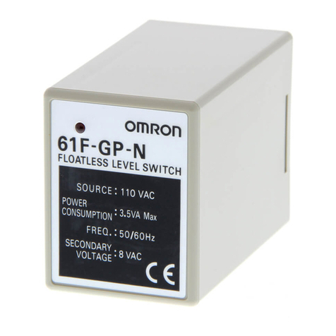
Omron ZC-55 - User manual

Enclosed Switch ZC-@55 F-109
Limit
Switches
Enclosed Switch
ZC-@55
Small, High-precision Enclosed Switch
• Employs a modified version of Z Basic Switch as built-in switch.
• Same mounting pitch as Z Basic Switch.
• Pre-wired molded terminal models are available.
• Requires less operating force than conventional limit switches.
• Long life expectancy and economical.
• UL, CSA, and EN models are available.
Model Number Structure
■Model Number Legend
1. Actuator
D: Plunger
Q: Panel mount plunger
Q22: Panel mount roller plunger
Q21: Panel mount crossroller plunger
N22: Sealed roller plunger
N21: Sealed crossroller plunger
W: Short hinge lever
W1: Hinge lever
W2: Short hinge roller lever
W21: Hinge roller lever
W3: One-way action short hinge roller lever
W31: One-way action hinge roller lever
Ordering Information
■List of Models
Note: 1. Use molded terminal models (refer to page 117) when using the Switch under one of the following conditions:
a) dusty, b) high amount of dripping oil, or c) high humidity
2. Micro-load models are available.
e.g. Standard model Micro-load model
ZC-Q55 ZC-Q55-01
1
ZC-@55
Actuator Model Actuator Model
ZC-D55 ZC-W55
ZC-Q55 ZC-W155
ZC-Q2255 ZC-W255
ZC-Q2155 ZC-W2155
ZC-N2255 ZC-W355
ZC-N2155 ZC-W3155
Plunger Short hinge
lever
Panel mount
plunger Hinge lever
Panel mount
roller plunger
Short hinge
roller lever
Panel mount
crossroller plunger
Hinge roller
lever
Sealed roller
plunger One-way action
short hinge roller
lever
Sealed crossroller
plunger
One-way action
hinge roller lever

F-110 Enclosed Switch ZC-@55
Terminal Protective Cover, Seal Rubber, and Rubber Packing
(The Switch is equipped with these 3 items as a standard.)
Specifications
■Approved Standards
(Except Molded Terminal Models and Operation Indicator-equipped Model)
■Approved Standard Ratings
UL/CSA
A300
TÜV Rheinland
250 V, 10 A (AC12)
■Ratings
Note: 1. The above figures are for steady-state currents.
2. Inductive loads have a power factor of 0.4 min. (AC) and a time constant of 7 ms max. (DC).
3. Lamp load has an inrush current of 10 times the steady-state current.
4. Motor load has an inrush current of 6 times the steady-state current.
5. The above ratings were tested under the following conditions according to JIS C4508.
Ambient temperature: 20±2°C
Ambient humidity: 65±5%
Operating frequency: 20 operations/min
Agency Standard File No.
UL UL508 E76675
CSA C22.2, No. 14 LR45258
TÜV Rheinland EN60947-1, EN60947-5-1 J9650089
Rubber packing
Terminal cover Seal rubber
•ZC Terminal Cover
(Product code: ZC55-0002H)
•ZC Seal Rubber
(Product code: SC-1404C)
•ZC Rubber Packing
(Product code: ZC55-9999G)
Voltage Carry current Current Volt-amperes
Make Break Make Break
120 VAC 10 A 60 A 6 A 7,200 VA 720 VA
240 VAC 30 A 3 A
Micro load 0.1 A, 125 VAC
0.1 A, 30 VDC
Rated voltage Non-inductive load Inductive load
Resistive load Lamp load Inductive load Motor load
NC NO NC NO NC NO NC NO
125 VAC 10 A 3 A 1.5 A 10 A 5 A 2.5 A
250 VAC 10 A 2.5 A 1.25 A 10 A 3 A 1.5 A
8 VDC 10 A 3 A 1.5 A 6 A 5 A 2.5 A
14 VDC 10 A 3 A 1.5 A 6 A 5 A 2.5 A
30 VDC 6 A 3 A 1.5 A 5 A 5 A 2.5 A
125 VDC 0.5 A 0.4 A 0.4 A 0.05 A 0.05 A 0.05 A
250 VDC 0.25 A 0.2 A 0.2 A 0.03 A 0.03 A 0.03 A
Inrush current NC 30 A max.
NO 15 A max.

Enclosed Switch ZC-@55 F-111
Limit
Switches
■Characteristics
Note: Less than 1 ms under a free state at the operating limits.
■Operating Characteristics
■Contact Form
Degree of protections IP67
Durability Mechanical: 10,000,000 operations min.
Electrical: 500,000 operations min.
Operating speed 0.05 mm to 0.5 m/s (at pin plunger)
Operating frequency Mechanical: 120 operations/min
Electrical: 20 operations/min
Insulation resistance 100 MΩmin. (at 500 VDC)
Contact resistance 15 mΩmax. (initial value)
Dielectric strength 1,000 VAC, 50/60 Hz for 1 min between non-continuous terminals
2,000 VAC, 50/60 Hz for 1 min between current-carrying metal part and ground, and between each terminal
and non-current-carrying metal parts
Rated insulation voltage (Ui)1,000 VAC
Pollution degree
(operating environment) 3 (IEC947-5-1)
Short-circuit protective device 10 A-fuse type gG (IEC 269)
Protection against electric
shock Class II
PT1 (tracking characteristics) 175
Switch category D (IEC335)
Rated operating current (Ie) 10 A
Rated operating voltage (Ue) 250 VAC
Vibration resistance Malfunction: 10 to 55 Hz, 1.5-mm double amplitude (see note)
Shock resistance Destruction: 1,000 m/s2max.
Malfunction: 300 m/s2max. (at pin plunger) (see note)
Ambient temperature Operating: –10°C to 80°C (with no icing)
Ambient humidity Operating: 35% to 95%
Weight Approx. 92 g (in case of ZC-Q22(21)55)
Model ZC-D55 ZC-Q55 ZC-Q2255 ZC-Q2155 ZC-N2255 ZC-N2155
OF max. 11.8 N 11.8 N 6.86 N
RF min. 4.90 N 4.90 N 1.67 N
PT max. 1.5 mm 1.5 mm 1.5 mm
OT min. 2.4 mm 3 mm 2.5 mm
MD max. 0.2 mm 0.2 mm 0.2 mm
OP 32.4±0.8 mm 38.2±0.8 mm 47.4±0.8 mm
Model ZC-W55 ZC-W155 ZC-W255 ZC-W2155 ZC-W355 ZC-W3155
OF max. 3.92 N 2.75 N 3.92 N 2.75 N 3.92 N 2.75 N
RF min. 0.78 N 0.59 N 0.78 N 0.59 N 0.78 N 0.59 N
OT min. 6 mm 8.4 mm 6 mm 8.4 mm 6 mm 8.4 mm
MD max. 1 mm 1.4 mm 1 mm 1.4 mm 1 mm 1.4 mm
OP 28.5±1.2 mm 28.5±1.2 mm 43±1.2 mm 43±1.2 mm 53±1.2 mm 53±1.2 mm
FP max. 34.7 mm 36.7 mm 49.2 mm 51.3 mm 59.2 mm 61.2 mm
COM NO NC
COM
NC
NO
EN60947-5-1

F-112 Enclosed Switch ZC-@55
Engineering Data
■Mechanical Durability
(for ZC-Q55)
■Electrical Durability
Nomenclature
Changing the Terminal Protective Cover around allows the cable to be pulled out from either the right or the left.
Note: M4 binding head screws (with toothed washers) are used as the terminal screws.
Durability (x 104operations)
Operating temperature: 20±2°C
Operating humidity: 65±5%
No load
Operating frequency: 120 operations/min
OT (mm)
Durability (x 104operations)
Operating temperature: 20±2°C
Operating humidity: 65±5%
Operating frequency: 20 operations/min
Switchin
g
current
(
A
)
Roller
Plunger
Case
NC fixed contact
Moving contact
NO fixed contact
Seal rubber
Switch
Packing
Terminal
Protective
Cover Common
terminal
(COM)
Normally
open
terminal
(NO)
Normally
closed
terminal
(NC)

Enclosed Switch ZC-@55 F-113
Limit
Switches
Dimensions
Note: 1. All units are in millimeters unless otherwise indicated.
2. Unless otherwise specified, a tolerance of ±0.4 mm applies to all dimensions.
15
(15) (21 ×21)
(21 ×21)
Plunger
ZC-D55
Panel Mount Plunger
ZC-Q55
22 max.
Terminal
Protective
Cover
Two, 4.3±0.1 dia.
mounting holes
7.8 dia.
(see note)
14 dia
Seal rubber (NBR)
Note: Stainless steel plunger
Note: 1. Stainless steel plunger
2. The length of the imperfect threads
is 1.5 mm maximum.
3. Do not use the M14 mounting
screw and the case mounting hole
at the same time.
Terminal
Protective
Cover
Two, 4.3±0.1 dia.
mounting holes
Seal rubber (NBR)
22 max.
7.8 dia.
(see note 1)
Two hexagon nuts
(thickness: 3
width: 17)
(See
note 2)
M14 ×1 mounting screw

F-114 Enclosed Switch ZC-@55
15
15
(21 ×21)
(21 ×21)
15
15
34.6
15
(21 ×21)
(21 ×21)
(21 ×21)
5
50R
Panel Mount Roller Plunger
ZC-Q2255
Note: 1. Stainless sintered alloy roller
2. The length of the imperfect
threads is 1.5 mm maximum.
3. Do not use the M14 mounting
screw and the case mounting
hole at the same time.
Terminal
Protective
Cover
Two, 4.3±0.1 dia.
mounting holes
Seal rubber (NBR)
22 max.
11 dia. ×4.7
(see note 1)
Two hexagon nuts
(thickness: 3
width: 17)
(See
note 2)
Set position
indication line
Panel Mount Crossroller Plunger
ZC-Q2155
Note: 1. Stainless sintered alloy roller
2. The length of the imperfect
threads is 1.5 mm maximum.
3. Do not use the M14 mounting
screw and the case mounting
hole at the same time.
Seal rubber (NBR)
Two, 4.3±0.1 dia.
mounting holes
Two hexagon nuts
(thickness: 3
width: 17)
11 dia. ×4.7
(see note 1)
Set position
indication
line
Terminal
Protective
Cover
22 max.
Sealed Roller Plunger
ZC-N2255 9.5 dia. ×4.7
(see note)
Rubber boot
(chloroprene
rubber)
Seal rubber (NBR)
Two, 4.3±0.1 dia.
mounting holes
Terminal
Protective
Cover
22 max. Note: Stainless sintered alloy roller
Sealed Crossroller Plunger
ZC-N2155 Rubber boot
(chloroprene
rubber)
Two, 4.3±0.1 dia.
mounting holes
Terminal
Protective
Cover
9.5 dia. ×4.7
(see note)
Seal rubber (NBR)
Note: Stainless sintered alloy roller
Short Hinge Roller Lever
ZC-W55
22 max.
t = 1
(see note)
22 max.
Two, 4.3±0.1 dia.
mounting holes
Seal rubber (NBR)
Note: Stainless steel lever
Terminal
Protective
Cover
M14 ×1 mounting
screw
M14 ×1 mounting
screw

Enclosed Switch ZC-@55 F-115
Limit
Switches
15 (21 ×21)
34.6
15 (21 ×21)
34.6
15
34.6
15
34.6
(21 ×21)
(21 ×21)
15
34.6
(21 ×21)
70R
50R
70R
54R
73R
Hinge Lever
ZC-W155
22 max.
Terminal
Protective
Cover
Two, 4.3±0.1 dia.
mounting holes
t = 1
(see note)
Seal rubber (NBR)
Note: Stainless steel lever
t = 1
(see note1)
22 max.
Terminal
Protective
Cover
Two, 4.3±0.1 dia.
mounting holes
Seal rubber (NBR)
12.7 dia. ×7.5
(see note 2)
Note: 1. Stainless steel lever
2. Stainless steel roller
Short Hinge Roller Lever
ZC-W255
Hinge Roller Lever
ZC-W2155
t = 1
(see note1)
22 max.
Terminal
Protective
Cover
Two, 4.3±0.1 dia.
mounting holes
Seal rubber (NBR)
12.7 dia. ×7.5
(see note 2)
Note: 1. Stainless steel lever
2. Stainless steel roller
Note: 1. Stainless steel lever
2. Stainless steel roller
t = 1
(see note1)
22 max.
Terminal
Protective
Cover
Two, 4.3±0.1
dia. holes Seal rubber (NBR)
12.7 dia. ×7.5
(see note 2)
Operating
direction
Operating
direction
Angle of
roller
swing:
90
°
t = 1
(see note1)
22 max.
Terminal
Protective
Cover
Seal rubber (NBR)
12.7 dia. ×7.5
(see note 2)
Angle of
roller
swing:
90°
Two, 4.3±0.1 dia.
mounting holes
Note: 1. Stainless steel lever
2. Stainless steel roller
One-way Action Short Hinge Roller Lever
ZC-W355
One-way Action Hinge Roller Lever
ZC-W3155

F-116 Enclosed Switch ZC-@55
■Operation Indicator-equipped Models
All the models can be equipped upon request with a operation indicator to facilitate maintenance and inspection.
Because the indicator is incorporated in the Terminal Protective Cover, the dimensions of the Limit Switch are not affected. In this model, the lead
wire is to be connected to the screw terminal. (A connecting washer is provided on the tip of the lead wire).
The lead wire can be connected to either the NC or NO terminal.
Operating characteristics are the same as the standard model from which the operation indicator equipped model is fabricated.
AC Operation
The operating voltage range is from 90 to 250 VAC.
The dimensions are the same as the standard type. The top of the
Terminal Protective Cover is transparent to allow checking the opera-
tion easily.
When placing your order for the indicator equipped, AC-operated
model, add suffix “L” to the end of the model number.
Example:
Standard type: ZC-Q2255
Indicator equipped type: ZC-Q2255-L
Contact Circuit
Note: If the wiring is as shown above, the operation of the respective
parts will be as follows:
DC Operation
The DC-operated is provided with an LED indicator.
Since a rectifier stack is incorporated into the unit to permit reversing
the polarity, this type can also operate on AC power source. An exter-
nal 24VDC power supply can be used, eg. OMRON S8VS or S82K.
The LED projects from the housing for easy visibility.
When placing your order, add suffix “L2” to “L5” to the model number
of the standard type.
Example:
Standard type: ZC-Q2255
Indicator equipped type: ZC-Q2255-L2
Contact Circuit
Note: If the wiring is as shown above, the operation of the respective
parts will be as follows:
NC terminal
NO terminal
Contact Neon lamp Load Actuator
NC ON Does not operate Operates
OFF Operates Does not
operate
NO ON Does not operate Does not
operate
OFF Operates Operates
Neon lamp position
Terminal Protective Cover (transparent)
Power source
Neon lamp R = 240 kΩ
Load
Built-in switch
Power source
Neon lamp
R = 240 kΩ
Load
Built-in switch
Type Voltage rating Leakage current Internal
resistance
L2 12 V Approx. 2.4 mA 4.3 kΩ
L4 24 V Approx. 1.2 mA 18 kΩ
NC terminal
NO terminal
Contact LED Load Actuator
NC ON Does not operate Operates
OFF Operates Does not operate
NO ON Does not operate Does not operate
OFF Operates Operates
LED
Power source
Resistance
Load
Built-in switch
LED
Power source
Resistance
Load
Built-in switch
LED

Enclosed Switch ZC-@55 F-117
Limit
Switches
Molded Terminal Models
■Molded Terminal Model
The molded-terminal model is available with right-hand, left-hand
and underside leads and is recommended for use where the Switch
is exposed to dust, oil or moisture.
The molded-terminal model is not approved by UL and CSA.
Note: When placing your order for the Switch, specify the required
length of V.C.T. cable in addition to the model number of the
Switch.
Example:
Standard type: ZC-Q2155
Location of lead output: Underside
Length of lead: 1 m (V.C.T. lead)
When placing your order for the above Switch, specify the model
number as ZC-Q2155-MD VCT 1 m.
Suffix by Location of Lead Outlet
Lead Supplies
ML MR
MD
Location of lead output Model
COM, NC and NO
Right-hand ZC-@-MR
Left-hand ZC-@-ML
Underside ZC-@-MD
Leads Nominal
cross-sectional area Finished outside
diameter Terminal connections Standard length
V.C.T. (vinyl cabtire cable) 1.25 mm23 core: 10.5 dia. Black: COM
White: NO
Red: NC
1, 3, 5 m

F-118 Enclosed Switch ZC-@55
Precautions
■Correct Use
Dog Angle
When operating the roller type, be sure to set the dog angle to less
than 30°(even when operating at a low speed). Operating the model
at a dog angle exceeding 30°will soon cause abrasion or damage.
Do not apply a twisting force to the plunger. Set the OT to 70% to
100% of the specified value so that the actuator will not exceed the
OT.
Handling
When detaching the Terminal Protective Cover, insert a screwdriver
and apply a force in the opening direction. Do not use excess force to
remove the cover. Doing so may cause deformation in the fitting sec-
tion and reduce the holding force.
When mounting the Terminal Protective Cover to the case, align the
cover on the case and then press the cover down to mount it firmly. If
the cover is pressed down in an inclined position, rubber packing will
deform and thus affect the sealing capability.
•A 8.5- to 10.5-dia. cable can be applied as seal rubber for the lead
wire outlet. (Use two- or three-core cable of VCT1.25 mm2.)
•Use weather-proof rubber (chloroprene rubber) as seal rubber for
the ZC-N22(21)55.
Mounting
•When mounting the Switch with screws on a side surface, fasten
the Switch with M4 screws and use washers, spring washers, etc.,
to ensure secure mounting.
Mounting Holes
•When mounting the Panel Mount-type Enclosed Switch (ZC-Q55,
ZC-Q2255, or ZC-Q2155) with screws on a side surface, remove
the hexagonal nuts from the actuator.
Mounting Hole Dimensions
Tightening Torque
A loose screw may result in a malfunction. Be sure to tighten each
screw to the proper tightening torque as shown below.
Operation
With the ZC-Q22(21)55, an appropriate OT line is marked on the
plunger. Set the OT so that it is between the two X-surface lines.
Micro-load Applicable Ranges
Using a standard load switch for opening and closing a micro-load
circuit may cause wear on the contacts. Use the switch within the
operating range. (Refer to the diagram below.) Even when using
micro-load models within the operating range shown below, if inrush
current occurs when the contact is opened or closed, it may cause
the contact surface to become rough, and so decrease life expect-
ancy. Therefore, insert a contact protection circuit where necessary.
The minimum applicable load is the N-level reference value. This
value indicates the malfunction reference level for the reliability level
of 60% (λ60). The equation λ60 = 0.5 ×10⁻⁶/operations indicates that
the estimated malfunction rate is less than 1/2,000,000 operations
with a reliability level of 60%.
Screwdriver
Terminal Protective Cover
Rubber packing Rubber packing
Two, 4.3-dia. or M4 screw holes
No. Type Torque
1 Terminal screw 0.78 to 1.18 N·m
2 Panel mounting screw 4.90 to 7.84 N·m
3 Side mounting screw 1.18 to 1.47 N·m
Model ZC-@55-01 ZC-@55
Minimum
applicable load 1 mA at 5 VDC 160 mA at 5 VDC
0
14.5+0.2dia.
Appropriate OT line
X-surface
30
24
12
5
0
1 10 100 1,0000.1
100 mA
1 mA
26 mA
0.8 W
100 mA 160 mA
Voltage (VDC)
Operating area for
ZC-@55-01 micro-
load models
Operating
area for
ZC-@55
standard
models
Current (mA)
Unusable
area
In the interest of product improvement, specifications are subject to change without notice.
ALL DIMENSIONS SHOWN ARE IN MILLIMETERS.
To convert millimeters into inches, multiply by 0.03937. To convert grams into ounces, multiply by 0.03527.
Cat. No. C025-E1-09
This manual suits for next models
6
Table of contents
Other Omron Switch manuals

Omron
Omron D4NL - User manual

Omron
Omron A22 User manual

Omron
Omron WL-N User manual

Omron
Omron D4N Series User manual

Omron
Omron SS Series User manual

Omron
Omron D4BL - User manual

Omron
Omron D40A-G9SX-NS - User manual

Omron
Omron D4GS-N - User manual

Omron
Omron TL4019 Series User manual

Omron
Omron H2F - User manual
Popular Switch manuals by other brands

Mellanox Technologies
Mellanox Technologies Spectrum SN2700 user manual

Endress+Hauser
Endress+Hauser Liquipoint FTW 31 manual

Juniper
Juniper EX 3200 48T brochure

Juniper
Juniper EX3200 Series Installing

Lutron Electronics
Lutron Electronics MAESTRO MS-OPS2 Installation instruction

Mellanox Technologies
Mellanox Technologies Mellanox SX1018 release note