G-138 Safety Sensors / Components
Safety Precautions
Refer to OMRON SAFETY COMPONENTS SERIES (Y106) for
common precautions.
Do not dismount the operation key from the door intentionally and
insert it to the switch with the door open. Machine may start
operating and injury or death may be caused.
Do not use metal connector or conduit with this switch. The broken
conduit hole may cause electrical shock hazard.
Precautions for Safe Use
•Be careful not to drop your D4NS, or the switch will not fully exhibit
its ability.
•Do not disassemble or remodel your D4NS in any case, or the
D4NS will not operate normally.
•Do not use the switch where explosive gas, ignitable gas, or any
other harmful gasses may be present.
•Install operation key so that it will not hit the operator when the door
is open. Injury may be caused.
•
Do not use the switch in the oil and in the water. IP67(EN60947-5-1)
•Though the switch body is protected from the ingress of dust or
water, avoid the ingress of foreign substance through the key hole
on the head.
Otherwise, wear in short time or break may be caused
•Do not put the electric power when wiring.
•Be sure to install a cover after the wiring.
Do not put the electric power when opening a cover.
•Connect the fuse to the switch in series to prevent it from short
circuit damage.
The value of the breaking current of the fuse must be increased to
cover the rated current by 150 to 200%. When using the switch with
EN rating, use 10 A fuse, type gI or gG that complies with IEC
60269.
•Keep the electrical load below the rated value.
•On the switching of general loads (250VAC/3A), do not operate two
circuits or more at the same time. Otherwise, insulation
performance may be degraded.
•The durability of the switch is seriously affected by operating
conditions.
Evaluate the switch under actual working conditions before
permanent installation.
•Please mention in machine manufacturer's Instruction. Manual that
the user must not repair nor maintain the switch and must contact
machine manufacturer for them.
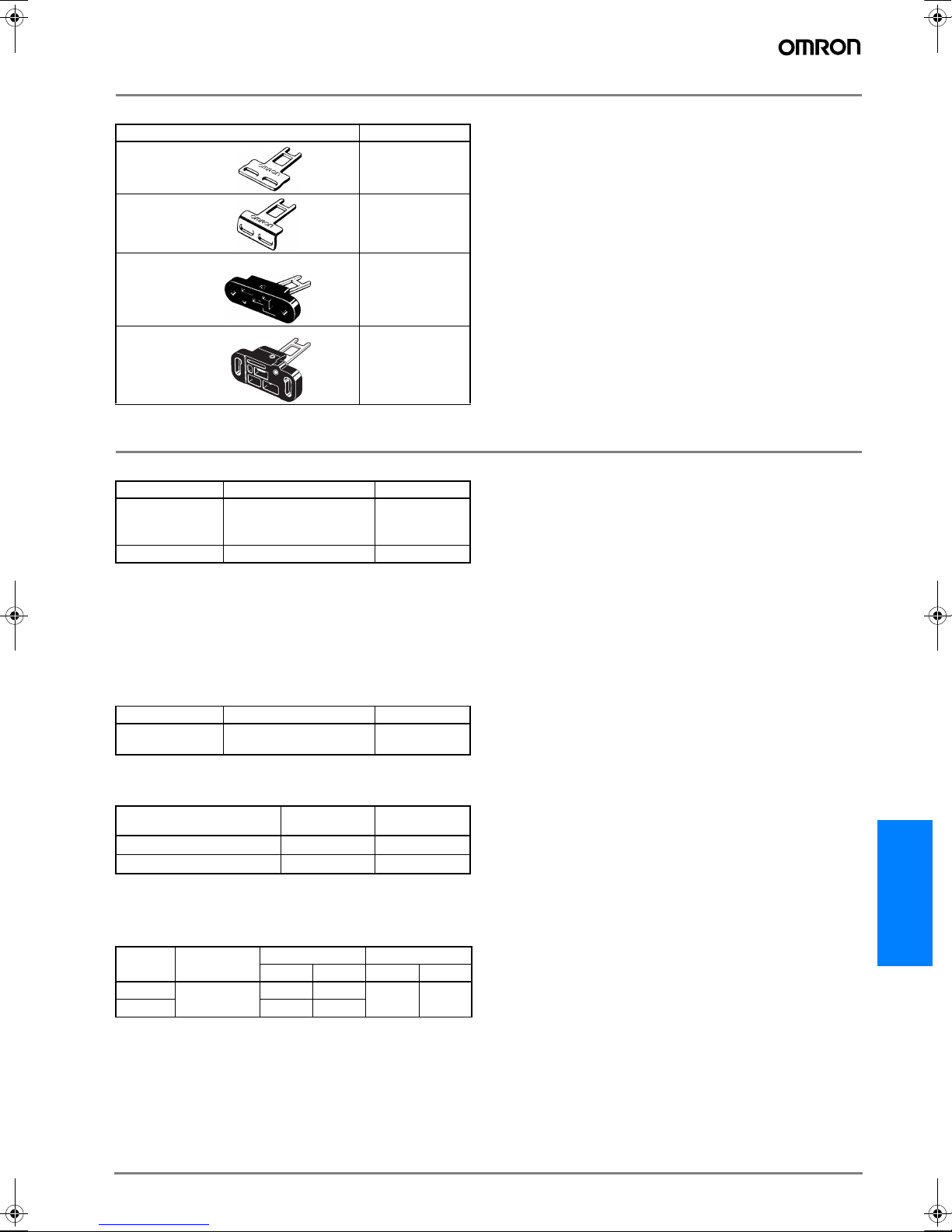
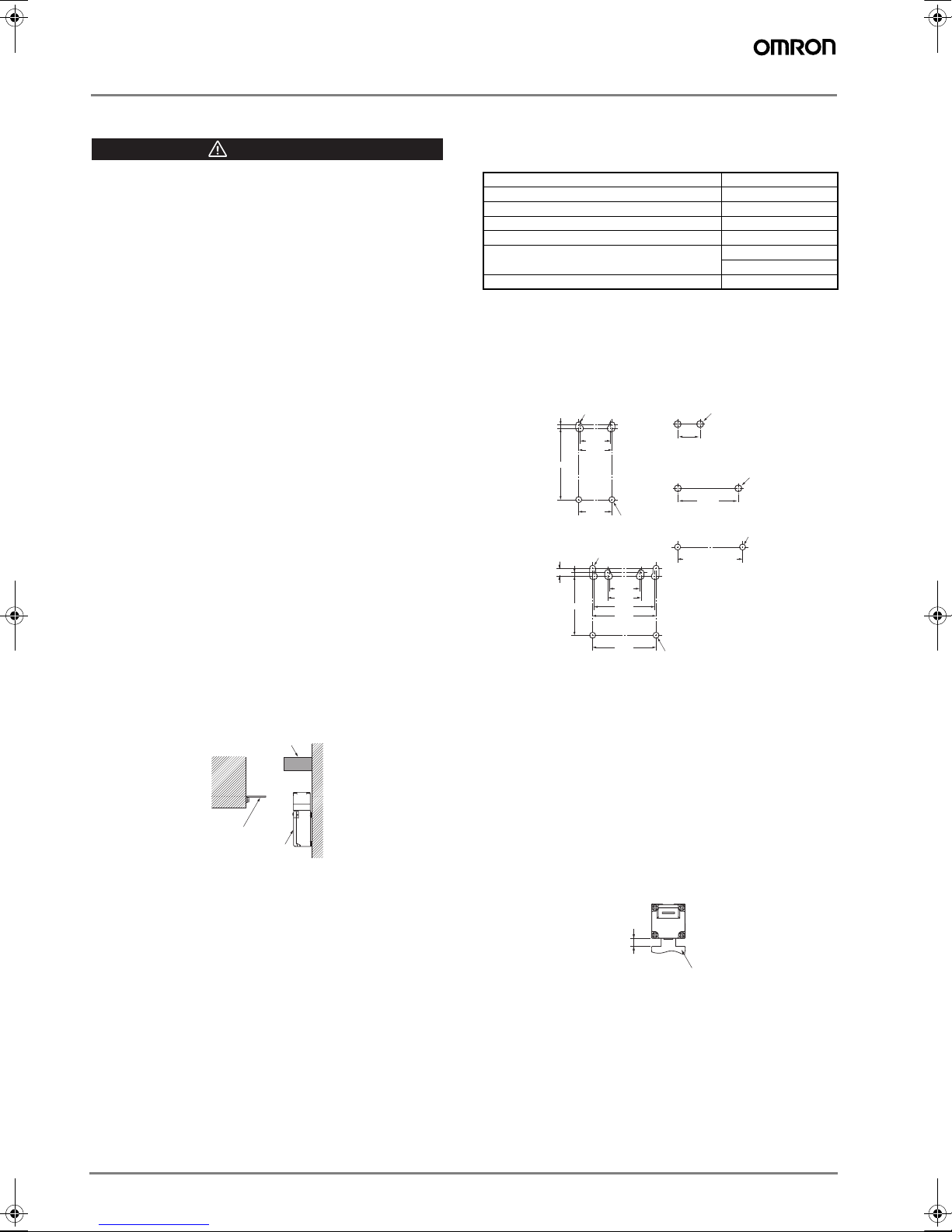
•Do not use the switch as a stopper.
Be sure to install a stopper as shown in the following illustration to
prevent the edge of the operation key from inadvertently hitting the
switch directly.
Precautions for Correct Use
1. Environment
•The switch is intended for indoor use only.
•Do not use your D4NS outdoor, or the switch will malfunction.
•Do not use your D4NS in the atmosphere of hazardous gases
(H2S, SO2, NH3, HNO3, CI2, etc.) or high temperature and
humidity, or it will cause the imperfect closing of the contacts or the
breakage thereof stemming from corrosion.
•Do not use the switch under any of the conditions mentioned
below.
•Frequent temperature range.
•High humidity or dew condensation may be generated.
•Where the switch is subject to severe vibration.
•Where the metal dust, oil, or chemical is sprayed inside the
door.
•Where thinner is applied.
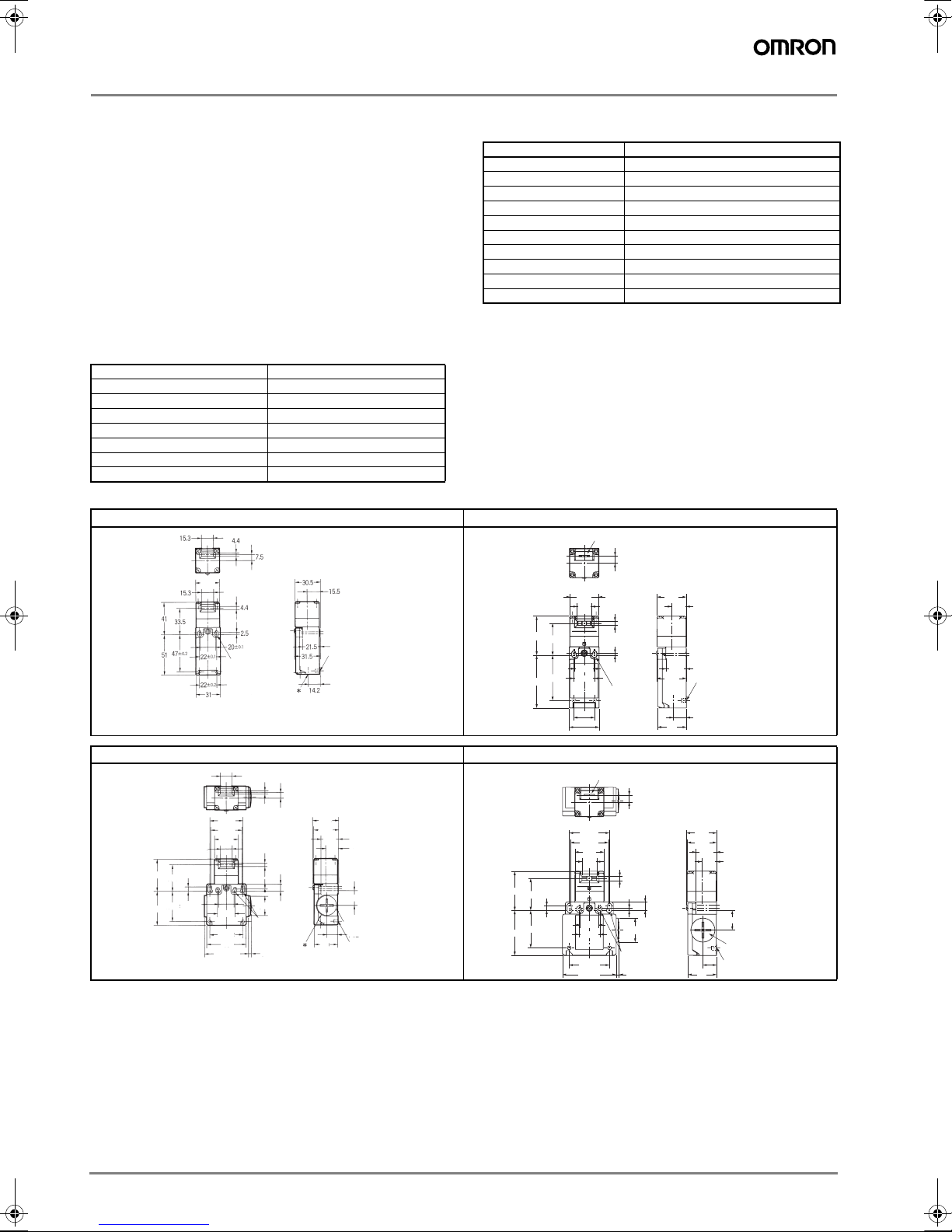
2. Mounting method
•Mounting Screw Tightening Torque
Loose mounting may result in malfunction.
Fasten the screws to the specified torque.
•Switch, operation key
•The switch and operation key will be fastened to specified
torque in item 2 with M4 screws and washers.
•Secured more by the studs like below picture 4-0.05/-0.15 dia.,
4.8 max. height at the lower two which are inserted from back
side of switch.
•Do not use the operation key other than dedicated OMRON's.
Otherwise switch may be damaged.
•Be sure that the operation key can be inserted properly to key
hole with a tolerance of ± 1 mm.
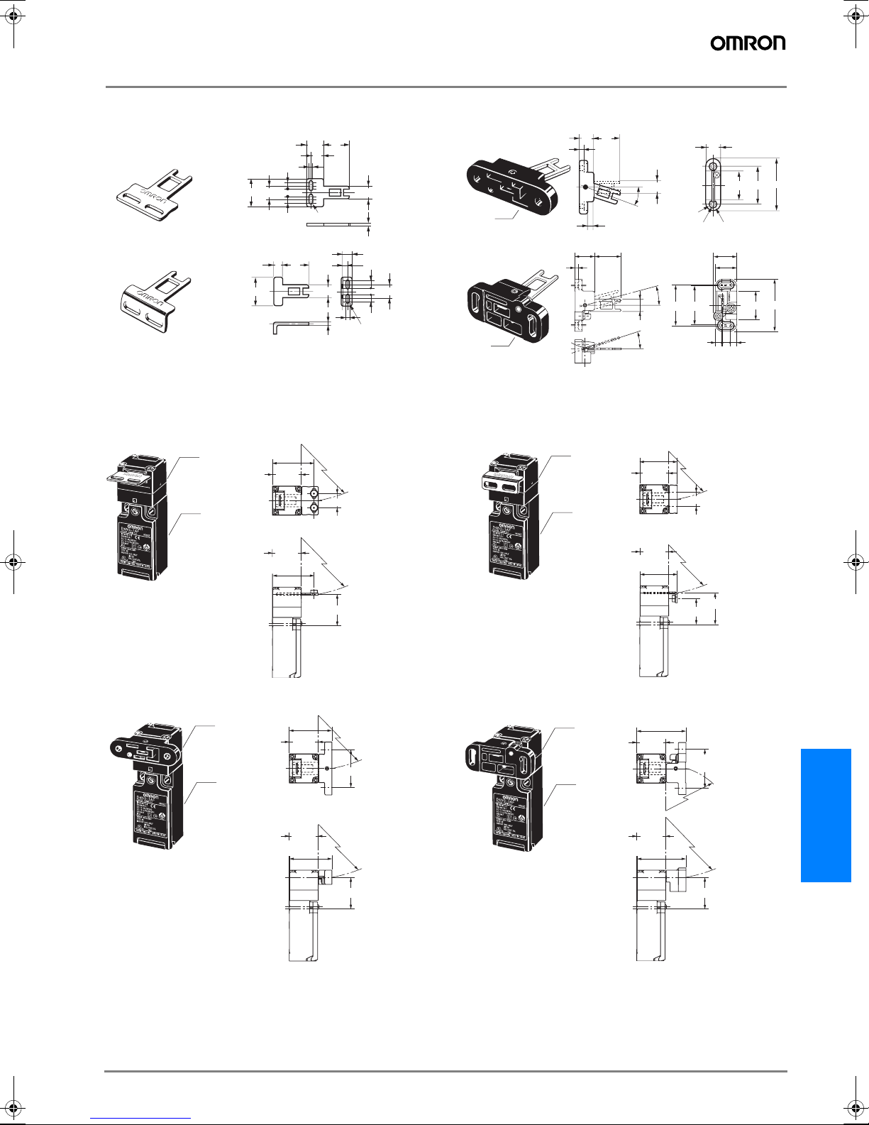
3. Head direction
The rotation of the switch head may be adjusted to any of the four
directions by loosening the head clamping screws at the four
corners of the head.
4. Securing of the door
If the operation key is pulled in the opening direction due to a
force caused by vibration, by the door weight, or by a cushion
attached to the door.
The closed door must be secured with a hook or by similar
means.
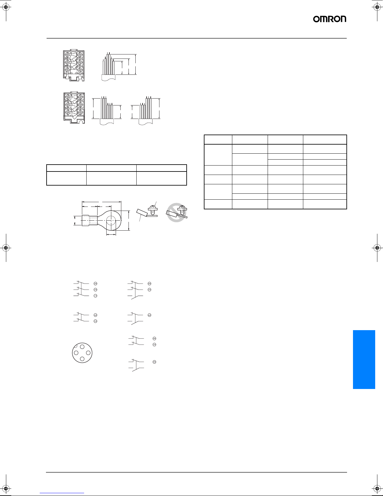
5. Wiring
•When connect with insulation tubes and terminals, connect the
terminals as shown in the following figure and wire without
overriding to the case and the cover. Adequate conductor size is
AWG 20 to 18 (0.5 to 0.75 mm2).
Wire leads as shown in the following figure. Otherwise, the
switch cover does not fit.
CAUTION
Switch
Operation Key
Stopper
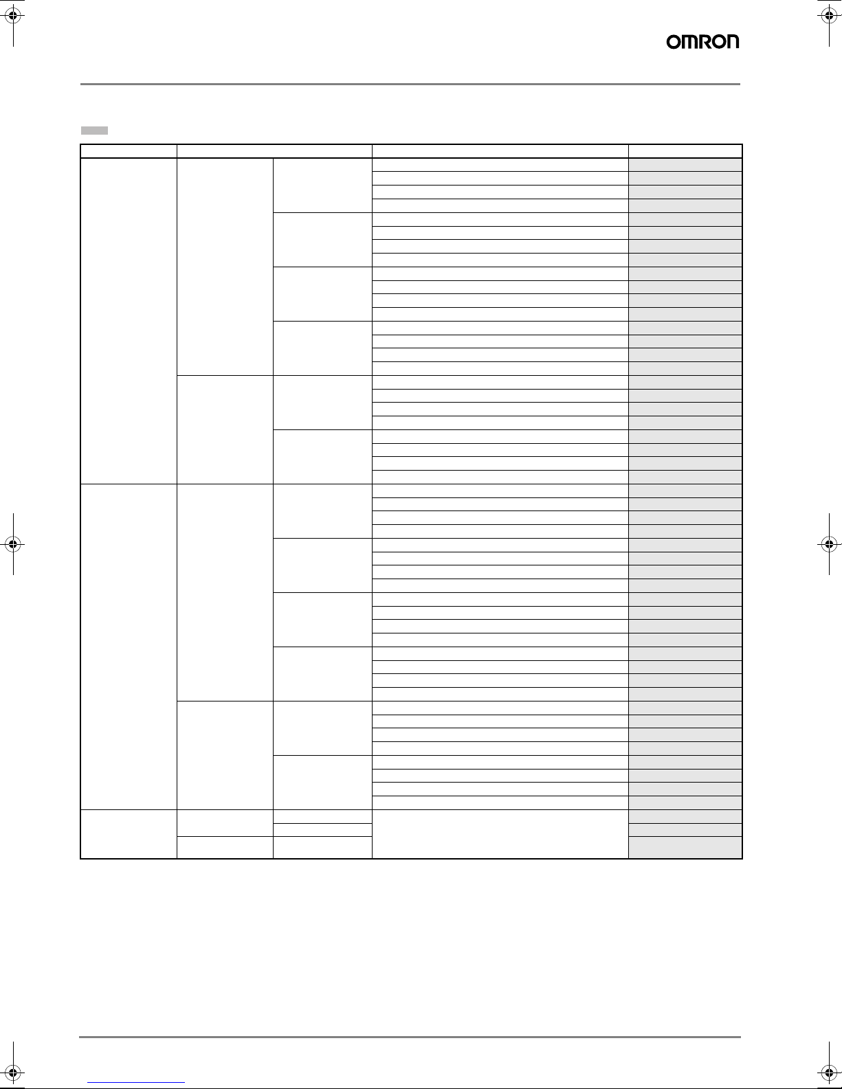
Terminal screw 0.6 to 0.8 N·m
Cover clamping screw 0.5 to 0.7 N·m
Head clamping screw 0.5 to 0.6 N·m
Operation Key clamping screw (See item 4) 2.4 to 2.8 N·m
Body clamping screw (See item 4) 0.5 to 0.7 N·m
Conduit mounting connection (see item 10,11),
M12 changing adaptor 1.8 to 2.2 N·m
1.4 to 1.8 N·m (1/2-14NPT)
Cap screw 1.3 to 1.7 N·m
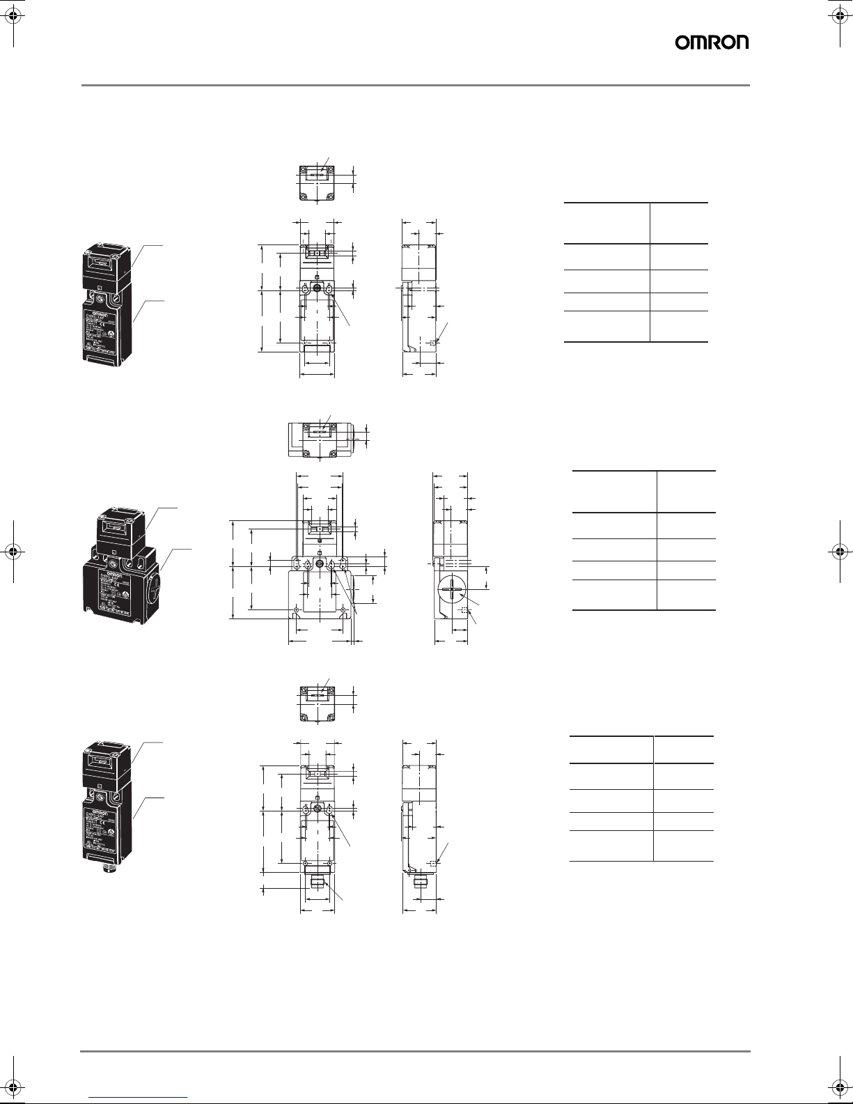
(Switch mounting holes)
(1 conduit type)
(2 conduits type)
(Operation key mounting hole)
D4DS-K3
D4DS-K5
40
±0.1
Two, M4
15
±0.1
Two, M4
41
±
0.1 or, 43
±
0.1
Two, M4
22
±
0.1
47
±
0.1
20
±
0.1
22
±
0.1
2.5
Two, M4
−0.15
4−0.05 dia. height,
4.8 max.
42
±
0.1
39
±
0.1
20
±
0.1
22
±
0.1
40
±
0.1
42
±
0.1
2.5
±
0.1
5.35
±
0.1
Two, M4
−0.15
4−0.05 dia. height,
4.8 max.
D4DS-K1/-K2
Operation Key
Set zone
(0.5 to 3 mm)
F502-EN2-04.book Seite 138 Dienstag, 26. Juli 2005 5:48 17