Omron D4BL - User manual

D4BL
2
Locking Safety-Door Switch
Protective Doors Are Locked Until
Machines Completely Stop Operating
HThe switch contact is opened by a positive
opening mechanism (NC contacts only).
Positive opening mechanism that is
EN-approved is indicated by on the
switch
HAuxiliary release key ensures easy
maintenance and unlocks the door in the
case of a power failure
HTough aluminum die-cast Unit incorporating
a switch box with IP67 degree of protection
(EN60529, IEC529)
HStandards and EC Directives:
Conforms to the following EC Directives:
Machinery Directive
Low Voltage Directive
EN1088
HApproved Standards
Agency Standard File No.
TÜV Rheinland EN60947-5-1 R9451050
(Positive opening:
approved)
UL UL508 E76675
CSA CSA C22.2, No.14 LR45746
BIA GS-ET-19 Mechanical lock:
9402293
Solenoid lock:
1998 20462-01
SUVA SUVA E6186/1.d
EuC

D4BL
3
Ordering Information
JMODEL NUMBER LEGEND
D4BL --
12
1. Conduit
1: PG13.5 (European type)
2: G1/2 (Japanese type)
3: 1/2-14NPT (North American type)
2. Built-in Switch
C: 1NC/1NO (Slow-action) + 1NC (Slow-action)
D: 2NC (Slow-action) + 1NC (Slow-action)
3. Head Mounting Direction
R: Mounting possible in 4 directions
(mounted in the right direction at time of delivery)
34
D4BL - K
1
Switch
Operation Key (Order Separately)
5
1. Operation Key Type
1: Horizontal mounting
2: Vertical mounting
3: Adjustable mounting (Horizontal)
4. Door Lock/Release Methods
(Auxiliary Release Key is Incorporated by All Models)
5. Indicator
A: Mechanical lock/24-VDC solenoid release
B: Mechanical lock/110-VAC solenoid release
G: 24-VDC Solenoid lock/Mechanical release
Blank: Without indicator
A: 1mAat10to115VACorVDCdriving
(with red and green LED indicator unit)
JSWITCHES
Description Part number
Lock
method Conduit size/type Voltage
for
solenoid
Without indicator
1NC/1NO+ 1NC
(Slow-action)
With LED indicator
1NC/1NO+ 1NC
(Slow-action)
Without indicator
2NC+ 1NC
(Slow-action)
With LED indicator
2NC+ 1NC
(Slow-action)
Mechanical
l
k
PG13.5 (European) 24 VDC D4BL-1CRA D4BL-1CRA-A D4BL-1DRA D4BL-1DRA-A
lock 110 VAC D4BL-1CRB D4BL-1CRB-A D4BL-1DRB D4BL-1DRB-A
G1/2 (Japanese) 24 VDC D4BL-2CRA D4BL-2CRA-A D4BL-2DRA D4BL-2DRA-A
110 VAC D4BL-2CRB D4BL-2CRB-A D4BL-2DRB D4BL-2DRB-A
1/2-14NPT
(
N
t
h
A
i
)
24 VDC D4BL-3CRA D4BL-3CRA-A D4BL-3DRA D4BL-3DRA-A
/
(North American) 110 VAC D4BL-3CRB D4BL-3CRB-A D4BL-3DRB D4BL-3DRB-A
Solenoid
l
k
Pg 13.5 (European) 24 VDC D4BL-1CRG D4BL-1CRG-A D4BL-1DRG D4BL-1DRG-A
lock G1/2 (Japanese) 24 VDC D4BL-2CRG D4BL-2CRG-A D4BL-2DRG D4BL-2DRG-A
21/2-14NPT
(North American) 24 VDC D4BL-3CRG D4BL-3CRG-A D4BL-3DRG D4BL-3DRG-A

D4BL
4
JOPERATION KEY (ORDER SEPARATELY)
Mounting type Part number
Horizontal mounting D4BL-K1
Vertical mounting D4BL-K2
Adjustable mounting
(Horizontal) D4BL-K3
Specifications
JAPPROVED STANDARD RATINGS
TÜV (EN60947-5-1)
Item Standard model Indicator model
Utilization category AC-15 AC-15
Rated operating current (Ie) 3A 6A
Rated operating voltage (Ue) 250 V 115 V
As protection against short-circuiting, use either a gI-type or gG-type 10-A fuse (IEC269-approved).
UL/CSA (UL508, CSA C22.2 No. 14)
A300
Rated voltage Carry current Current Volt-amperes
y
Make Break Make Break
120 VAC 10 A 60 A 6A 7,200 VA 720 VA
240 VAC 30 A 3A
Note: The UL/CSA approved rating for products with indicators (-A) is 6 A/115 VAC.

D4BL
5
JCHARACTERISTICS
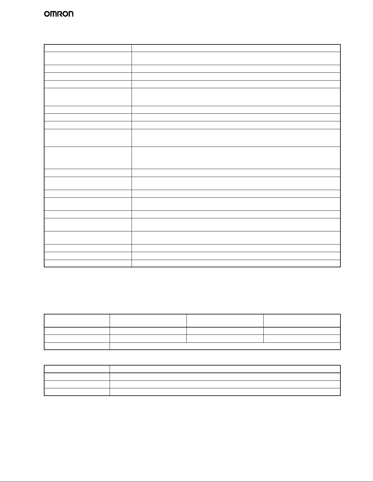
Degree of protection IP67 (See note 2.)
Life expectancy (See note 3.) Mechanical: 1,000,000 operations min.
Electrical: 500,000 operations min.
Operating speed 0.05 to 0.5 m/s
Operating frequency 30 operations/min max.
Rated frequency 50/60 Hz
Operating characteristics Positive opening force: 19.61 N min. (EN60947-5-1)
Positive opening stroke: 20 mm min. (EN60947-5-1)
All stroke:23 mm min.
Locked resistive pulling force 700 N min. (GS-ET-19)
Insulation resistance 100 MΩmin. (at 500 VDC)
Rated insulation voltage (Ui)300 VAC (EN60947-5-1)
Conventional enclosed thermal
current (Ithe) (rated continuous
current)
10 A (EN60947-5-1)
Dielectric strength (Uimp)Impulse dielectric strength (Uimp) 4 kV (EN60947-5-1) between terminals of different polarity,
between each terminal and ground, and between each terminal and non-current-carrying metal
part;
2.5 kV between solenoid and ground
Conditional short-circuit current 100 A (EN60947-5-1)
Operating environmental pollution
level Pollution degree 3 (EN60947-5-1)
Electric shock protection class Class I (with grounded terminal)
Counter electromotive voltage at
switching 1,500 V max. (EN60947-5-1)
Contact resistance 50 mΩmax. (initial value)
Vibration resistance Malfunction: 10 to 55 Hz, 0.35-mm single amplitude with an imposed acceleration of 50 m/s2
max. (IEC68-2-6)
Shock resistance Destruction: 1,000 m/s2min. (IEC68-2-27)
Malfunction: 300 m/s2min. (IEC68-2-27)
Ambient temperature Operating: --10°Cto55°C (with no icing)
Ambient humidity Operating: 95% max.
Weight Approx. 800 g
Note: 1. The values provided in the above table are the initial values.
2. Although the switch box does not allow the penetration of dust, oil or water, avoid as much as possible the penetration of dust,
oil, or water into the head’s Operation Key insertion slot.
3. The life expectancy is for an ambient temperature of 5°Cto35°C and ambient humidity of 40% to 70%. For further conditions,
consult your OMRON sales representative.
Solenoid Coil Characteristics
Item 24-VDC Mechanical lock models 110-VAC Mechanical lock
models 24-VAC Solenoid lock models
Rated operating voltage 24 VDC +10%/--15% (100% ED) 110 VAC ±10% (50/60 Hz) 24 VDC +10%/--15% (100% ED)
Current consumption Approx. 300 mA Approx. 98 mA Approx. 300 mA
Insulation class Class F (130°Corless)
Indicator Characteristics
Item LED
Rated voltage 10 to 115 VAC/VDC
Current consumption Approx. 1 mA
Indicator color (LED) Orange, green

D4BL
6
Nomenclature
D4BL-jCjj-jD4BL-jDjj-j
Operation Key
Lock plate
Rotating drum
Operation plunger
Seal ring (NBR)
Auxiliary plunger
Seal packing (NBR)
Rotating lever
Safety switch
Seal packing (NBR)
Conduit opening
(vertical wiring)
Ground terminal M3.5
Connection
terminal M3.5
Conduit opening
(horizontal wiring)
Solenoid
Lock monitor switch
Auxiliary release key
Operation
JCONTACT FORM (DIAGRAMS SHOW STATE WITH KEY INSERTED AND LOCK ENGAGED)
Model Contact Diagrams Remarks
D4BL-jCjj-j1NC/1NO+1NC
31 32 11 12
24
23
31 -- 12
23 -- 24
Stroke
ON
Lock position
Operation Key
insertion comple-
tion position
Pull-out
completion
position
Only NC contacts
11-12 and 31-32
have an approved
positive opening
mechanism.
Terminals 11-12
and 23-24 can be
used as unlike
poles.
D4BL-jDjj-j2NC+1NC
12
22
113231
21
31 -- 12
21 -- 22
Stroke
ON
Lock position
Operation Key
insertion comple-
tion position
Pull-out
completion
position
NC contacts 11-12,
21-22, and 31-32 all
have an approved
positive opening
mechanism.
Terminals 11-12
and 21-22 can be
used as unlike
poles.
Note: The EN-approved positive opening mechanism is indicated by on the switch.

D4BL
7
JINDICATOR UNIT
Dimensions
16
16
7
35 26.2
61.2
0.3
5.6
26.8 53.2 57.2
210.6
12.6
Two, 7 dia.
Four terminal plates
Two indicators
Internal Circuit
LED
R
ZD
R
10 to 115 VAC/DC
Constant-current diode
Recommended Circuit Connection Example
1. Connect the crimp-style terminals of each indicator unit to
the internal terminals (terminals 31 and 12, 23 and 24, and
21 and 22) of the D4BL.
2. Each indicator unit must be connected in parallel with the
contacts. When the contacts are open, the indicators will
be lit.
E1 E2 31 12 23 24
E1 E2 23 24
12113231
Orange Green
Power supply
+--
Load
Load

D4BL
8
JOPERATING MODE
(Example of Electromagnetic Interlock System Operating Mode of D4BL-jCjA-A)
Operating
mode III III IV
Door Theprotectivedooris
open. The protective door is
closed. Theprotectivedooris
closed and the machine is
operating.
Theprotectivedooris
closed and the solenoid is
operating.
Door
switch Operation Key: The
mechanical lock is
released (contacts 31
and32areOFF).
Main Switch: The
normally closed contact
is forcibly opened
(contacts 11 and 12 are
OFF).
E1 E2 31 12 23 24
E1 E2 23 24
12113231
Operation Key (door)
Orange Green
+--
Operation Key:
Mechanically locked
(contacts 31 and 32 are
ON).
Main Switch: The
normally closed contact
is closed (contacts 11
and12areON).
E1 E2 31 12 23 24
E1 E2 23 24
12113231
Operation Key (door)
Orange Green
+--
The protective door is closed
and the machine is operating.
E1 E2 31 12 23 24
E1 E2 23 24
12113231
Operation Key (door)
Orange Green
+--
Operation Key: The
mechanical lock is
released (contacts 31
and32areOFF).
E1 E2 31 12 23 24
E1 E2 23 24
12113231
Operation Key (door)
Orange Green
+--
Contact 31 and 12 23 and 24 31 and 12 23 and 24 31 and 12 23 and 24 31 and 12 23 and 24
OFF ON ON OFF ON OFF OFF OFF
Control
device
(2)
Safety
work
indication
(3)
Confirmation
of door
closing
(5)
Machine
interrupt
signal
(6)
Confirmation
of machine
interruption
(8)
Release
confirmation
signal
(7)
Lock
release
signal
(4)
Start
signal
(1)
Confirmation
of door
opening
Machine (Processing)
(Interruption)
(Start)
(Interruption) (See note)
(Completion)
Indicator Orange: ON
Green: OFF Orange: OFF
Green: ON Orange: OFF
Green: ON Orange: ON
Green: ON
Note: 1. Be sure to use the dedicated push button to start or stop the machine or release the door lock.
2. Solenoid terminals E1and E2 of 24-VDC solenoid release models have the following polarities. Confirm the polarities before
wiring.
E1: +
E2: --
3. Solenoid terminals E1 and E2 of 110-VAC solenoid release models have no polarity.

D4BL
9
Dimensions
Unit: mm (inch)
Note: A tolerance of ±0.4 mm applies to all dimensions unless otherwise specified.
JSWITCHES
D4BL-jjjj-j
116.5
34.2
123.5
6.8
31.5
17
7
46.3
39.6
16
37.5
10
5.5
Four, M3.5 head
clamping screws
Conduit opening
Indicators
Conduit opening
Lock
protection
cap
Four, 5.3 dia.
mounting
holes
Four, M4
cover
clamping
screws
100±0.1
74±0.1
Cover
112 +1
0
86 +1
0
15
Red
JOPERATION KEYS
40
26
40
2012
80.7
36
5.6
11.8
30
34.6
17.5
2.6
37.8
19.5±0.1
4dia.
5.3 dia.
30±0.15
M4 Allen-head bolt
15.6
53.7 13
25.8
11.8
5.6
2.6
36 5.3 11.9 7.5
20
40±0.15
5.3 x 7.3 mounting long hole
4dia.
52.4
Horizontal Mounting
D4BL-K1
V
ertical Mounting
D4BL-K2
Adjustable Mounting (Horizontal)
D4BL-K3
25.8 15.6
40.7
78.7
36
7.3 15
5.3 5.3
20
7.5
2.6
5.6
11.8
4dia.
Two, R2.65
20±0.15
Red
Red
Red
Red

D4BL
10
JWITH OPERATION KEY INSERTED
Adjustable Mounting (Horizontal)
D4BL + D4BL-K3
Horizontal direction
Operation Key insertion radius
R≧250 (side view)
30±0.15
81.5 min. 85 max.
Horizontal Mounting
D4BL + D4BL-K1
Vertical Mounting
D4BL + D4BL-K2
41 40
Vertical direction
Operation Key insertion radius
R≧1000 (side view)
35
81.5 min. 85 max.
41
41 13
40±0.15
54.5 min. 58 max.
Horizontal direction
Operation Key insertion radius
R≧1200 (side view) 54.5 min. 58 max.
Vertical direction
Operation Key insertion radius
R≧1000 (side view)
41
35
20±0.15
Horizontal direction
Operation Key insertion radius
R≧1200 (side view)
Vertical direction
Operation Key insertion radius
R≧1000 (side view)
20±0.15
35
41
41
53.5 min. 57 max.
12
53.5 min. 57 max.
Red
Red
Red

D4BL
11
Installation
JCONNECTION EXAMPLE WITH OMRON’S G9S SAFETY RELAY UNIT
IN
PC Motor control
system
OUT C12C12
G9S-301 (24 VDC)+D4BL-jCRG-j(Solenoid lock type)+D4D-j520 N
23
31
32
12
11 23
24
11
12 24
E-SW
T11 T12 T22 T21
G9S
Circuit Diagram
PC output
PC output (Stop signal) Feed back loop
(Operation instruction)
Emergency stop or standby
Closed
Open
S2
S1
KM1 KM2
S1: D4DN or D4BN Safety-door Lock Switch
S2: D4BL Guard Lock Safety-door Lock Switch with solenoid lock
S3: Reset switch
KM1, KM2: J7K Magnet Contactor
M: 3-phase motor
E-SW: Emergency stop switch (A22E)
R1
Note: Wire terminal 11 and terminal 22
on G9S to the PC output common.

D4BL
12
JCONNECTION EXAMPLE WITH OMRON G9S SAFETY RELAY UNIT
G9S-321-Tj(24 VDC)+D4BL-jCRA-j/-jCRB-j(Mechanical lock type)+D4D-j520N
23
31
32
12
11 23
24
11
12 24
E-SW
T11 T12 T22 T21
G9S
IN
PC
S1: Safety Switch (D4D-j520N)
S2: D4BL Guard Lock Safety-door Lock Switch with mechanical lock
S3: Push-button switch for solenoid
KM1, KM2: Magnet Contactor (LC1-D)
M: 3-phase motor
E-SW: Emergency-stop switch (A22E)
Circuit Diagram
PC output
PC output (Stop signal)
Feed back loop
(Operation instruction)
Emergency stop or
standby
Motor control
system
KM1
KM2
S2
Closed
Open
S1
Off delay
timer
OUT C1 2C1 2
S3
Note: Wire terminal 11 and terminal 22
on G9S to the PC output common.

D4BL
13
Precautions
!CAUTION
Do not insert the Operation Key into the key hole while the
protective door is open. Before using the machine, be sure to
remove the shock-absorbing damper, which is provided before
shipping. Otherwise the machine will operate, and injury may
result.
JNOTICE
Be sure to mount the Operation Key so that it will not come into
contact with the human body, or injury may result.
If the D4BL is applied to an emergency stop circuit or safety
circuit for prevention of injury, use the NC contact, which has a
force-separation mechanism, and make sure that the D4BL
operates in the positive mode. Furthermore, secure the D4BL
with screws or equivalent parts that are tightened in a single
direction so that the D4BL or Operation Key cannot be easily
removed, or install a protection cover for the D4BL and post a
warning label near the D4BL.
In order to protect the D4BL from damage due to short-circuiting,
connect a fuse breaking a current 1.5 to 2 times higher than the
rated current in parallel with the D4BL.
If an application satisfying EN standardsistoemploytheD4BL,
apply a 10-A gI or gG fuse approved by IEC269.
In order to prevent the D4BL from burning due to overvoltage,
insertaprotectionfuseinto the solenoid circuit.
If the D4BL is imposed with force exceeding the lock strength,
the D4BL may break and the equipment may continue to operate.
Auxiliary Release Key
The auxiliary release key is used to unlock the D4BL in case of
emergency cases or in case the power supply to the D4BL fails.
Use an appropriate tool to set the auxiliary release key to
UNLOCK so that the lock will be released and the door can be
opened.
Auxiliary
release key
UNLOCK
LOCK
The auxiliary release key applied to the door of a machine room
ensures the safety of people adjusting the equipment in the
machine room. If the auxiliary release key is set to UNLOCK, the
door will not be locked when the door is closed and no power will
be supplied to the equipment.
To lock the door, set the auxiliary release key to LOCK.
Do not use the auxiliary release key to start or stop machines.
To prevent the auxiliary release key from being handled
carelessly by unauthorized people, seal the auxiliary release key
with sealing wax and the provided seal cap to ensure IP67.
Make sure that the auxiliary release key is kept with the person in
charge.
Before attaching the cover to the D4BL, make sure that the
auxiliary release key position is set to LOCK.
Mount with a Stopper
Stopper
Switch
Do not apply the D4BL to
the door of a machine
room without applying a
stopper to the door. If ex-
cessive force is imposed
on the D4BL, the lock
mechanism may break
and the equipment in the
machine room may start
to operate.
JCORRECT USE
Operating Environment
Due to the wear and tear of the sealing of the D4BL, water and
some types of oil and chemical sprayed onto the D4BL may
cause contact or insulation failures, current leakages, or fires.
Do Not Use the D4BL in the Following Places
•Places with radical temperature changes.
•Places with excessive humidity that may cause condensa-
tion.
•Places with excessive vibration.
•Places where metal dust, oil, or chemical may be sprayed
onto the D4BL.

D4BL
14
Operation Key
The D4BL is provided with a shock-absorbing damper to protect
the D4BL from damage that may result from dropping the D4BL
during transportation. Be sure to remove the damper after
mounting the D4BL.
The mounting tolerance of the Operation Key is ±0.3 mm vertically
or horizontally. Be sure to mount the D4BL correctly without leaning,
or the D4BL may soon break or wear out.
±0.3 min.
±0.3 min.
Do not drop the D4BL with the Operation Key inserted, otherwise
the Operation Key may deform or break.
Drop
The head is constructed so that it cannot be operated with
tools such as screwdrivers. Always use OMRON’s Operation
Key to operate the head in order to ensure the safety of the
machine and protect the D4BL from damage.
The Operation Key provided for the D4BL is not compatible
with that of the D4BS.
Mount the Operation Key and only secure it with screws that
will tighten when turned clockwise or counterclockwise.
Set zone
Space
Door Security
The D4BL may break soon if the door opens accidentally or
a space is present between the set zone of the Key and the
D4BL as shown below. This may be due to the weight of the
door, vibration of the machine, or bouncing of the door
against the rubber bumper. Be sure to apply appropriate
parts, such as hooks, so that no such space will exist.
JMOUNTING
Tightening Torque
Be sure to tighten each screw of the D4BL properly, or the D4BL
may malfunction.
Type Proper tightening torque
1Terminal screws and M3
ground terminal screws 0.59 to 0.78 N Sm
2Cover-mounting screws 1.18 to 1.37 N Sm
3Head-mounting screws 0.78 to 0.98 N Sm
4Switch-mounting screws
(M5) 4.90 to 5.88 N Sm
5Operation Key mounting
screws 2.35 to 2.75 N Sm
6Connectors 1.77 to 2.16 N Sm
7Cap screws 1.27 to 1.67 N Sm
Two, M5 Operation Key mounting screw
Four, M3.5 head-mounting screw
Four, M4 cover-mounting screw
Conduit Four, M5
switch-mounting
screw
Conduit cap

D4BL
15
Switch and Operation Key Mounting
Mount the D4BL and Operation Key with four M5 screws with
washers and tighten each screw to the specified torque.
Mounting Dimensions
Switch Mounting Dimensions
Four, M5
100±0.1
74±0.1
Operation Key Mounting Holes
Horizontal Mounting
D4BL-K1
20±0.1
Two, M5
Vertical Mounting
D4BL-K2
40±0.1
Two, M5
Adjustable Mounting (Horizontal)
D4BL-K3
30±0.1
Two, M5
Head Directions
Theheadcanbemountedinfourdirections. To remove the head,
turntheheadby45°as shown in figures A and B below.
To change the direction of the head, make sure that the
protruding part of the rotating lever engages with the groove of
the plunger. Then turn the head clockwise or counterclockwise to
the desired direction. At that time, make sure that the groove of
the plunger is located under the rotating lever. If the direction of
the head is not set when the plunger is rotated by 45°, the groove
of the plunger presses the rotating lever. The head, plunger, or
thebuilt-inswitchmaybedamagedasaresult.
Head Direction Changes
Left
Front
(A) (B) Back
Right
(45°)
(45°)
Operation plunger and
groove mechanism Rotation lever and
protruding part
Head Bottom View Switch Top View

D4BL
16
Switch body
Rotating lever (with
protruding part)
Plunger (with groove)
Built-in switch
Normal Positions of Rotating Lever
and Plunger
Be sure to check the mechanical lock and solenoid release
functions when mounting the D4BL.
If the head direction is changed, recheck the tightening torque of
each of screw. Make sure that no foreign materials will penetrate
throughthekeyholeonthehead.
Mounting the Cover
When tightening the cover, first check the specified torque, and
then tighten each screw to the that torque. Also, make sure that
no foreign matter has entered the switch.
When mounting the cover, make sure that the cover and switch
box are properly aligned.
JPROCESSING AND CONNECTING
CABLE/CONDUIT
The following procedures are recommended for mounting and
wiring the indicator unit securely.
In order to ensure IP67, use OMRON’s SC-jM and Nippon
Flex’s ABS-08Pg13.5 and ABS-12 Pg13.5 Connectors.
Recommended cable: UL2464-type cable that is 20 to 18 AWG
(0.5 to 1.0 mm2) in size and has seven conductors
If the 1/2-14NPT is used, cover the cable and conduit end with
sealingtapeinordertoensureIP67. Tighten the connector to a
torque of 1.77 to 2.16 N Sm.
Connect the indicator unit after connecting the seven-conductor
cable.
Terminal no. Lp (mm) Lv (mm) a (mm)
E130±280±28±1
E235±275±2
31 45±260±2
12 55±250±2
23 (21) 65±245±2
24 (22) 70±235±2
90±250±2
Properly attach and securely tighten the provided conduit cap to the
unused conduit opening when wiring the D4BL.

D4BL
17
Cable Connection Example
1. Connect the wires to the terminals in the order shown below
for wiring efficiency.
Tighten each wired terminal clockwise to a torque of 0.59 to
0.78 N Sm.
Twist the wire two or three times and make sure that no bare
wire exists outside the terminal when tightening the terminal.
2. The insulation sheath of the seven-conductor cable must
come into contact with the wall of the conduit mouth, side A
or side B.
Insulation sheath edge
Maintenance and Repairs
Contact your OMRON representative for any repair or
maintenance work on the D4BL. The D4BL must not be
maintained or repaired by any unauthorized party.
Using the D4BL
Do not touch the solenoid because the solenoid radiates heat
while power is being supplied.
OMRON ON-LINE
Global - http://www.omron.com
USA - http://www.omron.com/oei
Canada - http://www.omron.ca
ALL DIMENSIONS SHOWN ARE IN MILLIMETERS. To convert millimeters into inches, divide by 25.4
Cat. No. GC SAFETY-2 Printed in USA
OMRON CANADA, INC.
885 Milner Avenue
Toronto, Ontario M1B 5V8
416-286-6465
OMRON ELECTRONICS LLC
One Commerce Drive
Schaumburg, IL 60173
847-843-7900
For US technical support or other inquiries:
800-556-6766
2/03 Specifications subject to change without notice
Other manuals for D4BL -
6
Table of contents
Other Omron Switch manuals

Omron
Omron F3S-TGR-N C - User manual

Omron
Omron D4BL - User manual

Omron
Omron D4C - User manual

Omron
Omron A165K - User manual

Omron
Omron NL1-C User manual

Omron
Omron A22E - User manual

Omron
Omron D5A - User manual

Omron
Omron D4BL - User manual

Omron
Omron D4SL-N N Series User manual

Omron
Omron WLM - User manual