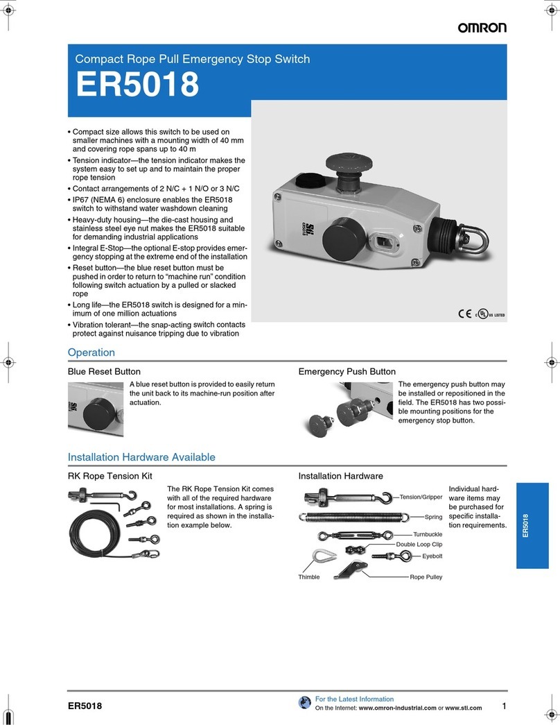
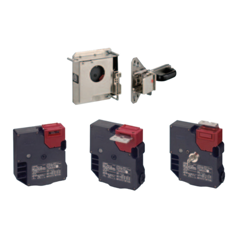
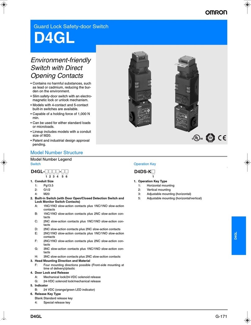
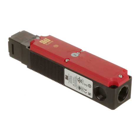
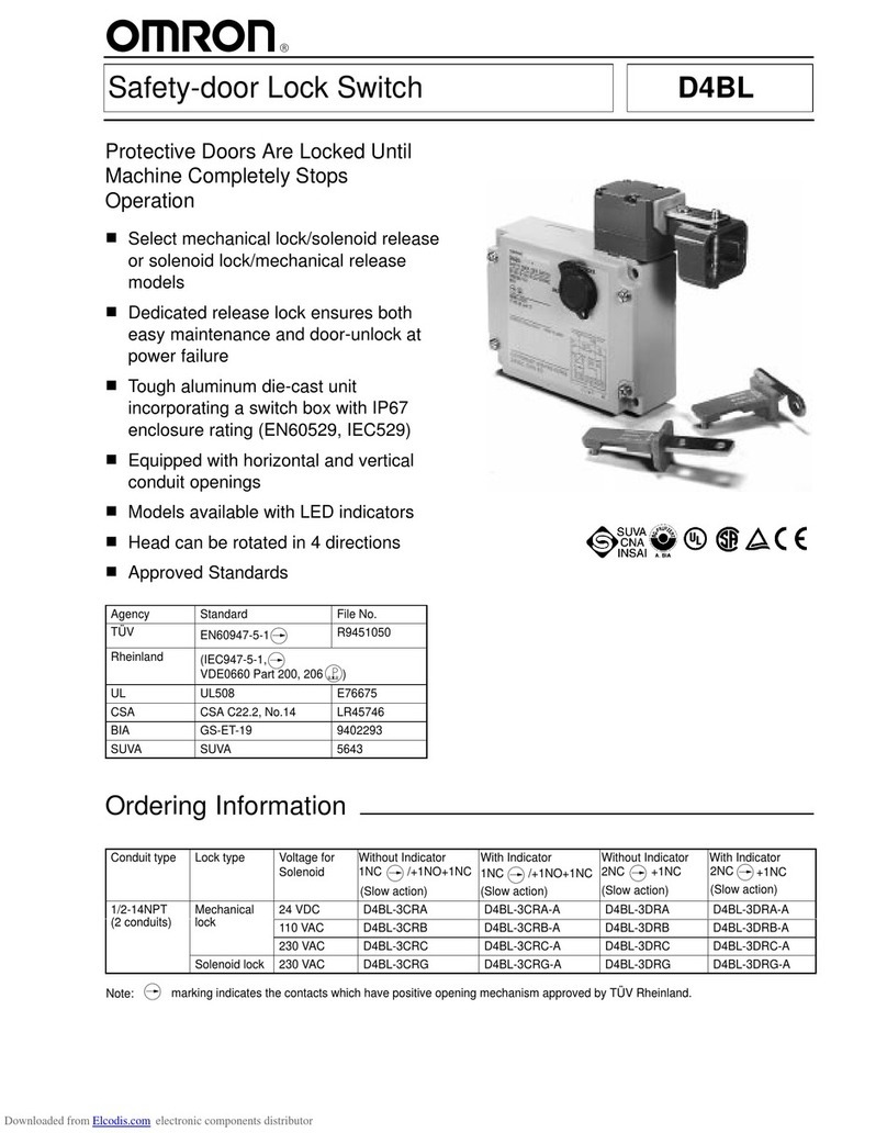
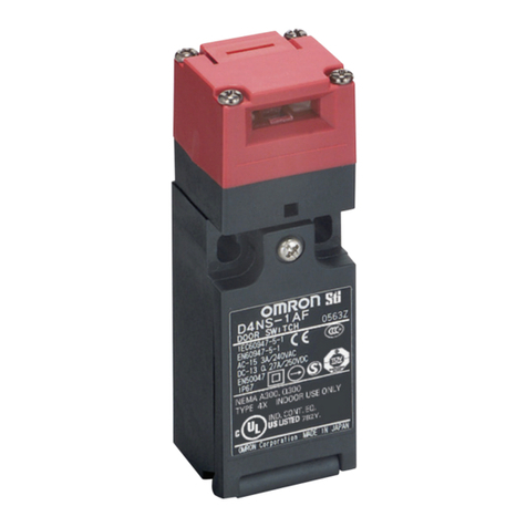
Omron D4JL Series User manual

CSM_D4JL_DS_E_4_1
1
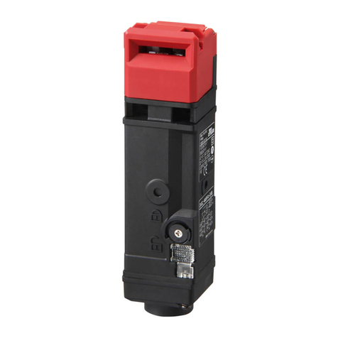
Guard Lock Safety-door Switch
D4JL
World's Top*Holding Force of 3,000 N
*For plastic models, as of May 2008
• Two safety circuits and two monitor contacts provide an
array of monitoring patterns.
• Standard gold-clad contacts enable use with ordinary loads
and microloads.
• Models with trapped keys prevent workers from being locked
in hazardous work areas.
• Models with rear release buttons allow people to unlock the
Switch and escape if they are locked into hazardous areas.
• IP67 degree of protection
Features
Plastic Guard Lock Safety-door Switches
Rank Among the Strongest in the World
A holding force of 3,000 N makes these Switches suitable for large,
heavy doors.
Models with Trapped Keys
(See page 5 for a list of models.)
OMRON also offers Trapped Key Switches (on mechanical lock
models only).
As long as a person has the trapped key when he enters a hazardous
area, he does not have to worry about somebody locking the door and
trapping him inside.
The door can be opened only by supplying power to the solenoid and
then turning the trapped key to unlock the D4JL.
There are thirty different types of trapped keys available for use in
applications with adjacent hazardous areas.
Two Safety Circuits and Two Monitor
Contacts
The D4JL has two safety circuits. It also has two contacts to
separately monitor the open/closed status of the door and the status
of the lock.
Models with Rear Release Buttons
(See page 4 for a list of models.)
A Switch with a rear release button allows the door to be unlocked
from inside a hazardous area in an emergency. OMRON also offers
Switches with Special Slide Keys. Refer to the “D4NS-SK/D4JL-SK”
for details.
Be sure to read the “Safety Precautions” on page 21 and the
“Precautions for All Safety Door Switches”.
41
51 52
63 64
42
Lock Monitor Switch Door Open/Closed
Detection Switch
Monitoring
the door lock
Monitoring the open/
closed status of the door
11 12 To safety circuit
To safety circuit
To control circuit
33 34
2221
Rear release button
Special slide key

D4JL
2
Model Number Structure
Model Number Legend
Switches
1. Conduit Size
1: Pg13.5
2: G1/2
3: 1/2-14NPT *1
4: M20
2. Built-in Switch
N: 2NC/1NO + 2NC/1NO (slow-action contacts)
P: 2NC/1NO + 3NC (slow-action contacts)
Q: 3NC + 2NC/1NO (slow-action contacts)
R: 3NC + 3NC (slow-action contacts)
3. Head Material
F: Plastic
4. Door Lock and Release
A: Mechanical lock/24 VDC solenoid release
G: 24 VDC Solenoid lock/Mechanical release
5. Indicator
C: 24 VDC (green LED indicator)
D: 24 VDC (orange LED indicator)
6. Release Key Type
5: Special release key *2
6: Special release key + rear release button *2
7: Trapped key
7. Trapped Key Type
01 to 30: 30 types *3
Operation Keys
1. Operation Key Type
1: Horizontal mounting
2: Vertical mounting
3: Adjustable mounting (horizontal)
Note: A 24 VDC solenoid lock cannot be combined with a trapped key.
A 24 VDC solenoid lock cannot be combined with a special release key and rear release button.
*1. Models with M20 conduits come with an M20 to 1/2-14NPT Adaptor.
*2. Release keys are provided.
*3. Thirty types of trapped keys can be manufactured. Specify the trapped key type in numerical order starting from 01 when ordering.
Switches (Connector type)
1. Conduit Size
2: G1/2
2. Built-in Switch
R: 3NC + 3NC (slow-action contacts)
3. Head Material
F: Plastic
4. Door Lock and Release
A: Mechanical lock/24 VDC solenoid release
5. Indicator
C: 24 VDC (green LED indicator)
D: 24 VDC (orange LED indicator)
6. Release Key Type
5: Standard release key
7. Connection Method
N: Connector type
8. Cover Mounting Screws
T: Standard screws
X: Special screws
Note: For more information about connector types, contact your OMRON sales representative.
1234 56 7
D4JL-@@@@-@@-@@
1
D4JL-K@
1 2 3 4 5 6 7 8
D4JL-2RFA-D5N-X

3
D4JL
Ordering Information
Switches (Operation Keys are sold separately.)
Consult with your OMRON representative when ordering any models that are not listed in this table.
Standard Models
Release key type Indicator Lock and release types
Contact configuration
(door open/closed detection switch and
lock monitor switch contacts)
Conduit opening Model
Special release key
Green
Mechanical lock
Solenoid release
2NC/1NO+2NC/1NO
PG13.5 D4JL-1NFA-C5
G1/2 D4JL-2NFA-C5
1/2-14NPT D4JL-3NFA-C5
M20 D4JL-4NFA-C5
2NC/1NO+3NC
PG13.5 D4JL-1PFA-C5
G1/2 D4JL-2PFA-C5
1/2-14NPT D4JL-3PFA-C5
M20 D4JL-4PFA-C5
3NC+2NC/1NO
PG13.5 D4JL-1QFA-C5
G1/2 D4JL-2QFA-C5
1/2-14NPT D4JL-3QFA-C5
M20 D4JL-4QFA-C5
3NC+3NC
PG13.5 D4JL-1RFA-C5
G1/2 D4JL-2RFA-C5
1/2-14NPT D4JL-3RFA-C5
M20 D4JL-4RFA-C5
Solenoid lock
Mechanical release
2NC/1NO+2NC/1NO
PG13.5 D4JL-1NFG-C5
G1/2 D4JL-2NFG-C5
1/2-14NPT D4JL-3NFG-C5
M20 D4JL-4NFG-C5
2NC/1NO+3NC
PG13.5 D4JL-1PFG-C5
G1/2 D4JL-2PFG-C5
1/2-14NPT D4JL-3PFG-C5
M20 D4JL-4PFG-C5
3NC+2NC/1NO
PG13.5 D4JL-1QFG-C5
G1/2 D4JL-2QFG-C5
1/2-14NPT D4JL-3QFG-C5
M20 D4JL-4QFG-C5
3NC+3NC
PG13.5 D4JL-1RFG-C5
G1/2 D4JL-2RFG-C5
1/2-14NPT D4JL-3RFG-C5
M20 D4JL-4RFG-C5
Orange
Mechanical lock
Solenoid release
2NC/1NO+2NC/1NO
PG13.5 D4JL-1NFA-D5
G1/2 D4JL-2NFA-D5
1/2-14NPT D4JL-3NFA-D5
M20 D4JL-4NFA-D5
2NC/1NO+3NC
PG13.5 D4JL-1PFA-D5
G1/2 D4JL-2PFA-D5
1/2-14NPT D4JL-3PFA-D5
M20 D4JL-4PFA-D5
3NC+2NC/1NO
PG13.5 D4JL-1QFA-D5
G1/2 D4JL-2QFA-D5
1/2-14NPT D4JL-3QFA-D5
M20 D4JL-4QFA-D5
3NC+3NC
PG13.5 D4JL-1RFA-D5
G1/2 D4JL-2RFA-D5
1/2-14NPT D4JL-3RFA-D5
M20 D4JL-4RFA-D5
Solenoid lock
Mechanical release
2NC/1NO+2NC/1NO
PG13.5 D4JL-1NFG-D5
G1/2 D4JL-2NFG-D5
1/2-14NPT D4JL-3NFG-D5
M20 D4JL-4NFG-D5
2NC/1NO+3NC
PG13.5 D4JL-1PFG-D5
G1/2 D4JL-2PFG-D5
1/2-14NPT D4JL-3PFG-D5
M20 D4JL-4PFG-D5
3NC+2NC/1NO
PG13.5 D4JL-1QFG-D5
G1/2 D4JL-2QFG-D5
1/2-14NPT D4JL-3QFG-D5
M20 D4JL-4QFG-D5
3NC+3NC
PG13.5 D4JL-1RFG-D5
G1/2 D4JL-2RFG-D5
1/2-14NPT D4JL-3RFG-D5
M20 D4JL-4RFG-D5
: Models with certified direct opening contacts.

4
D4JL
Models with Rear Release Buttons
Release key type Indicator Lock and release types
Contact configuration
(door open/closed detection switch and
lock monitor switch contacts)
Conduit opening Model
Special release key
Green
Mechanical lock
Solenoid release
2NC/1NO+2NC/1NO
PG13.5 D4JL-1NFA-C6
G1/2 D4JL-2NFA-C6
1/2-14NPT D4JL-3NFA-C6
M20 D4JL-4NFA-C6
2NC/1NO+3NC
PG13.5 D4JL-1PFA-C6
G1/2 D4JL-2PFA-C6
1/2-14NPT D4JL-3PFA-C6
M20 D4JL-4PFA-C6
3NC+2NC/1NO
PG13.5 D4JL-1QFA-C6
G1/2 D4JL-2QFA-C6
1/2-14NPT D4JL-3QFA-C6
M20 D4JL-4QFA-C6
3NC+3NC
PG13.5 D4JL-1RFA-C6
G1/2 D4JL-2RFA-C6
1/2-14NPT D4JL-3RFA-C6
M20 D4JL-4RFA-C6
Orange
2NC/1NO+2NC/1NO
PG13.5 D4JL-1NFA-D6
G1/2 D4JL-2NFA-D6
1/2-14NPT D4JL-3NFA-D6
M20 D4JL-4NFA-D6
2NC/1NO+3NC
PG13.5 D4JL-1PFA-D6
G1/2 D4JL-2PFA-D6
1/2-14NPT D4JL-3PFA-D6
M20 D4JL-4PFA-D6
3NC+2NC/1NO
PG13.5 D4JL-1QFA-D6
G1/2 D4JL-2QFA-D6
1/2-14NPT D4JL-3QFA-D6
M20 D4JL-4QFA-D6
3NC+3NC
PG13.5 D4JL-1RFA-D6
G1/2 D4JL-2RFA-D6
1/2-14NPT D4JL-3RFA-D6
M20 D4JL-4RFA-D6
: Models with certified direct opening contacts.

5
D4JL
Models with Trapped Keys
*1. Thirty types of trapped keys can be manufactured. Specify the trapped key type in numerical order starting from 01 when ordering.
*2. Models with Korean S-mark certification.
Operation Keys
Release key type Indicator Lock and release types
Contact configuration
(door open/closed detection switch and
lock monitor switch contacts)
Conduit opening Model
Trapped key *1
Green
Mechanical lock
Solenoid release
2NC/1NO+2NC/1NO
PG13.5 D4JL-1NFA-C7-01
G1/2 D4JL-2NFA-C7-01
1/2-14NPT D4JL-3NFA-C7-01
M20 D4JL-4NFA-C7-01
2NC/1NO+3NC
PG13.5 D4JL-1PFA-C7-01
G1/2 D4JL-2PFA-C7-01
1/2-14NPT D4JL-3PFA-C7-01
M20 D4JL-4PFA-C7-01
3NC+2NC/1NO
PG13.5 D4JL-1QFA-C7-01
G1/2 D4JL-2QFA-C7-01
1/2-14NPT D4JL-3QFA-C7-01
M20 D4JL-4QFA-C7-01
3NC+3NC
PG13.5 D4JL-1RFA-C7-01
G1/2 D4JL-2RFA-C7-01
1/2-14NPT D4JL-3RFA-C7-01
M20 D4JL-4RFA-C7-01
Orange
2NC/1NO+2NC/1NO
PG13.5 D4JL-1NFA-D7-01
G1/2 D4JL-2NFA-D7-01 *2
1/2-14NPT D4JL-3NFA-D7-01
M20 D4JL-4NFA-D7-01
2NC/1NO+3NC
PG13.5 D4JL-1PFA-D7-01
G1/2 D4JL-2PFA-D7-01 *2
1/2-14NPT D4JL-3PFA-D7-01
M20 D4JL-4PFA-D7-01
3NC+2NC/1NO
PG13.5 D4JL-1QFA-D7-01
G1/2 D4JL-2QFA-D7-01 *2
1/2-14NPT D4JL-3QFA-D7-01
M20 D4JL-4QFA-D7-01
3NC+3NC
PG13.5 D4JL-1RFA-D7-01
G1/2 D4JL-2RFA-D7-01 *2
1/2-14NPT D4JL-3RFA-D7-01
M20 D4JL-4RFA-D7-01
: Models with certified direct opening contacts.
Release key position Front Front and rear release button Front
Release key type Special release key Special release key Trapped key
Switch appearance
Type Model
Horizontal mounting D4JL-K1
Vertical mounting D4JL-K2
Front Rear
Type Model
Adjustable mounting
(horizontal) D4JL-K3

D4JL
6
Specifications
Standards and EC Directives
Conforms to the following EC Directives:
•Machinery Directive
•Low Voltage Directive
•EN 1088
•EN 60204-1
•GS-ET-19
•CCC
Certified Standards
*1. CSA C22.2 No. 14 was certified by UL.
*2. Only certain models have been certified.
Certified Standard Ratings
TÜV (EN 60947-5-1)
Note: Use a 10 A fuse type gI or gG that conforms to IEC60269 as a
short-circuit protection device. This fuse is not built into the
Switch.
UL/CSA (UL 508, CSA C22.2 No. 14)
A300
Q300
Solenoid Coil Characteristics
Indicator Characteristics
Certification
body Standard File No.
TÜV SÜD EN 60947-5-1
(certified direct opening)
Consult your
OMRON
representative for
details.
UL *1 UL 508, CSA C22.2 No.14
CQC (CCC) GB14048.5 2005010305167533
KOSHA *2 EN60947-5-1 2005-196
Item Utilization category AC-15 DC-13
Rated operating current (Ie) 3 A 0.27 A
Rated operating voltage (Ue) 240 V 250 V
Rated
voltage Carry
current
Current (A) Volt-amperes (VA)
Make Break Make Break
120 VAC 10 A 60 6 7,200 720
240 VAC 30 3
Rated
voltage Carry
current
Current (A) Volt-amperes (VA)
Make Break Make Break
125 VDC 2.5 A 0.55 0.55 69 69
250 VDC 0.27 0.27
Item Type 24 VDC
Rated operating voltage
(100% ED) 24 VDC
Current consumption Approx. 200 mA
Insulation Class Class F (130°C max.)
Item Type LED
Rated voltage 24 VDC 24 VDC
Current consumption Approx. 1 mA Approx. 8 mA
Color (LED) Orange Green
+
10%
−15%

7
D4JL
Characteristics
Note: The above values are initial values.
*1. The degree of protection is tested using the method specified by the standard (EN60947-5-1). Confirm that sealing properties are sufficient for
the operating conditions and environment beforehand. Although the switch box is protected from dust or water penetration, do not use the D4JL
in places where foreign material may enter through the key hole on the head, otherwise Switch damage or malfunctioning may occur.
*2. The durability is for an ambient temperature of 5 to 35°C and an ambient humidity of 40% to 70%. For further conditions, consult your OMRON
sales representative.
*3. Do not pass a 3 A, 250 VAC load through more than two circuits.
*4. These figures are minimum requirements for safe operation.
*5. This figure is based on the GS-ET-19 evaluation method.
*6. This value will vary with the switching frequency, environment, and reliability level. Confirm that correct operation is possible with the actual
load beforehand.
*7. Use a 10 A fuse type gI or gG that conforms to IEC 60269 as a short-circuit protection device.
Degree of protection *1IP67 (EN60947-5-1)
Durability *2Mechanical 1,000,000 operations min. (trapped key: 10,000 operations min., rear release button: 3,000
operations min.)
Electrical 500,000 operations min. (3 A resistive load at 250 VAC) *3
Operating speed 0.05 to 0.5 m/s
Operating frequency 30 operations/minute max.
Direct opening force *460 N min. (EN60947-5-1)
Direct opening travel *415 mm min. (EN60947-5-1)
Holding force *53,000 N min.
Contact resistance 25 mΩmax. (per contact)
Minimum applicable load *61 mA resistive load at 5 VDC (N-level reference value)
Rated insulation voltage (Ui)300 V (EN60947-5-1)
Rated frequency 50/60 Hz
Protection against electric shock Class II (double insulation)
Pollution degree (operating environment) 3 (EN60947-5-1)
Impulse
withstand
voltage
(EN60947-5-1)
Between terminals of
same polarity 2.5 kV
Between terminals of
different polarity 4 kV
Between other
terminals and
non-current carrying
metallic parts
6 kV
Insulation resistance 100 MΩmin. (at 500 VDC)
Contact gap 2 ×2 mm min.
Vibration
resistance Malfunction 10 to 55 Hz, 0.75 mm single amplitude
Shock resistance Destruction 1,000 m/s2min.
Malfunction 80 m/s2min.
Conditional short-circuit current 100 A (EN60947-5-1) *7
Conventional free air thermal current (Ith)10 A (between terminals 12 and 41), 3 A (between all other terminals) (EN60947-5-1)
Ambient operating temperature −10 to +55°C (with no icing)
Ambient operating humidity 95% max.
Weight Approx. 650 g (D4JL-4NFA-C7-01)
D4JL
8
Connections
Internal Circuit Diagram
Indicator
Solenoid
Circuit Connection Example
(Examples for the D4JL-@NF@-@)
•Terminals 11-42 and terminals 21-52 are connected internally and
so connect terminals 12-41 and 22-51 for safety-circuit input
(GS-ET-19).
•Direct opening contacts used as safety-circuit input are indicated
with the mark.
Terminals 11-12 and terminals 21-22 are direct opening contacts.
•Do not connect the indicator directly to direct opening contacts. If
indicator is connected in parallel with direct opening contacts, a
short-circuit current may flow in the event that the indicator is
damaged, causing equipment to malfunction.
•Do not switch standard loads for more than 2 circuits. Otherwise,
the level of insulation may decrease.
•The solenoid terminals have polarity (E1: + and E2: −). Confirm the
polarity before wiring.
ZDLED
RD
24 VDC
O1 (+)
O2 (−)
24 VDC
E1 (+)
E2 (−)
41 42
51 52
63 64
11 12
21 22
33 34
To safety circuit
To safety circuit
To control circuit
To control circuit
O1
(+)
O2
(−)
LED
E1
(+)
E2
(−)
Door Open/
closed
Detection
Switch
Lock Monitor Switch

9
D4JL
Operation Method
Operation Principles
Mechanical Lock Models Solenoid Lock Models
Operation Key removed.
Operation Key inserted: Door locked.
Solenoid ON: Door unlocked.
B
B
OFF
Cross-sectional view B-B
B
B
OFF
Cross-sectional view B-B
B
B
ON
Operation Key removed.
Operation Key inserted: Door unlocked.
Solenoid ON: Door locked.
Cross-sectional view B-B
OFF
B
B
Cross-sectional view B-B
OFF
B
B
Cross-sectional view B-B
ON
B
B

10
D4JL
Trapped Key Models
(1) Operation Key removed, solenoid OFF, and trapped key
removed.
(2) Operation Key inserted, solenoid OFF, and trapped key
removed. Status: Door unlocked.
(3) Operation Key inserted, solenoid OFF, and trapped key inserted.
Status: Door locked and trapped key cannot be removed.
Cross-sectional view B-B
OFF
B
B
Cross-sectional view B-B
OFF
B
B
Cross-sectional view B-B
OFF
B
B
(4) Operation Key inserted, solenoid ON, and trapped key inserted.
Status: Door locked and trapped key can be removed.
(5) Operation Key inserted, solenoid ON, and trapped key
removed. Status: Door unlocked.
(6) Operation Key removed, solenoid ON, and trapped key
removed.
Cross-sectional view B-B
ON
B
B
Cross-sectional view B-B
ON
B
B
Cross-sectional view B-B
ON
B
B

11
D4JL
Structure and Nomenclature
Structure (D4JL-@@@A-@5 and D4JL-@@@G-@5)
Contact Forms
Indicates conditions where the Key is inserted and the lock is applied. Terminals 42-11 and terminals 52-21 are connected internally
(as per BIA GS-ET-19).
LED indicator
Terminal 51
Terminal 42
Terminal 41
Terminal 52
Terminal 61/63
Terminal 62/64
Lock Monitor Switch
Lock Monitor
Switch
Door Open/Closed Detection Switch
Door Open/Closed
Detection Switch
Example for
D4JL-@N@@-@5
Conduit opening
Terminal E1 (+)
Terminal E2 (−)
Terminal 02
Terminal 01
Solenoid Operation Key hole
Operation Key hole
41 42
51 52
63 64
11 12
21 22
33 34
To safety circuit
To safety circuit
To control circuit
Terminal 21
Terminal 12
Terminal 11
Terminal 22
Terminal 31/33
Terminal 32/34
Conduit opening Note: The Switch is shown with the key
inserted and locked. Terminals 42 and 11
are internally connected, as are terminals
52 and 21 (according to GS-ET-19).
Model
Contact
(door open/closed
detection and lock
monitor)
Contact form
Operating pattern Remarks
Lock
monitor
Door open/
closed
detection
D4JL-@NF@-@2NC/1NO+2NC/1NO
NC contacts 11-12 and
21-22 have a certified
direct opening
mechanism ( ).
The terminals 41-12,
51-22, 33-34, and 63-64
can be used as unlike
poles.
D4JL-@PF@-@2NC/1NO+3NC
NC contacts 11-12 and
21-22 have a certified
direct opening
mechanism ( ).
The terminals 41-12,
51-22, 33-34, and 61-62
can be used as unlike
poles.
D4JL-@QF@-@3NC+2NC/1NO
NC contacts 11-12,
21-22 and 31-32 have a
certified direct opening
mechanism ( ).
The terminals 41-12,
51-22, 31-32, and 63-64
can be used as unlike
poles.
D4JL-@RF@-@3NC+3NC
NC contacts 11-12,
21-22, and 31-32 have a
certified direct opening
mechanism ( ).
The terminals 41-12,
51-22, 31-32, and 61-62
can be used as unlike
poles.
41
51 52
63 64
42 11
Door open/
closed detection
Lock monitor
12
33 34
2221
ON
Stroke
41-12
51-22
33-34
63-64
Operation Key insertion
completion position Extraction
completion position
Lock position
41
51 52
61 62
42 11 12
33 34
2221
Door open/
closed detection
Lock monitor
ON
Stroke
41-12
51-22
33-34
61-62
Operation Key insertion
completion position Extraction
completion position
Lock position
41
51 52
63 64
42 11 12
31 32
2221
Door open/
closed detection
Lock monitor
ON
Stroke
41-12
51-22
31-32
63-64
Lock position
Operation Key insertion
completion position Extraction
completion position
41
51 52
61 62
42 11 12
2221
3231
Door open/
closed detection
Lock monitor
ON
Stroke
41-12
51-22
31-32
61-62
Lock position
Operation Key insertion
completion position Extraction
completion position

D4JL
12
Operating Cycle
Structure (D4JL-@@@A-@5 and D4JL-@@@G-@5)
Operating Cycle Examples (for Standard Models)
D4JL-@@@A-@5 (Mechanical Lock Models with Special Release Keys)
D4JL-@@@G-@5 (Solenoid Lock Models with Special Release Keys)
The shaded areas indicate the contact is closed and power is supplied to the solenoid.
Door open/closed detection and lock monitor contacts: Can be used in safety circuits because of the direct opening mechanisms.
Door open/closed detection contact: Can be used to confirm whether the key is inserted and to monitor the open/closed status
of a door.
Lock monitor contact: Can be used to confirm whether power is supplied to the solenoid and to monitor whether
or not a door can be opened or closed.
Note: The door open/closed detection and lock monitor contact configuration depends on the model.
Door condition Condition 1 Condition 2 Condition 3 Turning the special
release key
Terminal No. and function
Door open.
The door will lock when
the door closes.
Door closed.
The door is locked.
Door closed.
The door can be
opened.
Door closed.
No power is supplied to
the solenoid. The door is
unlocked manually.
E1-E2 Solenoid ON
41-12 (NC)
51-22 (NC)
Door open/closed
detection and lock
monitor contacts
31-32 (NC) Door open/closed
detection contact
33-34 (NO) Door open/closed
detection contact
61-62 (NC) Lock monitor contact
63-64 (NO) Lock monitor contact
Door condition
Terminal No. and function
Even when the door is
closed, it does not lock
until power is supplied
to the solenoid.
Door closed.
The door is locked.
Door closed.
The door can be
opened.
E1-E2 Solenoid ON
41-12 (NC)
51-22 (NC)
Door open/closed
detection and lock
monitor contacts
31-32 (NC) Door open/closed
detection contact
33-34 (NO) Door open/closed
detection contact
61-62 (NC) Lock monitor contact
63-64 (NO) Lock monitor contact
LED indicator
Terminal 51
Terminal 42
Terminal 41
Terminal 52
Terminal 61/63
Terminal 62/64
Lock Monitor Switch
Lock Monitor
Switch
Door Open/Closed Detection Switch
Door Open/Closed
Detection Switch
Example for
D4JL-@N@@-@5
Conduit opening
Terminal E1 (+)
Terminal E2 (−)
Terminal 02
Terminal 01
Solenoid Operation Key hole
Operation Key hole
41 42
51 52
63 64
11 12
21 22
33 34
To safety circuit
To safety circuit
To control circuit
Terminal 21
Terminal 12
Terminal 11
Terminal 22
Terminal 31/33
Terminal 32/34
Conduit opening Note: The Switch is shown with the key
inserted and locked. Terminals 42 and 11
are internally connected, as are terminals
52 and 21 (according to GS-ET-19).
Return to
condition 1

13
D4JL
Structure (D4JL-@@@A-@6)
Operating Cycle Examples (for Models with Rear Release Buttons)
D4JL-@@@A-@6 (Mechanical Lock Models with Special Release Keys and Rear Release Buttons)
The shaded areas indicate the contact is closed and power is supplied to the solenoid.
Door open/closed detection and lock monitor contacts: Can be used in safety circuits because of the direct opening mechanisms.
Door open/closed detection contact: Can be used to confirm whether the key is inserted and to monitor the open/closed status
of a door.
Lock monitor contact: Can be used to confirm whether power is supplied to the solenoid and to monitor whether
or not a door can be opened or closed.
Note: The door open/closed detection and lock monitor contact configuration depends on the model.
Door condition Condition 1 Condition 2 Condition 3 Turning the special
release key
Pressing the rear
release button
Terminal No. and function
Door open.
The door will lock
when the door closes.
Door closed.
The door is locked.
Door closed.
The door can be
opened.
Door closed.
No power is supplied
to the solenoid. The
door is unlocked
manually.
Door closed.
No power is supplied
to the solenoid. The
door is unlocked
manually.
E1-E2 Solenoid ON
41-12 (NC)
51-22 (NC)
Door open/
closed
detectionand
lock monitor
contacts
31-32 (NC)
Door open/
closed
detection
contact
33-34 (NO)
Door open/
closed
detection
contact
61-62 (NC) Lock monitor
contact
63-64 (NO) Lock monitor
contact
LED indicator
Terminal 51
Terminal 42
Terminal 41
Terminal 52
Terminal 61/63
Terminal 62/64
Lock Monitor Switch
Door Open/Closed Detection Switch
Example for
D4JL-@N@A-@6
Conduit opening
Terminal E1 (+)
Terminal E2 (−)
Terminal 02
Terminal 01
Solenoid Operation Key hole
Operation Key hole
41 42
51 52
63 64
11 12
21 22
33 34
To safety circuit
To safety circuit
To control circuit
Terminal 21
Terminal 12
Terminal 11
Terminal 22
Terminal 31/33
Terminal 32/34
Conduit opening
Lock Monitor
Switch
Door Open/Closed
Detection Switch
Note: The Switch is shown with the key
inserted and locked. Terminals 42 and 11
are internally connected, as are terminals
52 and 21 (according to GS-ET-19).
Return to
condition 1

14
D4JL
Structure (D4JL-@@@A-@7-@@)
Operating Cycle Examples (for Models with Trapped Keys)
D4JL-@@@A-@7@@ (Models with Trapped Keys)
The shaded areas indicate the contact is closed and power is supplied to the solenoid.
Door open/closed detection and lock monitor contacts: Can be used in safety circuits because of the direct opening mechanisms.
Door open/closed detection contact: Can be used to confirm whether the key is inserted and to monitor the open/closed status
of a door.
Lock monitor contact: Can be used to confirm whether power is supplied to the solenoid and to monitor whether
or not a key can be removed.
Note: 1. Door open/closed detection and lock monitor contact configuration depends on the model.
2. If power is supplied to the solenoid, the door cannot be unlocked until the Key is turned to the left and removed. The Key cannot be
removed unless it is in the UNLOCK position.
LED indicator
Terminal 51
Terminal 42
Terminal 41
Terminal 52
Terminal 61/63
Terminal 62/64
Terminal 21
Terminal 12
Terminal 11
Terminal 22
Terminal 31/33
Terminal 32/34
Lock Monitor Switch
Door Open/Closed Detection Switch
Example for
D4JL-@N@A-@7@@
Conduit opening
Terminal E1 (+)
Terminal E2 (−)
Terminal 02
Terminal 01
Solenoid Operation Key hole
Operation Key hole
41 42
51 52
63 64
11 12
21 22
33 34
To safety circuit
To safety circuit
To control circuit
Conduit opening
Lock Monitor
Switch
Door Open/Closed
Detection Switch
Note: The Switch is shown with the key
inserted and locked. Terminals 42 and 11
are internally connected, as are terminals
52 and 21 (according to GS-ET-19).
Door condition Condition 1 Condition 2 Condition 3 Condition 4 Condition 5 Condition 6
Terminal No. and
function
Door open.
The Key is not
inserted.
The door will not
lock when the
door closes.
Door closed.
The Key is not
inserted.
The door is not
locked.
Door closed.
The Key is
inserted.
The door is
locked.
Door closed.
The Key is
inserted.
The door
remains locked.
Door closed.
The Key is not
inserted.
The door can be
opened.
Door open.
The Key is not
inserted.
The door will not
lock when the
door closes.
E1-E2 Solenoid
ON
41-12 (NC)
51-22 (NC)
Door open/
closed
detection
and lock
monitor
contacts
31-32 (NC)
Door open/
closed
detection
contact
33-34 (NO)
Door open/
closed
detection
contact
61-62 (NC)
Lock
monitor
contact
63-64 (NO)
Lock
monitor
contact
Return to
condition 1

15
D4JL
Dimensions (Unit: mm)
Dimensions and Operating Characteristics
Switches
50±0.3
49.5
81.9
35.5
29
10
0.5
(114)
(15.3)
105
89±0.3
(78.7)
(42.5)
(46.1)
5
9
(3)
76.5
43.5±0.3
23.5
±0.3
26±0.3
(5.8)
(12.6)
23.6
21 B
B
Cross-sectional view B-B
Cross-sectional view A-A
Cap screw
Conduit cap
2 conduits
A
AFour,
5.4-dia.
holes
Indicator
Release
key
Head cap
Operation Key
Operation Key
Auxiliary mounting tool
Six cover mounting screws
7.5
36.5
5
2±0.3
10.0±0.3
40 51
10
(56)
(132.9)
(1) (15.3)
0.8
(Thickness of the auxiliary mounting tool)
3.3
Set zone
10
Black Red
D4JL-@@F@-C5
D4JL-@@F@-D5
Operating
characteristics
Model D4JL-@@F@-C5
D4JL-@@F@-D5
Key insertion force
Key extraction force
20 N max.
Approx. 6 N
Pre-travel distance 14 mm max.
Movement before being
locked 3.3 mm min.
Black Red
50
±0.3
49.5
10
12.4
(When the rear release button is pressed)
17
81.9
35.5
29
19 dia.
(15.3)
105
89
±0.3
(78.7)
(42.5) (1)
5
9
76.5
43.5
±0.3
23.5
±0.3
26
±0.3
23.6
21 B
B
Cross-sectional view B-B
Cross-sectional view A-A
Cap screw
Conduit cap2 conduits
A
AFour,
5.4-dia.
holes
Indicator
Release
key
Rear release button
Six cover mounting screws
7.5
5
2
±0.3
10.0
±0.3
40 51
18.5
44.2
(56)
(132.9)
(15.3)
Operation Key
Operation Key
Auxiliary mounting tool
36.510
(46.1)
(5.8)
(12.6)
0.8
(Thickness of the auxiliary mounting tool)
3.3
Set zone
10
(114) (3)
(When the rear
release button
is pulled out)
D4JL-@@FA-C6
D4JL-@@FA-D6
Operating
characteristics
Model D4JL-@@FA-C6
D4JL-@@FA-D6
Key insertion force
Key extraction force
20 N max.
Approx. 6 N
Pre-travel distance 14 mm max.
Movement before being
locked 3.3 mm min.

16
D4JL
Operation Keys
Note: Unless otherwise specified, a tolerance of ±0.8 mm applies to all Switch dimensions and a tolerance of ±0.4 mm applies to Operation Key
dimensions.
50±0.3
49.5
10
42
(74)
81.9
25
35.5
29
(15.3)
105
89±0.3
(78.7)
(42.5)
(46.1)
(1)
5
9
76.5
43.5±0.3
23.5
±0.3
(13)
26±0.3
(5.8)
23.6
21 B
B
Cross-sectional view B-B
Cross-sectional view A-A
Cap screw
Conduit cap
2 conduits
A
AFour,
5.4-dia.
holes
Trapped key
Manual release
screw
Head cap
Six cover mounting screws
5
2±0.3
10.0±0.3
40 51
10
(56)
(15.3)
Indicator
(132.9)
7.5
36.5
Operation Key
Auxiliary mounting tool
Operation Key
0.8
(Thickness of the auxiliary mounting tool)
3.3
Set zone
(114) (3)
10
Black Red
D4JL-@@FA-C7
D4JL-@@FA-D7
Operating
characteristics
Model D4JL-@@FA-C7
D4JL-@@FA-D7
Key insertion force
Key extraction force
20 N max.
Approx. 6 N
Pre-travel distance 14 mm max.
Movement before being
locked 3.3 mm min.
D4JL-K1 D4JL-K2
D4JL-K3
402222
28
18.5
33.5
3
Two, 5.4 dia.
2222 40
33.5 11.5 21
11.5
Two, 5.4 dia.
3
33.5 36.5
28
40
22
40
34.6
(43.6)
(24)
17
3
30
16.2
30±0.15
Two, 5.3dia.
mounting holes

17
D4JL
With Operation Key Inserted
D4JL+D4JL-K1
(with Front-inserted Operation Key)
D4JL+D4JL-K1
(with Top-inserted Operation Key)
D4JL+D4JL-K2
(with Front-inserted Operation Key)
D4JL+D4JL-K2
(with Top-inserted Operation Key)
(36.5)
(40)
Key insertion position
(55.8 min., 59.1 max.)
(36.5)
Key insertion position
(55.8 min., 59.1 max.)
Center tolerance of
key hole: ±0.8
Horizontal insertion radius:
R ≥ 270
Vertical insertion radius:
R ≥ 270
Center tolerance of
key hole: ±0.8
22
Black Red Black
Red
22
(51)
(7.5)
Horizontal insertion
radius: R ≥ 270
Vertical insertion
radius: R ≥ 270
Center tolerance of
key hole: ±0.8
Center
tolerance
of key hole:
±0.8
Operation Key
Mounting
Position
(70.3 min.,
73.6 max.)
Operation Key
Mounting
Position
(70.3 min.,
73.6 max.)
(36.5)
(40)
(10)
Key insertion position
(48.8 min., 52.1 max.)
(36.5)
Key insertion position
(48.8 min., 52.1 max.)
Center tolerance of
key hole: ±0.8
Horizontal insertion radius:
R ≥ 270
Vertical insertion radius:
R ≥ 270
Center tolerance of
key hole: ±0.8
22
Black Red Black
Red
(7.5)(10)
(51)
22
Horizontal insertion
radius: R ≥ 270 Vertical insertion
radius: R ≥ 270
Center tolerance of
key hole: ±0.8
Center
tolerance
of key hole:
±0.8
Operation Key
Mounting
Position
(63.3 min.,
66.6 max.)
Operation
Key Mounting
Position
(63.3 min.,
66.6 max.)

18
D4JL
Black Red
D4JL + D4JL-K3
(with Top-inserted Operation key)
30
(40)
Key insertion
position
(73.8min.,
77.1 max.)
Horizontal
insertion
radius:
R 160
Key insertion
position
(73.8min.,
77.1 max.)
Ver tical
insertion
radius:
R 270
D4JL + D4JL-K3
(with Front-inserted Operation key)
30(7.5)
(51)
Horizontal
insertion
radius:
R 160
Ver tical
insertion
radius:
R 270
Operation Key
Mounting
Position (88.3min.,
91.6 max.)
Operation Key
Mounting
Position (88.3min.,
91.6 max.)
Black
Red

19
D4JL
Application Examples
G9SA-321-T@(24 VAC/VDC) + D4JL-@@@A-@@ (Mechanical Lock Models)/Manual Reset
TH
SA
51
52
21
22
S2
OPEN
S5
41
42
11
12
S1
Stop signal
Door
51
52
21
22
S2
OPEN
S4
41
42
11
12
S1
KM2
KM1
Door
Lock
release
signal
A1 A2
T11 T12 T31 T32
13 23 33 43 53 61
1
2
3
4
5
6
JP
K3
3
4
2
5
K4
K1
K2
K1
K1
PE
T21 T23 T22
AB 14 24 34
KM1 KM2
KM1
KM2
M
44 54 62
K2
K2
6
K3
1
a
b
Off Delay
Timer
Control
Circuit
K4
a
b
Operation
instruction
Feedback loop
KM1
KM2
S3
Motor controller
S1: Safety-door Switch with direct opening contact
S2: Guard Lock Safety-door Switch
S3: Reset switch
S4 and S5: Lock release switches
KM1 and KM2: Magnetic contactors
M: 3-phase motor
Application Example
Stopping a Robot on a Conveyor Line
D4NH
Safety-door Hinge Switches
D4JL
Guard Lock Safety-door Switches
Note: 1. The above example circuit is for Category 3.
2. When the release button is pressed on rear release models, the solenoid contacts are
turned OFF.
3. With Trapped Key Models, the door will not lock when it is closed with the trapped key
removed.

20
D4JL
G9SX-AD322-T15 (24 VDC) + D4JL-@@@A-@@ (Mechanical Lock Models)/Manual Reset
S3
OPEN
S6
41
42
11
12
S4
KM2
KM1
S7
OPEN
S10
41
42
11
12
S8
KM4
KM3
Motor controller
(operation instruction)
S14
A2
S24 S34 S44 S54
L1 X1 X2
T11
A1
T12 T21 T22 T31 T32 T33 T41 T42
KM2
KM1
+24 V
Feedback loop
Stop signal 1
Guard
+24 V
OFF
AND
PLCs, etc.
GND
KM1 KM2
G9SX-AD322-T15
Control circuits
Lock
release
signal 1
Lock
release
signal 2
S5
Open
Y1
Motor controller
(operation instruction)
S14
A2
S24 S34 S44 S54
L1 X1 X2
T11
A1
T12 T21 T22 T31 T32 T33 T41 T42
KM4
KM3
+24 V
Feedback loop
Stop signal 2
Guard
+24 V
OFF
AND
PLCs, etc.
GND
G9SX-AD322-T15
Control circuits
S9
Open
Y1
KM3 KM4
S14
A2
S24 L1 L2
X1 X2
T11
A1
T12 T21 T22 T31 T32 T33
Y1
S2
12
11 21
22
+24 V
PLCs, etc.
S1
+24 V
S34
M1
KM2
KM1
Motor controller
Open
GND
G9SX-BC202
Control circuits
S34
M2
KM4
KM3
Motor controller
51
52
21
22
51
52
21
22
Logical AND
connection
Basic Unit
G9SX-BC
Emergency
stop switch
Emergency stop switch
Safety Door
Switch
Safety Door
Switch
Advanced Unit
G9SX-AD
Advanced Unit
G9SX-AD
Machining section doors
Tool changer door
Tool changer door
No.
OFF-DELAY
0.5
0.4
0.3
0.2 15107
5
4
3
2
1.5
1
0.6
0.7
0
S54S44S34S24S14 L1
A2T42T41T22T21
A1X2X1Y1T12T11
T33T31
T1
ERR
EI
AND
FB
ED
T2
PWR
T32
G9SX-AD322-T15
24VDC
No.
OFF-DELAY
0.5
0.4
0.3
0.2 15107
5
4
3
2
1.5
1
0.6
0.7
0
S54S44S34S24S14 L1
A2T42T41T22T21
A1X2X1Y1T12T11
T33T31
T1
ERR
EI
AND
FB
ED
T2
PWR
T32
G9SX-AD322-T15
24VDC
No.
T1 T2
FB
ERREI
PWR
L2L1S24S14
A2X2T22T21
A1X1T12T11
Y1T32 T33T31
G9SX-BC202
24VDC
Application Example
Machining Center
•The entire machining center will stop when
the emergency stop button is pressed.
•Power will not be supplied to the
corresponding motor when a door is open.
S1: Emergency stop switch
S3 and S7: Guard Lock Safety-door Switches
S2, S5, and S9: Reset switches
S6 and S10: Lock release switches
S4 and S8: Safety Limit Switches with direct opening contacts
KM 1, KM 2, KM3, and KM4: Magnetic contactors
M1 and M2: 3-phase motors
Note: The above example circuit is for Category 4.
Table of contents
Other Omron Switch manuals