4Digital Time Switch H5S
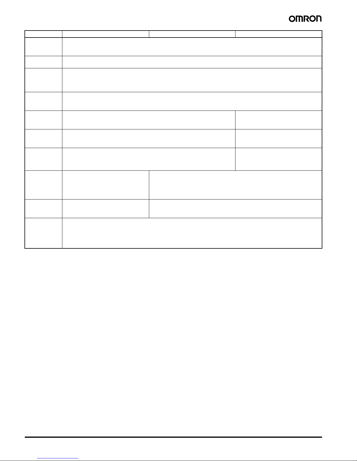
■Characteristics
Note: 1. The total error including the repeat accuracy, setting error, variation due to voltage change, and variation due to temperature change is
±0.01% ±0.05 s max.
2. The total time when power is not being supplied.
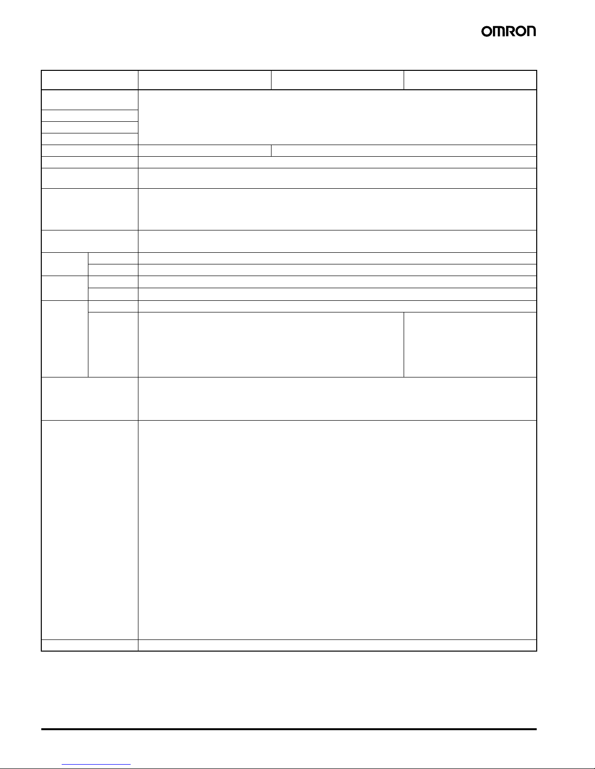
Item Weekly 2-circuit Models
(H5S-W@2)
Yearly 2-circuit Models
(H5S-Y@2)
Yearly 4-circuit Models
(H5S-Y@4)
Accuracy of operating
time
±0.01%±0.05 s max. (See note 1.)
The ±0.01% value applies to the set time interval.
Setting error
Influence of voltage
Influence of temperature
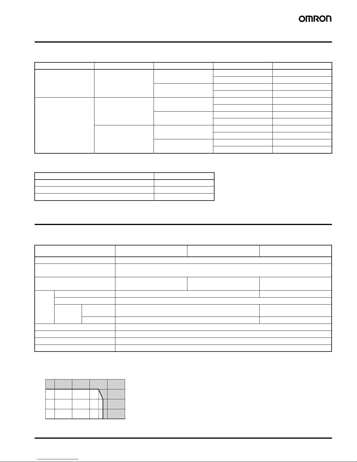
Cyclic error ±15 s per month (at 25°C) ±15 s per month (at −10 to 45°C), ±20 s per month (at 45 to 55°C)
Memory protection Continuous use: 5 years min. (at 25°C) (See note 2.)
Insulation resistance 100 MΩmin. (between current-carrying terminals and exposed non-current carrying metal parts, between operation
circuit and control output circuit, between control output circuits, and between non-continuous contacts.)
Dielectric strength 2,950 VAC, 50/60 Hz for 1 min (between current-carrying terminals and exposed non-current carrying metal parts)
2,000 VAC, 50/60 Hz for 1 min (between operation circuit and control output circuit, and between control output
circuits)
1,000 VAC, 50/60 Hz for 1 min (between non-continuous contacts)
Noise immunity ±1,500 V (between power terminals, for AC power models), ±500 V (between power terminals, for DC power models)
Square-wave noise by noise simulator (pulse width: 100 ns, for 1 µs, 1-ns rise time)
Vibration
resistance
Destruction 10 to 55 Hz with 0.375-mm single amplitude in 3 directions for 2 hours each
Malfunction 10 to 55 Hz with 0.25-mm single amplitude in 3 directions for 10 minutes each
Shock
resistance
Destruction 300 m/s23 times each in x, y, and z axes, 6 directions
Malfunction 100 m/s23 times each in x, y, and z axes, 6 directions
Life
expectancy
Mechanical 100,000 operations min.
Electrical 50,000 operations min. (15 A at 250 VAC, resistive load)
50,000 operations min. (10 A at 30 VDC, resistive load)
50,000 operations min. (10 A at 250 VAC, inductive load (cosφ= 0.7))
50,000 operations min. (1 HP at 250 VAC, motor load)
50,000 operations min. (100 W at 100 VAC, lamp load)
10,000 operations min. (300 W at 100 VAC, lamp load)
50,000 operations min. (3 A at 250
VAC, resistive load)
50,000 operations min. (3 A at 30
VDC, resistive load)
Approved standards cURus: UL 508/CSA C22.2 No.14,
Conforms to EN 60730-2-7(Pollution degree 2/overvoltage category II),
Conforms to VDE 0106/part100.
Conforms to Electrical Appliance and Material Safety Law (for Japan)
EMC (EMI) EN 60730-2-7
EMI Radiated: EN 60730-2-7 (CISPR 22 Class B)
EMI Conducted (Continuous): EN 60730-2-7 (CISPR 22 Class B)
EMI Conducted (Non-continuous): EN 60730-2-7 (CISPR 14-1)
Harmonic Current: EN 60730-2-7 (IEC 61000-3-2 Class A)
Voltage fluctuation/flicker: EN 60730-2-7 (IEC 61000-3-3)
(EMS) EN 60730-2-7
ESD Immunity: EN 60730-2-7 (IEC 61000-4-2): 6 kV contact discharge
8 kV air discharge
Radiated Electromagnetic Field Immunity: EN 60730-2-7 (IEC 61000-4-3): 10-V/m AM modulation
(80 MHz to 1 GHz, 1.4 GHz to 2 GHz)
10-V/m pulse modulation (900 MHz)
Conducted Disturbance Immunity: EN 60730-2-7 (IEC 61000-4-6): 10 V (0.15 to 80 MHz)
Burst Immunity: EN 60730-2-7 (IEC 61000-4-4): 2 kV power line
1 kV control line
Surge Immunity: EN 60730-2-7 (IEC 61000-4-5): 1 kV line to line (power line, output line)
2 kV line to ground (power line, output
line)
0.5 kV line to line (input line)
1 kV line to ground (input line)
Voltage Dip/Interrupting Immunity: EN 60730-2-7 (IEC 61000-4-11): 0.5-s cycle, 100% (rated voltage)
Weight Approx. 200 g