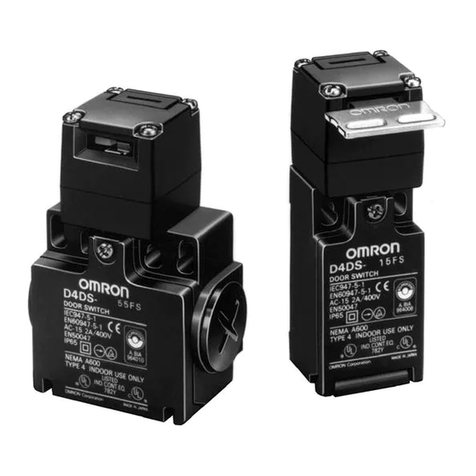
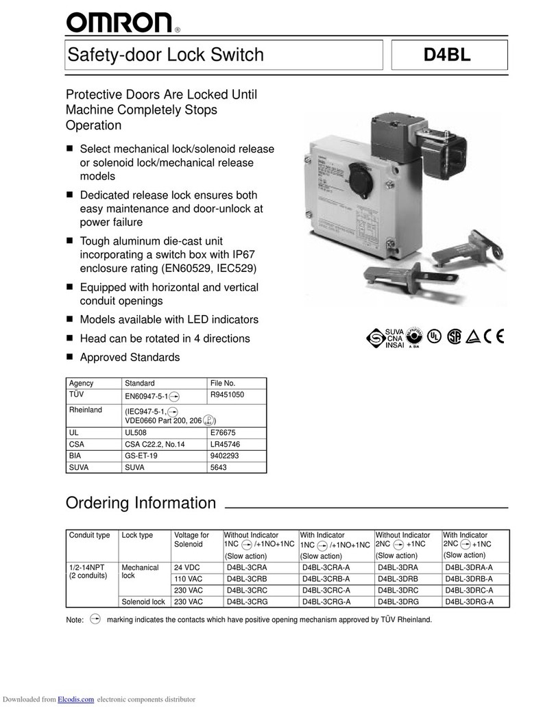
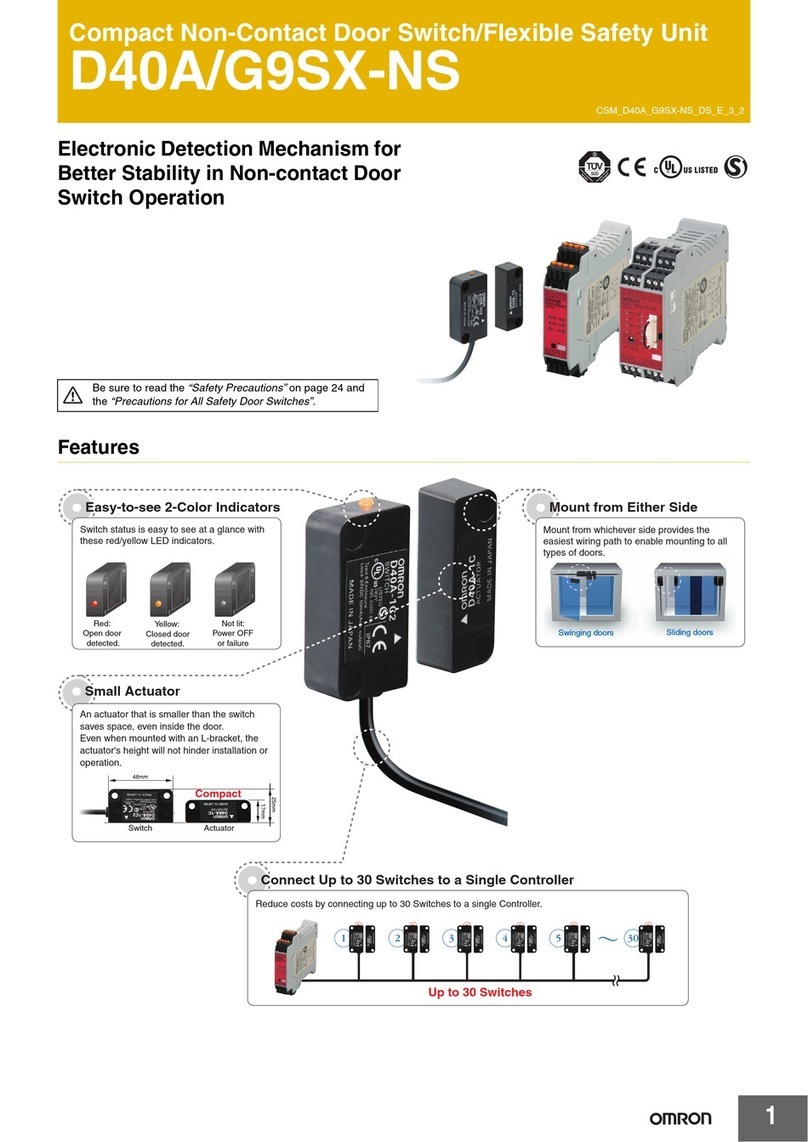
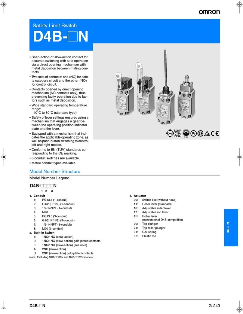
Omron D4D-R Series User manual

1
Manual Reset Limit Switch D4D-jR
A Series of Pull-reset Models Available
Ideal
for elevators (EN81), escalators (EN1
15), and
conveyors.
Positive opening mechanism and double
insulation approved by TÜV and BIA.
Approved by UL and CSA standards.
Switzerland’
s SUV
A approval pending.
Operates between –30°C and 70°C.
Safety Standards:
•Conformity:
Machinery Directive
Low V
oltage Directive
EN50047
EN1088
Approved Standards
Slow-action Models
Agency Standard File No.
TÜV Rheinland
EN60947-5-1
(Positive opening
approved.), EN81,
EN115
R9451193
UL (see note 1)
UL508
CSA C22.2 No.14
E76675
BIA (see note 2)
GS-ET-15
1-conduit: 9505895
2-conduit: 9509914
SUV
A (see note 2)
SUVA
1-conduit: 6013Z
2-conduit: 6012Z
Note: 1. CSA C22.2 No. 14 compliance was verified and ap-
proved
by UL (Marked with
).
2.
Except for adjustable roller lever models.
Eu
Ordering Information
Model Number Legend
D4D-jjjjR
123
1. Conduit
1: Pg13.5
(1-conduit)
2:
G1/2 (1-conduit)
3:
1/2-14NPT (1-conduit)
5:
Pg13.5 (2-conduit)
6:
G1/2 (2-conduit)
2. Built-in Switch
5: 1NC/1NO (Slow-action)
A: 2NC (Slow-action)
3. Actuator
20:
Roller lever
21:
Adjustable roller lever
27:
Adjustable roller lever (with rubber roller)
31: Plunger
32:
Roller plunger
62:
One-way roller arm lever (horizontal)
72:
One-way roller arm lever (vertical)

D4D-jRD4D-jR
2
List of Models
Actuator Conduit
size (see note 1)
1NC/1NO (Slow-action) 2NC (Slow-action)
Positive opening
(see note 2)
Model
Positive opening
(see note 2)
Model
Roller lever
1-conduit Pg13.5 D4D-1520R D4D-1A20R
oe ee
G1/2 D4D-2520R D4D-2A20R
1/2-14NPT D4D-3520R D4D-3A20R
2-conduit Pg13.5 D4D-5520R D4D-5A20R
G1/2 D4D-6520R D4D-6A20R
Adjustable roller lever
(S t 3)
1-conduit Pg13.5 D4D-1521R D4D-1A21R
djus ab e o e e e
(See note 3)
G1/2 D4D-2521R D4D-2A21R
1/2-14NPT D4D-3521R D4D-3A21R
2-conduit Pg13.5 D4D-5521R D4D-5A21R
G1/2 D4D-6521R D4D-6A21R
Adjustable roller lever
( ith bb ll )
1-conduit Pg13.5 D4D-1527R D4D-1A27R
djus ab e o e e e
(with rubber roller)
(See note 3)
G1/2 D4D-2527R D4D-2A27R
(S
ee no
t
e
3)
1/2-14NPT D4D-3527R D4D-3A27R
2-conduit Pg13.5 D4D-5527R D4D-5A27R
G1/2 D4D-6527R D4D-6A27R
Plunger 1-conduit Pg13.5 D4D-1531R D4D-1A31R
uge
G1/2 D4D-2531R D4D-2A31R
1/2-14NPT D4D-3531R D4D-3A31R
2-conduit Pg13.5 D4D-5531R D4D-5A31R
G1/2 D4D-6531R D4D-6A31R
Roller plunger
1-conduit Pg13.5 D4D-1532R D4D-1A32R
oepuge
G1/2 D4D-2532R D4D-2A32R
1/2-14NPT D4D-3532R D4D-3A32R
2-conduit Pg13.5 D4D-5532R D4D-5A32R
G1/2 D4D-6532R D4D-6A32R
One-way roller arm lever
(h i t l)
1-conduit Pg13.5 D4D-1562R D4D-1A62R
O e ay o e a e e
(horizontal) G1/2 D4D-2562R D4D-2A62R
1/2-14NPT D4D-3562R D4D-3A62R
2-conduit Pg13.5 D4D-5562R D4D-5A62R
G1/2 D4D-6562R D4D-6A62R
One-way roller arm lever
(til)
1-conduit Pg13.5 D4D-1572R D4D-1A72R
O e ay o e a e e
(vertical) G1/2 D4D-2572R D4D-2A72R
1/2-14NPT D4D-3572R D4D-3A72R
2-conduit Pg13.5 D4D-5572R D4D-5A72R
G1/2 D4D-6572R D4D-6A72R
Note: 1.
It is recommended that Pg13.5 be used for Switches for Europe and 1/2-14NPT for North America.
2.
The switches are marked with
indicating approval for the positive opening mechanism.
3.
The adjustable roller lever models are approved by the EN ratings (TÜV Rheinland) but not by GS-ET
-15 (BIA) and SUV
A.
D4D-jRD4D-jR
3
Specifications
Ratings
Applicable Standards
TÜV and BIA (EN60947-5-1)
Utilization
category
AC-15
Rated operating current (I
e)
2 A
Rated operating voltage (U
e)
400 V
UL (UL508/CSA C22.2 No.14)
A600
Rated
voltage
Carry current Current Volt-amperes
Ca y cu e
Make Break Make Break
120 V
AC
10 A 60 A
6 A
7,200 V
A
720 V
A
240 V
AC
30 A
3 A
480 V
AC
15 A
1.5 A
600 V
AC
12 A
1.2 A
Characteristics
Degree
of protection
IP65 (EN60947-5-1)
Life expectancy (see note)
Mechanical:
1,000,000 operations min.
Electrical:
150,000 operations min.
Operating speed
1 mm/s to 0.5 m/s
Contact gap
2 x 2 mm min.
Operating frequency
30 operations/min
Rated frequency
50/60 Hz
Insulation resistance
100 M
Ω
min. (at 500 VDC) between terminals of the same polarity
, and between each
terminal and non-current-carrying metal part
Contact resistance
25 m
Ω
max. (initial value)
Dielectric strength
Uimp
4 kV between terminals of the same polarity
, between terminals of dif
ferent polarity
,
and between each terminal and non-current-carrying metal part (EN60947-5-1)
Rated insulation voltage (U
i)
400 V (EN60947-5-1)
Switching overvoltage
1,500 V max. (EN60947-5-1)
Pollution degree
(operating environment)
3 (EN60947-5-1)
Short-circuit protective device (SCPD)
10 A, fuse type gI or gG (IEC269)
Conditional short-circuit current
100 A (EN60947-5-1)
Conventional enclosed thermal current
(Ithe)
10 A (EN60947-5-1)
Protection against electric shock Class II (double insulation)
V
ibration resistance
Malfunction:
10 to 55 Hz, 0.75-mm single amplitude
Shock resistance
Destruction:
1,000 m/s
2
min.
Malfunction:
300 m/s
2
min.
Ambient temperature
Operating: –30°
C to 70
°
C (with no icing)
Ambient humidity
Operating:
95% max.
Weight
Approx. 80 g (for D4D-1
120R)
Note: Life
expectancy values are calculated at an operating temperature of 5
°
C to 35
°
C, and an operating humidity of 40% to 70%.
Contact
your
OMRON sales representative for more detailed information on other operating environments.

D4D-jRD4D-jR
4
Operating Characteristics
1-conduit Models
Model D4D-1520R
D4D-2520R
D4D-3520R
D4D-1A20R
D4D-2A20R
D4D-3A20R
D4D-1521R
D4D-2521R
D4D-3521R
D4D-1A21R
D4D-2A21R
D4D-3A21R
(see
note 1)
D4D-1527R
D4D-2527R
D4D-3527R
D4D-1A27R
D4D-2A27R
D4D-3A27R
(see note 2)
D4D-1531R
D4D-2531R
D4D-3531R
D4D-1A31R
D4D-2A31R
D4D-3A31R
D4D-1532R
D4D-2532R
D4D-3532R
D4D-1A32R
D4D-2A32R
D4D-3A32R
D4D-1562R
D4D-2562R
D4D-3562R
D4D-1A62R
D4D-2A62R
D4D-3A62R
D4D-1572R
D4D-2572R
D4D-3572R
D4D-1A72R
D4D-2A72R
D4D-3A72R
LF max.
6.37 N 5.59 N 5.39 N
10.79 N 10.79 N
7.35 N 7.85 N
L
T max.
55°55°55°
4.5 mm 4.5 mm
7 mm 7 mm
PT1 max.
(see note 3)
18°
to 27
°18°
to 27
°18°
to 27
°
2 mm 2 mm 4 mm 4 mm
PT2
(see note 4)
(44°) (44°) (44°)
(2.9 mm) (2.9 mm) (5.2 mm) (4.3 mm)
OP --- --- --- 34±
0.5 mm
44.4±
0.8 mm
53±
0.8 mm
27±
0.8 mm
TT
(see note 5)
(70°) (70°) (70°)
(6 mm) (6 mm) (9 mm) (9 mm)
POF min.
(see note 6)
19.61 N 19.61 N 19.61 N 19.61 N 19.61 N 19.61 N 19.61 N
POT min.
(see note 6)
50°50°50°
3.2 mm 3.2 mm 5.8 mm 4.8 mm
Note: 1.
The operating characteristics of these switches were measured with the roller lever set at 30 mm.
2.
The operating characteristics of these switches were measured with the roller lever set at 31 mm.
3.
These PT1 values are possible when the NC contacts are OFF
.
4. These
PT2 values are possible when the NO contacts are ON (applicable to D4D-
j
R models with 1NC and 1NO contact each).
5. Reference
value.
6.
POT (positive opening travel) and POF (positive opening force) are required values for positive opening.
2-conduit Models
Model D4D-5520R
D4D-6520R
D4D-5A20R
D4D-6A20R
D4D-5521R
D4D-6521R
D4D-5A21R
D4D-6A21R
D4D-5527R
D4D-6527R
D4D-5A27R
D4D-6A27R
D4D-5531R
D4D-6531R
D4D-5A31R
D4D-6A31R
D4D-5532R
D4D-6532R
D4D-5A32R
D4D-6A32R
D4D-5562R
D4D-6562R
D4D-5A62R
D4D-6A62R
D4D-5572R
D4D-6572R
D4D-5A72R
D4D-6A72R
LF
max.
6.37 N 5.59 N 5.39 N
10.79 N 10.79 N
7.35 N 7.85 N
L
T max.
55°55°55°
4.5 mm 4.5 mm
7 mm 7 mm
PT1 max.
(see note 3)
18°
to 27
°18°
to 27
°18°
to 27
°
2 mm 2 mm 4 mm 4 mm
PT2
(see note 4)
(44°) (44°) (44°)
(2.9 mm) (2.9 mm) (5.2 mm) (4.3 mm)
OP --- --- --- 34±
0.5 mm
44.4±
0.8 mm
53±
0.8 mm
27±
0.8 mm
TT
(see note 5)
(70°) (70°) (70°)
(6 mm) (6 mm) (9 mm) (9 mm)
POF min.
(see note 6)
19.61 N 19.61 N 19.61 N 19.61 N 19.61 N 19.61 N 19.61 N
POT min.
(see note 6)
50°50°50°
3.2 mm 3.2 mm 5.8 mm 4.8 mm
Note: 1.
The operating characteristics of these switches were measured with the roller lever set at 30 mm.
2.
The operating characteristics of these switches were measured with the roller lever set at 31 mm.
3.
These PT1 values are possible when the NC contacts are OFF
.
4. These
PT2 values are possible when the NO contacts are ON (applicable to D4D-
j
R models with 1NC and 1NO contact each).
5. Reference
value.
6.
POT (positive opening travel) and POF (positive opening force) are required values for positive opening.

D4D-jRD4D-jR
5
Nomenclature
Head
With roller lever switches, the direction of the switch head
can be adjusted to any of the four directions by loosening
the roller lever switch screws at the four corners of the head.
Safety-oriented Lever Setting
Grooves which engage the lever every 90°are cut in the
operation indicator disk to prevent the lever from slipping
against the rotary shaft.
Cover
The cover, with a hinge on its lower part, can be opened by
removing the screw of the cover, which ensures ease of
maintenance and wiring.
Built-in Switch
Has a positive opening mechanism separating the con-
tacts when the contacts are welded.
Conduit
Wide switch variations.
Pg13.5: 1-conduit, 2-conduit models
G1/2: 1-conduit, 2-conduit models
1/2-14NPT: 1-conduit models
Reset Head
The direction of the reset head can be adjusted to any of
the four directions.
Note: The D4D-jR uses NBR.

D4D-jRD4D-jR
6
Operation
Contact Form
Model Contact Diagrams Remarks
D4D-j5jN 1NC/1NO
(slow-action) 11 12
23 24
Zb 11-12
23-24
Stroke
ON
Only NC contact 1
1-12 has an
approved positive opening
mechanism.
T
erminals numbers 1
1-12 and 23-24
can be used as unlike poles.
D4D-jAjN 2NC
(slow-action) 11
21
12
22
Zb 11-12
21-22
Stroke
ON
NC contacts 1
1-12 and 21-22 have an
approved positive opening
mechanism.
T
erminal numbers 1
1-12 and 21-22
can be used as unlike poles.
Note: T
erminals are numbered according to EN50013 and contacts are marked according to EN60947-5-1.
Positive Opening Mechanism
1NC/1NO Contact (Slow-action) 2NC Contact (Slow-action)
Contact spring
Return spring
Fixed contact (NC)
Movable contact
Plunger
Fixed contact (NO)
Contact spring
Return spring
Fixed contact (NC)
Movable contact
Plunger
Only
the NC contacts have a positive open
-
ing function.
When metal deposition occurs, the contacts
are separated from each other by pushing in
the plunger
.
Conforms to EN60947-5-1 Positive Opening
Both NC contacts have a positive opening
function.
When metal deposition occurs, the contacts
are separated from each other by pushing in
the plunger
.
Conforms to EN60947-5-1 Positive Opening
Note:
The switches are marked with “ ” indicating approval for the positive opening mechanism.

D4D-jRD4D-jR
7
Dimensions
Note: 1.
All units are in millimeters unless otherwise indicated.
2.
Unless otherwise specified, a tolerance of
±
0.4 mm applies to all dimensions.
3.
The minimum number of screw threads is five when the Pg13.5 conduit is used and four when the G1/2 conduit is used.
1-conduit Models
Roller Lever
D4D-1520R
D4D-2520R
D4D-3520R
D4D-1A20R
D4D-2A20R
D4D-3A20R
Adjustable Roller Lever
D4D-1521R
D4D-2521R
D4D-3521R
D4D-1A21R
D4D-2A21R
D4D-3A21R
Adjustable Roller Lever
(Rubber Roller Lever)
D4D-1527R
D4D-2527R
D4D-3527R
D4D-1A27R
D4D-2A27R
D4D-3A27R
17.5 dia. x 6.8
resin roller
R2.15±0.05
mounting holes
depth: 5
14 dia.
See note 3
on page
154.
Two. 4+0.15
0 dia. holes
20.5 x 20.5
17.5 dia. x 6.8
resin roller
R2.15±0.05
mounting holes
depth: 5
14 dia.
Two. 4+0.15
0 dia. holes
20.5
x 20.5
R20
to 65
R2.15±0.05
mounting holes
14 dia.
20.5
x 20.5
R31
to 65
50 dia. x 8
rubber roller
depth: 5
Two. 4+0.15
0 dia. holes
See note 3
on page
154.
See note 3
on page
154.

D4D-jRD4D-jR
8
Plunger
D4D-1531R
D4D-2531R
D4D-3531R
D4D-1A31R
D4D-2A31R
D4D-3A31R
Roller Plunger
D4D-1532R
D4D-2532R
D4D-3532R
D4D-1A32R
D4D-2A32R
D4D-3A32R
One-way Roller Arm Lever
(Horizontal)
D4D-1562R
D4D-2562R
D4D-3562R
D4D-1A62R
D4D-2A62R
D4D-3A62R
One-way Roller Arm Lever
(Vertical)
D4D-1572R
D4D-2572R
D4D-3572R
D4D-1A72R
D4D-2A72R
D4D-3A72R
14 dia.
R2.15±0.05
mounting holes
6 dia.
20.5
x 20.5
20.5 x 20.5
9.5 dia. x 5
resin roller
R2.15±0.05
mounting holes
depth: 5
Two. 4+0.15
0 dia. holes
14 dia.
depth: 5
Two. 4+0.15
0 dia. holes
12 dia. x 5
resin roller
R2.15±0.05
mounting holes
14 dia.
12 dia. x 5
resin roller
14 dia.
R2.15±0.05
mounting holes
depth: 5
Two. 4+0.15
0 dia. holes
depth: 5
Two. 4+0.15
0 dia. holes
See note 3
on page
154.
See note 3
on page
154.
See note 3
on page
154.
See note 3
on page
154.

D4D-jRD4D-jR
9
2-conduit Models
Roller Lever
D4D-5520R
D4D-6520R
D4D-5A20R
D4D-6A20R
Adjustable Roller Lever
D4D-5521R
D4D-6521R
D4D-5A21R
D4D-6A21R
Adjustable Roller Lever
(Rubber Roller Lever)
D4D-5527R
D4D-6527R
D4D-5A27R
D4D-6A27R
17.5 dia. x 6.8
resin roller
14 dia.
R2.15±0.05
mounting holes Cap
25
dia.
20.5 x 20.5
17.5 dia. x 6.8
resin roller
R20 to 65
R2.15±0.05
mounting holes
depth: 5
Two. 4+0.15
0 dia. holes
Cap
25
dia.
20.5 x 20.5
14 dia.
depth: 5
Two. 4+0.15
0 dia. holes
R2.15±0.05
mounting holes
depth: 5
Two. 4+0.15
0 dia. holes
Cap
25
dia.
14 dia.
R31 to 65
50 dia. x 8
rubber roller
20.5
x 20.5
See note 3
on page
154.
See note 3
on page
154.
See note 3
on page
154.

D4D-jRD4D-jR
10
Plunger
D4D-5531R
D4D-6531R
D4D-5A31R
D4D-6A31R
Roller Plunger
D4D-5532R
D4D-6532R
D4D-5A32R
D4D-6A32R
One-way Roller Arm Lever
(Horizontal)
D4D-5562R
D4D-6562R
D4D-5A62R
D4D-6A62R
One-way Roller Arm Lever
(Vertical)
D4D-5572R
D4D-6572R
D4D-5A72R
D4D-6A72R
R2.15±0.05
mounting holes
25
dia.
14 dia.
20.5
x 20.5
Cap
6 dia.
14 dia.
R2.15±0.05
mounting holes
depth: 5
Two. 4+0.15
0 dia. holes
Cap
25
dia.
20.5 x 20.5
9.5 dia. x 5
resin roller
12 dia. x 5
resin roller
14 dia.
R2.15±0.05
mounting holes
depth: 5
Two. 4+0.15
0 dia. holes
Cap
25
dia.
depth:
5
Two. 4+0.15
0 dia. holes
12 dia. x 5
resin roller
14 dia.
R2.15±0.05
mounting holes
depth: 5
Two. 4+0.15
0 dia. holes
Cap
25
dia.
See note 3
on page
154.
See note 3
on page
154.
See note 3
on page
154.
See note 3
on page
154.

D4D-jRD4D-jR
11
Levers
Refer
to the following for the angles and positions of the watchdogs.
Roller Lever
(D4D-jj20R)
Adjustable Roller Lever
(D4D-jj21R)
Adjustable Roller Lever
(Rubber Roller Lever)
(D4D-jj27R)
Sealed Plunger
(D4D-jj31R)
Roller Plunger
(D4D-jj32R)
One-way Roller Arm Lever
(Horizontal)
(D4D-jj62R)
One-way Roller Arm Lever
(Vertical)
(D4D-jj72R)
Dog
20
min.
10 min.
5 min.
Dog Dog
40 min.
10 min.
15 min.
45 min. 10 min.
25 min.
Dog
31 min.
Dog
Dog
20 min.
10 min.
Dog
41 min.
Dog
20 min.
30 max.
5.0 min.
10 min.
Dog
10 min.
5 min.
20 min.

D4D-jRD4D-jR
12
PrecautionsCAUTION
Do
not use metal connectors or conduits with this switch. Rigid
connectors and conduits may damage the switch. The broken
conduit hole may cause and electrical shock hazard.
If
the D4D-
j
R is applied to an emergency stop circuit or safety cir
-
cuit
for prevention of injury
, use the D4D-
j
R model that
has an NC
contact equipped with a force-separation mechanism, and make
sure
that the D4D-
j
R operates in the positive mode. Furthermore,
secure
the D4D-
j
R with screws or equivalent parts that are tight
-
ened in a single direction so that the D4D-jR cannot be easily
removed.
Then provide a protection cover for the D4D-
j
R and post
a
warning label near the D4D-
jR.
Ensure
that the actuator is pushed into the lock position by
, for ex
-
ample,
setting up a dog.
Not doing so may result in the actuator be
-
coming
unlocked and causing an accident.
When
the Limit Switch locks due to a fault in the system, be sure to
reset
the Limit Switch manually
before resupplying power after con
-
firming
the safety of the system.
Be sure to connect a fuse with a breaking current 1.5 to 2 times
larger
than the rated current to the Limit Switch in parallel in order to
protect
the Limit Switch from damage due to short-circuiting.
When using the Limit Switch for the EN ratings, use the gI or gG
10-A
fuse.
Do not use the Limit Switch as a stopper
.
Actuation
of the Limit Switch over a long time may deteriorate parts
of the Limit Switch and a releasing failure may result. Be sure to
check
the condition of the Limit Switch regularly
.
When using the Limit Switch as a safety component, be sure to
check
the system design for both operational and circuit safety
.
Correct Use
Operating Environment
The Limit Switch is intended for indoor use only. Using the Limit
Switch
outdoors may result in a malfunction.
Correct Tightening Torque
A
loose screw may result in a malfunction. Be sure to tighten each
screw
to the proper tightening torque as shown below
.
No. Type Torque
1 Terminal screw
0.59 to 0.78 N
S
m
2
Cover mounting
screw
0.78 to 0.88 N
S
m
3
Head mounting
screw
0.78 to 0.88 N
S
m
4
Lever mounting
screw
1.57 to 1.77 N
S
m
5
Switch mounting
screw (M4)
0.49 to 0.69 N
S
m
6 Connector
1.8 to 2.2 N
S
m
1.37 to 1.77 N
S
m (see note)
7
Cap screw
1.27 to 1.67 N
S
m
Note: This
applies to the 1/2-14NPT connector
.
Mounting
Fasten
the Switch with two M4 Allen-head bolts and washers. Pro
-
vide a stud with a diameter of 4-0.05/-0.15 and a height of 4.8 mm
max.
at two places as shown below so that the Switch is firmly fixed
at
four points.
Mounting hole
Mounting surface
Hole for stud insertion
4–0.05
–0.15 dia. height, 4.8 max.
Mounting
Holes/Studs
2-conduit
4–0.05
–0.15 dia. height, 4.8 max.
4–0.05
–0.15 dia. height, 4.8 max.
Standard 1-conduit
Changing the Head Direction
If the head direction has been changed, check the torque of each
screw and make sure that the screws are free of foreign sub-
stances,
and that each screw is tightened to the proper torque.

D4D-jRD4D-jR
13
Wiring
•Do
not connect the bare lead wires directly to the terminals but be
sure to connect each of them by using an insulation tube and
M3.5
round solderless terminals and tighten
each terminal screw
within
the specified torque range.
•
The proper lead wire is 20 to 14 A
WG (0.5 to 2.5 mm
2
) in size.
•Do
not touch the terminals
while power is being supplied in order
to
avoid an electrical shock.
dz dia. 3.7
D dia. 4.5
B: 7.0
L: 20.2
F: 7.7
ȏ:
9.0 (mm)
D dia.
dz dia.
Perform
wiring for the crimp terminals
in the orientation shown be
-
low,
so that they do not rest on the case or the cover
.
Crimp-style terminal
Terminal screw
Correct Incorrect
Crimp-style terminal
Correct
Incorrect
Processing the Conduit Opening
Tighten the connector to a torque of 1.8 to 2.2 N Sm (1.37 to
1.77 N
S
m
if it is a 1/2-14NPT). Excessive tightening torque may
damage
the casing. T
o satisfy IP65, apply sealing tape to the con
-
nector
conduit.
The diameter of the cable must be suited to the cor
-
responding
connector
.
Insert
a cap screw provided with the D4D-
j
R into any unused
con
-
duit
opening of the D4D-
j
R and tighten the cap screw to
a torque of
1.27
to 1.67 N
S
m.
Recommended Connector
Conduit
size
Manufacturer Model Applicable
cable diameter
G1/2 OMRON SC-6
7.5 to 9.0 mm
LAPP
(see note 1)
ST-PF1/2
5360-1002
6.0 to 12.0 mm
Ohm Denki
(see note 2)
OA-W1609
7.0 to 9.0 mm
Pg13.5 LAPP
(see note 1)
ST13.5
5301-5030
5.0 to 12.0 mm
1/2-14NPT LAPP
(see note 1)
ST-NPT1/2
5301-6030
6.0 to 12.0 mm
Note: 1.
LAPP is a German manufacturer
.
2.
Ohm Denki is a Japanese manufacturer
.
Maintenance and Repairs
The
user must not maintain or repair equipment incorporating any
D4D-jR
model. Contact the manufacturer of the equipment for any
maintenance
or repairs required.
ALL DIMENSIONS SHOWN ARE IN MILLIMETERS.
To
convert millimeters into inches, multiply by 0.03937. T
o convert grams into ounces, multiply by 0.03527.
Cat. No. C103-E1-2A
Other manuals for D4D-R Series
1
This manual suits for next models
70
Table of contents
Other Omron Switch manuals

Omron
Omron D4BL - User manual

Omron
Omron D4N-R - User manual

Omron
Omron D4JL-1NFA-C5 User manual

Omron
Omron A22LK Series User manual

Omron
Omron D4DH User manual

Omron
Omron D4JL Series User manual

Omron
Omron A165E - User manual

Omron
Omron E3G - User manual

Omron
Omron D40B - User manual

Omron
Omron D4MC-5000 User manual

Omron
Omron D5B - User manual

Omron
Omron D4MC User manual

Omron
Omron C2UW-L DA Series User manual

Omron
Omron D3C User manual

Omron
Omron D4A-N - User manual

Omron
Omron D4N Series User manual

Omron
Omron D4NS - User manual

Omron
Omron E3JM - User manual

Omron
Omron 61F-G1P User manual

Omron
Omron D4NH - User manual