Omron A165E - User manual

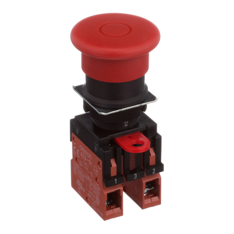
Emergency Stop Switch (16-dia.)
A165E
Separate Construction with Smallest
Class of Depth in the World
■Direct opening mechanism to open contacts in emergencies,
such as when they are welded.
■Conforms to EN418.
■Includes a safety lock to prevent misuse.
■Features separate construction that allows the Switch to be
separated for easier wiring and one-piece-like construction
that allows easier handling.
■Models available with 3 contacts built into a single block
(A165E-U).
Model Number Structure
List of Models
Model Number Legend (Completely Assembled).........................Shipped as a set that includes the Operation Unit
and light source.
Diameter of
Operation Unit Function Model Shape
30-mm models
40-mm models
Push-Lock,
turn-reset
A165E Separate
construction
(30-mm model)
A165E-@-03U One-piece
construction
(30-mm model)
Be sure to read the precautions for all pushbutton switches
in the Pushbutton Switches Group Catalog (Cat. No. X032),
as well as the “Safety Precautions” on page 9.
S
LS
M
LM
None
24D
01
IP65 (Oil-resistant)
02
03U
2. Light Source
1. Operation Unit Shape and Functions
Code
30 dia.
40 dia.
3. Contacts
Code Description
SPST-NC
DPST-NC
TPST-NC *
*TPST-NC models have
one-piece construction with
the contact unit. Only
non-lighted models are
available.
Note: Models with separate construction
(SPST-NC and DPST-NC) are for
normal loads only. One-piece models
(TPST-NC) are for either normal loads
or microloads.
Non-lighted
Lighted
Non-lighted
Lighted
Push-lock,
turn-reset
Code
Non-lighted
LED 24 VDC 24 VDC
--- ---
Functions
Type Operation
voltage Rated
voltage
Pushbutton
LS 24D 02
http://www.ia.omron.com/ 1
(c)Copyright OMRON Corporation 2007 All Rights Reserved.

A165E
Ordering Information
List of Sets
List of Sets (in Different Colors)
* Models with yellow or gray pushbutton colors cannot be used as emergency switches.
Individual Parts (for Switches with Separate Construction)
Operation Units
Lamps
Sockets
Socket Units
Illumination Rated voltage
Pushbutton color
Pushbutton size Terminal Contact form Model
LED 24 VDC
Red
30 dia.
Solder terminal
SPST-NC A165E-LS-24D-01
DPST-NC A165E-LS-24D-02
Non-lighted --- SPST-NC A165E-S-01
DPST-NC A165E-S-02
LED 24 VDC
40 dia.
SPST-NC A165E-LM-24D-01
DPST-NC A165E-LM-24D-02
Non-lighted --- SPST-NC A165E-M-01
DPST-NC A165E-M-02
Non-lighted --- 30 dia. TPST-NC A165E-S-03U
40 dia. A165E-M-03U
Illumination Pushbutton color * Pushbutton size Terminal Contact form Model
Non-lighted
Yellow
30 dia.
Solder terminal
SPST-NC A165E-SY-01
Gray A165E-SGR-01
Yellow DPST-NC A165E-SY-02
Gray A165E-SGR-02
Yellow
40 dia.
SPST-NC A165E-MY-01
Gray A165E-MGR-01
Yellow DPST-NC A165E-MY-02
Gray A165E-MGR-02
Yellow 30 dia.
TPST-NC
A165E-SY-03U
Gray A165E-SGR-03U
Yellow 40 dia. A165E-MY-03U
Gray A165E-MGR-03U
Appearance Illumination Model
30
dia. Non-lighted A165E-S
Lighted A165E-LS
40 dia. Non-lighted A165E-M
Lighted A165E-LM
Appearance LED color Rated
voltage Model
Red Bright
5VDC A16-5DSR
12 VDC A16-12DSR
24 VDC A16-24DSR
Appearance Illumination Contact
form Model
Non-lighted SPST-NC A165E-01
DPST-NC A165E-02
Lighted SPST-NC A165E-01L
DPST-NC A165E-02L
Appearance Illumination Contact
form Model
Lighted SPST-NC A165E-R-24D-01
DPST-NC A165E-R-24D-02
http://www.ia.omron.com/ 2
(c)Copyright OMRON Corporation 2007 All Rights Reserved.

A165E
Accessories (Order Separately)
Specifications
Certified Standard Ratings
UL508, CSA C22.2 No.14, CCC(GB14048.5)
Models with Separate Construction
Models with One-piece Construction
TÜV(EN60947-5-1)
Models with Separate Construction
Models with One-piece Construction
Certified Standards
* Certification for CSA C22.2 No. 14 is indicated by the mark.
Switch Ratings
Models with Separate Construction
Minimum applicable load: 5 VDC, 150 mA
Models with One-piece Construction
Minimum applicable load: 5 VDC, 1 mA
LED Ratings
(Only for Models with LEDs)
Item Appearance Type Model Precautions
Yellow Plate Yellow, 45 dia. A16Z-5070 Use this as an emergency stop
nameplate.
Panel Plug Round A16ZT-3003
Used for covering the panel cutouts
for future panel expansion.
Degree of protection: IP40
Color: Black
Tightening Tool --- A16Z-3004 Useful for repetitive mounting. Be
careful not to tighten excessively.
Extractor A16Z-5080 Convenient for extracting the Switch
and Lamp.
Rated voltage Resistive load
125 VAC
250 VAC
30 VDC
5 A
3 A
3 A
Rated voltage Resistive load
125 VAC
250 VAC
30 VDC
1 A
0.5 A
1 A
Rated voltage Resistive load
250 VAC
30 VDC
3 A
3 A
Rated voltage Resistive load
250 VAC
30 VDC
0.5 A
1 A
Certification body Standards File No.
UL * UL508,
CSA C22.2 No.14 E41515
TÜV Product Service EN60947-5-1,
EN60947-5-5 Inquire
CQC (CCC) GB14048.5 2003010303070678
Rated voltage Resistive load
125 VAC
250 VAC
30 VDC
5 A
3 A
3 A
Rated voltage Resistive load
125 VAC
250 VAC
30 VDC
1 A
0.5 A
1 A
Rated voltage Rated current Operation voltage
24 VDC 10 mA 24 VDC±5%
http://www.ia.omron.com/ 3
(c)Copyright OMRON Corporation 2007 All Rights Reserved.

A165E
Characteristics
*1.LED not mounted. (Test them with the LED removed.)
*2.Degree of protection from the front of the panel.
Operating Characteristics
Structure and Nomenclature
Type
Item
Emergency Stop Switch
Non-lighted
A165E-S/A165E-M Lighted
A165E-LS/A165-LM
Non-lighted,
One-piece construction
A165E-U
Allowable operating
frequency
Mechanical 20 operations/minute max.
Electrical 10 operations/minute max.
Insulation resistance 100 M:min. (at 500 VDC)
Dielectric strength
Between terminals of same polarity 1,000 VAC, 50/60 Hz for 1 min
Between terminals of different
polarity 2,000 VAC 50/60 Hz for 1 min
Between each terminal and ground 2,000 VAC 50/60 Hz for 1 min
Between lamp terminals 1,000 VAC, 50/60 Hz for 1 min *1 ---
Vibration resistance Malfunction 10 to 55 Hz, 1.5-mm double amplitude (malfunction within 1 ms)
Shock resistance
Destruction 500 m/s2
Malfunction 300 m/s2max.
(malfunction within 1 ms)
150 m/s2max.
(malfunction within 1 ms)
Durability Mechanical 100,000 operations min.
Electrical 100,000 operations min.
Degree of protection IP65 Oil-resistant *2 IP65 *2 IP65 Oil-resistant *2
Electric shock protection class Class II
PTI (tracking characteristic) 175
Degree of contamination 3 (EN60947-5-1)
Weight Approx. 16 g (in case of DPST-NC Switches)
Ambient operating temperature 10 to 55qC (with no icing or condensation)
Ambient operating humidity 35% to 85%
Ambient storage temperature 25 to 65qC (with no icing or condensation)
Type
Item Characteristics of models
with separate construction Characteristics of models
with one-piece construction
Operating force OF max. 14.7 N 14.7 N
Releasing force RF min. 0.1 N·m 0.1 N·m
Pretravel PT 3.5r0.5 mm 3r0.5 mm
Color
Operation Unit Color
• Models with LED illumination: Red
• Non-lighted models * : Red, yellow, or gray
Degree of Protection
IP65 oil resistance
Specifications
For standard load
125 VAC, 5 A
250 VAC, 3 A
30 VDC, 3 A
Operation Unit
Socket
(The above figure is example of the
separate construction model.)
* Models with yellow or gray pushbutton colors cannot be used as emergency switches.
http://www.ia.omron.com/ 4
(c)Copyright OMRON Corporation 2007 All Rights Reserved.

A165E
Dimensions (Unit: mm)
22.1±0.8
10.8±5
A165E-S
Mounting ring
Lock ring
Lock
Packing (t=0.5)
16+0.2 dia.
0
3+0.1 dia.
0
30 dia.
Non-lighted models
30 mm diameter
7.8+0.3
0
Panel cutout
dimensions
·When applying a coating such as
paint to the panel, dimensions
after the coating must satisfy the
specified dimensions.
·Recommended panel thickness:
0.5 to 3.2 mm.
M16 × 1
16+0.2 dia.
0
3+0.1 dia.
0
Lock ring
Lock
Packing (t=0.5)
Mounting ring
30 dia.
A165E-LS
Lighted models
30 mm diameter
0
7.8+0.3
Panel cutout
dimensions
·When applying a coating such as
paint to the panel, dimensions
after the coating must satisfy the
specified dimensions.
·Recommended panel thickness:
0.5 to 3.2 mm.
M16 × 1
22.1±0.8
21.5±0.5
A165E-S-03U
Mounting ring
Packing (t=0.5)
Lock ring
Mounting ring
16+0.2 dia.
03+0.1 dia.
0
30 dia.
7.8+0.3
0
Panel cutout
dimensions
·When applying a coating such as
paint to the panel, dimensions
after the coating must satisfy the
specified dimensions.
·Recommended panel thickness:
0.5 to 3.2 mm.
Non-lighted,
One-piece construction models
30 mm diameter M16 × 1
http://www.ia.omron.com/ 5
(c)Copyright OMRON Corporation 2007 All Rights Reserved.

A165E
M16 ×1
10.8±0.5
21.1±0.8
28.5±0.8
20±0.8
1.42.6
0.5
12.3
15.8
2.8
12.1
18
A165E-M
Mounting ring
Lock ring
Lock
Packing (t=0.5)
40 dia.
Switch
Non-lighted models
40 mm diameter
16+0.2 dia.
0
3+0.1 dia.
0
7.8+0.3
0
Panel cutout
dimensions
·When applying a coating such as
paint to the panel, dimensions
after the coating must satisfy the
specified dimensions.
·Recommended panel thickness:
0.5 to 3.2 mm.
M16 ×1
0.5
12.3
15.8
2.8
6.05
18
A165E-LM
Mounting ring
Lock ring
Lock
Packing (t=0.5)
40 dia.
Switch
Lighted models
40 mm diameter
16+0.2 dia.
0
3+0.1 dia.
0
7.8+0.3
0
Panel cutout
dimensions
·When applying a coating such as
paint to the panel, dimensions
after the coating must satisfy the
specified dimensions.
·Recommended panel thickness:
0.5 to 3.2 mm.
M16 ×1
21.5±0.5 1
A165E-M-03U
Mounting ring
Lock ring
40 dia.
Lock
Packing (t=0.5)
One-piece construction models
40 mm diameter
3+0.1 dia.
0
16+0.2 dia.
0
7.8+0.3
0
Panel cutout
dimensions
·When applying a coating such as
paint to the panel, dimensions
after the coating must satisfy the
specified dimensions.
·Recommended panel thickness:
0.5 to 3.2 mm.
http://www.ia.omron.com/ 6
(c)Copyright OMRON Corporation 2007 All Rights Reserved.

A165E
Accessories
Terminal Arrangement
Note: The L+ and Lterminals are not available with the non-lighted models.
Yellow Plate (Vinyl Chloride)
Lock Ring
Panel Plugs (Round Type)
A16ZT-3003
xSelect an appropriate Panel Plug according to the panel design and
mount from the front side of the panel. Panel cutout dimensions are
the same as those for the Switch.
Tightening Tool
t=1
A16Z-5070
15.6 dia.
45 dia.
12 ×12
15.8 ±0.1 dia.
Rough surface
15 dia. 0
−0.1
Rough
surface
18 dia.
A16Z-3004
18 dia.
SPST Switches DPST Switches TPST Switches
NC1
NC1
L−
L+
SW1
NC1 NC2
NC2
NC1
L−
L+
SW1 SW2
NC2
NC1
NC3
Stopper
http://www.ia.omron.com/ 7
(c)Copyright OMRON Corporation 2007 All Rights Reserved.

A165E
Installation
Mounting to the Panel (Models with Separate Construction)
After installing the Operation Unit, snap in the Switch from the back of the panel.
(1) Installing the Operation Unit
(2) Mounting the Switch (3) Removing the Switch
xSnap on the Switch to the Operation Unit.
xMake sure that the Switch has the correct orientation when snapping it onto the
Operation Unit.
xAlign the white dot on the Operation Unit with the guide groove on the side of
the Switch marked with an “L” as shown below, and push the Switch into the
Operation Unit until it clicks into place. Confirm that the Switch is securely in
place before using.
xInsert the prongs of the A16Z-5080 Extractor between the Switch and the
Operation Unit, grip the Switch, and pull to remove.
(4) Installing the LED Lamp
xWhen mounting the Lamp, make sure it is facing the direction shown in the
following diagram. Insert the Lamp while matching the protruding part of the
Lamp and the small guides on the outer surface of the casing.
Panel
Mounting nut
Lock ring
Rubber packing or Yellow Plate (sold separately)
Edge
Lock
Cutout
Panel
Mounting nut
Lock hole
Lock ring
Rubber packing
(included with the
product) or Yellow
Plate (sold separately)
xAttach rubber packing or the Yellow Plate
onto the Switch from its terminal side.
Insert the Switch into the panel from the
front. Install the lock ring and mounting
nut from the terminal side and tighten.
xAdjust the slits on the hole of rubber
packing and Yellow Plate to the
protruding part of the Unit.
xRubber packing is not necessary when
the Yellow Plate is used.
xTighten the nut to the torque of 0.29 to
0.49 N·m.
xCasing should be installed with its
protruding part adjusted to the slit of the
panel hole.
xAlign the lock ring to the groove of the
casing so that the edge is drawn to the
panel side.
White dot
Guide groove
L marking Extractor (A16Z-5080)
Narrow guide
Protruding part Wide guide
http://www.ia.omron.com/ 8
(c)Copyright OMRON Corporation 2007 All Rights Reserved.

A165E
Safety Precautions
Be sure to read the precautions for all pushbutton switches in the Pushbutton Switches Group Catalog (Cat. No. X032).
!CAUTION
If the Operation Unit is separated from the Socket Unit, the
equipment will not stop, creating a hazardous condition.
Always confirm that safety functions are operating before
starting operation.
Mounting
xAlways make sure that the power is turned OFF before mounting,
removing, or wiring the Switch, or performing maintenance.
Electrical shock or fire may result if the power is not turned OFF.
xThe tightening torque is 0.29 to 0.49 N·m.
Wiring
xBe sure to use electrical wires that are a size appropriate for the
applied voltage and carry current. Perform soldering according to
the conditions given below. If the soldering is not properly
performed, abnormal heating may result, possibly resulting in fire.
1. Hand soldering: 30 W, within 5 s
2. Dip soldering: 240qC, within 3 s
Wait for one minute after soldering before exerting any external
force on the solder.
xUse non-corrosive resin fluid as the flux.
xMake sure that the electric cord is wired so that it does not touch
the Unit. If the electric cord will touch the Unit, then electric wires
with a heat resistance of 100qC min. must be used.
xAfter wiring the Switch, maintain an appropriate clearance and
creepage distance.
Operating Environment
xThe IP65 model is designed with a degree of protection so that it
will not sustain damage if it is subjected to water from any direction
to the front of the panel.
xThe Switch is intended for indoor use only. Using the Switch
outdoor may cause it to fail.
Using the Microload
xInsert a contact protection circuit, if necessary, to prevent the
reduction of life expectancy due to extreme wear on the contacts
caused by loads where inrush current occurs when the contact is
opened and closed.
xThe A165E-@U (one-piece construction) allows both a standard
load (125 V at 1 A, 250 V at 0.5 A) and a microload. If a standard
load is applied, however, the microload area cannot be used. If the
microload area is used with a standard load, the contact surface
will become rough, and the opening and closing of the contact for
a microload may become unreliable.
xThe minimum applicable load is the N-level reference value. This
value indicates the malfunction reference level for the reliability
level of 60% (O60) (conforming to JIS C5003).
The equation, O60 = 0.5 x 10⁶/time indicates that the estimated
malfunction rate is less than 1/2,000,000 with a reliability level of
60%.
LEDs
xThe LED current-limiting resistor is built-in, so external resistance
is not required.
Operating Torque
xDo not exceed an operating torque of 0.49 N·m in the direction of
rotation.
xDo not pull the operating button or apply excessive force to any
side of the button.
Otherwise it may be damaged.
Others
xThe oil-resistant IP65 uses NBR rubber and is resistant to general
cutting oil and cooling oil. Some special oils cannot be used with
the oil-resistant IP65, however, so contact your OMRON
representative for details.
xIf the panel is to be coated, make sure that the panel meets the
specified dimensions after coating.
xDue to the structure of the Switch, severe shock or vibration may
cause malfunctions or damage to the Switch.
Also, most Switches are made from resin and will be damaged if
they come into contact with sharp objects. Particularly scratches
on the Operation Unit may create visual and operational obtrusions.
Handle the Switches with care, and do not throw or drop them.
Precautions for Correct Use
0.15 mA
1 mA
Area of use
Voltage (V)
Current (mA)
Invalid
area
Rated voltage Internal limiting resistor
24 VDC 2000 :
Screwdriver
Hammer
Do not allow the
Switch to drop and hit
the floor.
Do not place or drop
heavy objects on the
Switch.
Do not operate the
Switch with hard or
sharp objects.
http://www.ia.omron.com/ 9
(c)Copyright OMRON Corporation 2007 All Rights Reserved.
http://www.ia.omron.com/ C-1
(c)Copyright OMRON Corporation 2007 All Rights Reserved.
Safety Precautions for All Pushbutton Switches
For the individual precautions for a Switch, refer to the Safety Precautions in the section for that Switch.
Do not perform wiring with power supplied to the
Switch. Do not touch the terminals or other charged
parts of the Switch while power is being supplied.
Doing so may result in electric shock.
Do not apply a voltage between the incandescent lamp
and the terminal that is greater than the rated voltage.
Doing so may damage the lamp or LED and cause the
Operation Unit to pop out.
Always turn OFF the power and wait for 10 minutes
before replacing the incandescent lamp. If the lamp is
replaced immediately after the power is turned OFF,
the remaining heat may cause burns.
For details, refer to the Precautions for Correct Use in the
Technical Guide for Pushbutton Switches.
WARNING
Caution
Precautions for Correct Use

http://www.ia.omron.com/ C-2
(c)Copyright OMRON Corporation 2007 All Rights Reserved.
Technical Guide for Pushbutton Switches
Precautions for Correct Use of Pushbutton Switches
●For the individual precautions for a Switch, refer to the precautions in the section for that Switch.
Electrical Characteristics
1. Operating Load
xThe switching load capacity of the Switch greatly varies between
AC and DC. Always be sure to apply the rated load. The control
capacity will drastically drop if it is a DC load. This is because a DC
load has no current zero-cross point, unlike an AC load. Therefore,
if an arc is generated, it may continue for a comparatively long time.
Furthermore, the current direction is always the same, which
results in a contact relocation phenomena whereby the contacts
easily stick to each other and do not separate when the surfaces of
the contacts are uneven.
x
Some types of load have a great difference between normal current
and inrush current. Make sure that the inrush current is within the
permissible value. The greater the inrush current in the closed circuit
is, the greater the contact abrasion or shift will be. Consequently,
contact weld, contact separation failures, or insulation failures may
result. Furthermore, the Switch may be broken or damaged.
x
If the load is inductive, counter-electromotive voltage will be generated.
The higher the voltage is, the higher the generated energy will be,
which will increase the abrasion of the contacts and contact relocation
phenomena. Be sure to use the Switch within the rated conditions.
Inrush Current
xApproximate control capacities are given in ratings tables, but
these alone are insufficient to guarantee correct operation. For
special types of load, with unusual switching voltage or current
waveforms, test whether correct operation is possible with the
actual load before application.
xWhen switching for microloads (voltage or current), use a Switch
with microload specifications. The reliability of silver-plated
contacts, which are used in Switches for standard loads, will be
insufficient for microloads.
x
When switching microloads or very high loads that are beyond the
switching capacity of the Switch, connect a relay suitable for the load.
Type of Load vs. Inrush Current
All the performance ratings given are for operation under the following
conditions unless otherwise specified.
Inductive load
: A minimum power factor of 0.4 (AC) and a maximum
time constant of 7 ms (DC)
Lamp load: An inrush current 10 times higher than the steady-state
current
Motor load: An inrush current 6 times higher than the steady-state
current
Note: Inductive loads can cause problems especially in DC circuitry. Therefore,
it is essential to know the time constants (L/R) of the load.
2. Load Connections
Do not contact a single Switch to two power supplies that are different
in polarity or type.
Connection of Different Polarities
The power supply may short-circuit if the loads are connected in the
way shown in the "incorrect" example below.
Even in the "correct" example, note that the insulation performance of
the switch may deteriorate and the switch life may be shortened
because loads are connected to both contacts.
Connection of Different Power Supplies
The DC and AC power may be mixed for the circuit shown below.
Do not design a circuit where voltage is imposed between contacts,
otherwise contact weld may result.
t
o (Steadystate
current)
i (Inrush current)
I
(A)
t
Relay
(Approxi-
mately 4 to 5
times higher)
Motor
(Approximately
5 to 10 times
higher)
Incandescent
lamp (Approximately 10 to 15 times
higher)
Solenoid
(Approximately 10 to 20 times higher)
I
(A)
Load
Load
Load
Load
Incorrect
correct
Connect the load to the same polarity.
Load
Load
AC
DC
Incorrect
Load
100 V
200 V
Incorrect

http://www.ia.omron.com/ C-3
(c)Copyright OMRON Corporation 2007 All Rights Reserved.
Technical Guide for Pushbutton Switches
3. Contact Protective Circuit
Apply a contact protective circuit to extend the contact life, prevent
noise, and suppress the generation of carbide or nitric acid. Be sure
to apply the contact protective circuit correctly, otherwise an adverse
effect may occur. The following provides typical examples of contact
protective circuits. If the Limit Switch is used in an excessively humid
location for switching a load that easily generates arcs, such as an
inductive load, the arcs may generate NOx, which will change into
HNO3if it reacts with moisture. Consequently, the internal metal parts
may corrode and the Limit Switch may fail. Be sure to select the ideal
contact preventive circuit from the following.
Typical Examples of Contact Protective Circuits
Do not apply contact protective circuits as shown below.
4. Switching
x
Do not use the Switch for loads that exceed the rated switching capacity or other
contact ratings. Doing so may result in contact weld, contact separation failures,
or insulation failures. Furthermore, the Switch may be broken or damaged.
xDo not touch the charged switch terminals while power is supplied,
otherwise an electric shock may be received.
xThe life of the Switch varies greatly with switching conditions.
Before using the Switch, be sure to test the Switch under actual
conditions. Make sure that the number of switching operations is
within the permissible range. If a deteriorated Switch is used
continuously, insulation failures, contact weld, contact failures,
switch damage, or switch burnout may result.
xDo not apply excessive or incorrect voltages to the Switch or
incorrectly wire the terminals. Otherwise, the Switch may not
function properly and have an adverse effect on external circuitry.
Furthermore, the Switch itself may become damaged or burnt.
xDo not use the Switch in locations where flammable or explosive
gases are present. Otherwise switching arcs or heat radiation may
cause a fire or explosion.
xDo not drop or disassemble the Switch, otherwise it may not be
capable of full performance. Furthermore, it may be broken or
burnt.
Circuit example
Applicable
current
Feature and details Element selection
AC DC
CR circuit
*Yes *When AC is switched, the load impedance
must be lower than the CR impedance.
C: 1 to 0.5 PFuswitching current (A)
R: 0.5 to 1 :uswitching voltage (V)
The values may change according to the
characteristics of the load. The capacitor
suppresses the spark discharge of current
when the contacts are open. The resistor
limits the inrush current when the contacts
are closed again. Consider the roles of the
capacitor and resistor and determine ideal
capacitance and resistance values through
testing. Basically, use a capacitor with a
dielectric strength between 200 and 300 V.
When AC is switched, make sure that the
capacitor has no polarity.
Yes Yes
The operating time will be greater if the load
is a relay or solenoid. Connecting the CR
circuit in parallel to the load is effective when
the power supply voltage is 24 or 48 V and in
parallel to the contacts when the power
supply voltage is 100 to 200 V.
Diode method No Yes
Energy stored in the coil is changed into
current by the diode connected in parallel to
the load. Then the current flowing to the coil
is consumed and Joule heat is generated by
the resistance of the inductive load. The
reset time delay with this method is longer
than that in the CR method.
The diode must withstand a peak inverse
voltage 10 times higher than the circuit
voltage and a forward current as high or
higher than the load current.
Diode and
Zener diode
method
No Yes
This method will be effective if the reset time
delay caused by the diode method is too
long.
Use a Zener diode with a Zener voltage that
is approximately 1.2 upower supply voltage
as, depending on the environment, the load
may not operate.
Varistor
method Yes Yes
This method makes use of constant-voltage
characteristic of the varistor so that no
high-voltage is imposed on the contacts.
This method causes a reset time delay.
Connecting a varistor in parallel to the load is
effective when the supply voltage is 24 to 48
V and in parallel to the contacts when the
supply voltage is 100 to 200 V.
---
This circuit effectively
suppresses arcs when the
contacts are OFF. The
capacitor will be charged,
however, when the contacts
are OFF. Consequently,
when the contacts are ON
again, short-circuited current
from the capacitance may
cause contact weld.
This circuit effectively sup-
presses arcs when the
contacts are OFF. When the
contacts are ON again,
however, charge current will
flow to the capacitor, which
may result in contact weld.
C
Power
supply
Inductive
load
R
C
Inductive
load
Power
supply
R
Inductive
load
Power
supply
Inductive
load
Power
supply
Inductive
load
Power
supply
Switching a DC inductive load is usually
more difficult than switching a resistive
load. By using an appropriate contact
protective circuit, however, switching a DC
inductive load will be as easy as switching a
resistive load.
Load
Power
supply
CLoad
Power
supply
C

http://www.ia.omron.com/ C-4
(c)Copyright OMRON Corporation 2007 All Rights Reserved.
Technical Guide for Pushbutton Switches
Mechanical Conditions
Operating Force and Operating Method
xFingertip operation is an important feature of Pushbutton Switches.
In terms of Switch operation, Pushbutton Switches differ greatly
from detection switches such as Microswitches. Operating the
Switch using a hard object (e.g., metal), or with a large or sudden
force, may deform or damage the Switch, resulting in faulty or rough
operation, or shortening of the Switch life. The strength varies with
the size and construction of the Switch. Use the appropriate Switch
for the application after confirming the operating method and
operating force with this catalog.
xThe pushbutton surface is composed of resin. Therefore, do not
attempt to operate the pushbutton using a sharp object, such as a
screwdriver or a pair of tweezers. Doing so may damage or deform
the pushbutton surface and result in faulty operation.
Mounting
xSwitches can be broadly divided into two categories according to
mounting method: panel-mounting models and PCB-mounting
models. Use the appropriate model for the mounting method
required. Basically, panel-mounting Switches can withstand a
greater operating force than PCB-mounting Switches. If, however,
the panel thickness or the panel-cutout dimensions are not suitable
for the Switch, it may not be able to withstand the normal operating
force. With continuous mounting in particular, select a panel of a
thickness that is easily sufficient to withstand the total operating
force.
xPanel-mounting Switches can be divided into two categories
according to the mounting method: snap-in mounting models and
screw-mounting models. Snap-in mounting Switches are held in
place with the elasticity of resin or a metal leaf spring. Do not
attempt to modify the spring after mounting. Doing so may result in
faulty operation or damage the mounting structure. Mount screw-
mounting models using the screws and nuts provided (or
individually specified). Tighten the screws to the specified torque.
Mounting with different screws or nuts, or tightening beyond the
specified torque may result in distortion of the inside of the case or
damage to the screw section.
xSubjecting the Switch to severe vibrations or shock may result in
faulty operation or damage. Also, many of the Switches are
composed of resin so contact with sharp objects may result in
damage to the surface. This kind of damage may spoil the
appearance of the Switch or result in faulty operation. Do not throw
or drop the Switch.
Hammer
Do not apply
excessive or
sudden force.
Do not use
sharp objects.
Screwdrive
r
Tweezers
Do not attempt to
modify the spring
after mounting.
Use the
screws and
nuts provided
(or specified).
Snap-in Mounting Screw Mounting
Do not drop or
knock the Switch.
Do not drop object
s
or place
heavy objects on
the Switch.
Hammer Screwdriver
Do not operate the
Switch with heavy
or sharp objects.

http://www.ia.omron.com/ C-5
(c)Copyright OMRON Corporation 2007 All Rights Reserved.
Technical Guide for Pushbutton Switches
Mounting Precautions
Wiring
•
Perform wiring so that the lead wires will not be caught on other objects
as this will cause stress on the Switch terminals. Wire the Switch so
that there is slack in the lead wires and fix lead wires at intermediate
points. If the panel to which the Switch is mounted needs to be opened
and closed for maintenance purposes, perform wiring so that the
opening and closing of the panel will not interfere with the wiring.
•With miniature Switches, the gap between the terminals is very
narrow. Use protective or heat-absorbing tubes to prevent burning
of the wire sheath or shorting.
Soldering
•There are two methods for soldering the Switch: hand soldering and
automatic soldering. In addition, automatic soldering itself can be
divided into two types : dip soldering and reflow soldering. Use the
soldering method appropriate for the mounting method.
Typical Soldering Example
•Do not use soldering flux that contains chlorine. Doing so may
result in metal corrosion.
•Perform hand soldering using the appropriate soldering iron.
•With the exception of PCB-mounting Switches, when performing
hand soldering, hold the Switch so that the terminals point
downwards so that flux does not get inside the Switch.
•Leave a gap of at least 1 mm between the soldered parts and the
surface of the case so that flux does not get inside the Switch.
•When applying flux using a brush, use a sponge soaked in flux as
shown below. Do not apply more than is necessary. Also, apply the
flux with the PCB inclined at an angle of less than 80°so that flux
does not flow onto the mounting surface of the Switch.
Method Soldering device Application
Hand soldering Soldering iron
Small quantities
Different materials
Lead wire terminals
Automatic
soldering
Dip
soldering
Jet soldering bath
Dip soldering bath
Large quantities of
discrete terminals
Reflow
soldering
Infrared reflow (IR)
soldering bath
Vapor-phase (VPS)
reflow soldering bath
Large quantities
of miniature SMD
terminals
Protective tube
lTermina
Lead wire
Large-capacity
soldering iron
Small-capacity
soldering iron
used for a long
time
Perform soldering for
between 3 to 5 s with
a suitable soldering iron.
Case
Terminal
Solder 1 mm min.
Lead wire
Flux
Sponge
soaked in flux
Brush
Brush
80°
max.

http://www.ia.omron.com/ C-6
(c)Copyright OMRON Corporation 2007 All Rights Reserved.
Technical Guide for Pushbutton Switches
•Do not place PCBs that have had flux applied or have been
soldered on top of each other. Otherwise, the flux on the PCBs
solder surface may stain the upper part of the Switch or even
permeate the inside of the Switch and cause contact failure.
Be sure to insert a special PCB stocker.
•When performing soldering with a dip soldering bath, ensure that
the flux does not reach a higher level than the PCB.
•Flux is especially likely to rise up at the edges of the PCB. If the
Switch is mounted near the edge of the PCB, create a gap between
the edge by using a split PCB, and insert the PCB in the soldering
bath so that the edge that is farthest from the Switch enters the bath
first.
Storage
•When the Switch is left unused or stored for long periods, the
ambient conditions can have a great effect on the condition of the
Switch. In certain environments, leaving the Switch exposed may
result in deterioration (i.e., oxidation, or the creation of an oxide
film) of the contacts and terminals, causing the contact resistance
to increase, and making it difficult to solder the lead wires.
Therefore, store in a well-ventilated room, inside, for example, a
non-hygroscopic case, in a location where no corrosive gases are
present.
•If the Switch is stored in a location where it will be exposed to direct
light, colored resin in the colored plate may fade. Therefore, do not
store the Switch in locations where it will be exposed to direct light.
Flux
Do not place PCBs
with solder or flux on
top of each other.
Create distance
Split PCB
Create distance
Insert in soldering
bath from this
edge.
Flux is more likely
to rise at the edges.

This catalog is a guide to help customers select the proper safety products. Observe the following items when choosing
products, select the right products for your devices or equipment, and develop a safety-related system to fully utilize product
functions.
Setting Up a Risk Assessment System
The items listed in this catalog must be used properly in terms of product location as well as product performance and
functionality. Part of the process of selecting and using these products should include the introduction and development of a
risk assessment system early in the design development stage to help identify potential dangers in your equipment that will
optimize safety product selection. A badly designed risk assessment system often results in poor choices when it comes to
safety products.
• Related International Standards:
ISO 14121 Principles of Risk Assessment
Safety Policy
When developing a safety system for the devices and equipment that use safety products, make every effort to understand
and conform to the entire series of international and industrial standards available, such as the examples given below.
• Related International Standards:
ISO 12100 Basic Concepts, General Principles for Design
IEC 61508 Functional Safety of Electrical/Electronic/Programmable Electronic Safety-related Systems
Role of Safety Products
Safety products have functions and mechanisms that ensure safety as defined by standards. These functions and
mechanisms are designed to attain their full potential within safety-related systems. Make sure you fully understand all
functions and mechanisms, and use that understanding to develop systems that will ensure optimal usage.
• Related International Standards:
ISO 14119 Interlocking Devices Associated with Guards-Principles for Design and Selection
Installing Safety Products
Make sure that properly educated and trained engineers are selected to develop your safety-related system and to install
safety products in devices and equipment.
• Related International Standards:
ISO 12100 Basic Concepts, General Principles for Design
IEC 61508 Functional Safety of Electrical/Electronic/Programmable Electronic Safety-related Systems
Observing Laws and Regulations
Safety products should conform to pertinent laws, regulations, and standards, but make sure that they are used in
accordance with the laws, regulations, and standards of the country where the devices and equipment incorporating these
products are distributed.
• Related International Standards:
IEC 60204 Electrical Equipment of Machines
Observing Usage Precautions
Carefully read the specifications and precautions listed in this catalog for your product as well as all items in the Operating
Manual packed with the product to learn usage procedures that will optimize your choice. Any deviation from precautions
will lead to unexpected device or equipment failure not anticipated by safety-related systems or fire originating from
equipment failure.
Transferring Devices and Equipment
When transferring devices and equipment, be sure to keep one copy of the Operating Manual and pack another copy with
the device or equipment so the person receiving it will have no problem operating it.
• Related International Standards:
ISO 12100 Basic Concepts, General Principles for Design
IEC 61508 Functional Safety of Electrical/Electronic/Programmable Electronic Safety-related Systems
WARNING
http://www.ia.omron.com/ (c)Copyright OMRON Corporation 2007 All Rights Reserved.
2007.11
OMRON Corporation
Industrial Automation Company
http://www.ia.omron.com/ (c)Copyright OMRON Corporation 2007 All Rights Reserved.
In the interest of product improvement, specifications are subject to change without notice.
Read and Understand This Catalog
Please read and understand this catalog before purchasing the products. Please consult your OMRON representative if you have any questions or
comments.
Warranty and Limitations of Liability
WARRANTY
OMRON's exclusive warranty is that the products are free from defects in materials and workmanship for a period of one year (or other period if
specified) from date of sale by OMRON.
OMRON MAKES NO WARRANTY OR REPRESENTATION, EXPRESS OR IMPLIED, REGARDING NON-INFRINGEMENT, MERCHANTABILITY, OR
FITNESS FOR PARTICULAR PURPOSE OF THE PRODUCTS. ANY BUYER OR USER ACKNOWLEDGES THAT THE BUYER OR USER ALONE
HAS DETERMINED THAT THE PRODUCTS WILL SUITABLY MEET THE REQUIREMENTS OF THEIR INTENDED USE. OMRON DISCLAIMS ALL
OTHER WARRANTIES, EXPRESS OR IMPLIED.
LIMITATIONS OF LIABILITY
OMRON SHALL NOT BE RESPONSIBLE FOR SPECIAL, INDIRECT, OR CONSEQUENTIAL DAMAGES, LOSS OF PROFITS, OR COMMERCIAL
LOSS IN ANY WAY CONNECTED WITH THE PRODUCTS, WHETHER SUCH CLAIM IS BASED ON CONTRACT, WARRANTY, NEGLIGENCE, OR
STRICT LIABILITY.
In no event shall responsibility of OMRON for any act exceed the individual price of the product on which liability is asserted.
IN NO EVENT SHALL OMRON BE RESPONSIBLE FOR WARRANTY, REPAIR, OR OTHER CLAIMS REGARDING THE PRODUCTS UNLESS
OMRON'S ANALYSIS CONFIRMS THAT THE PRODUCTS WERE PROPERLY HANDLED, STORED, INSTALLED, AND MAINTAINED AND NOT
SUBJECT TO CONTAMINATION, ABUSE, MISUSE, OR INAPPROPRIATE MODIFICATION OR REPAIR.
Application Considerations
SUITABILITY FOR USE
OMRON shall not be responsible for conformity with any standards, codes, or regulations that apply to the combination of products in the customer's
application or use of the product.
At the customer's request, OMRON will provide applicable third party certification documents identifying ratings and limitations of use that apply to the
products. This information by itself is not sufficient for a complete determination of the suitability of the products in combination with the end product,
machine, system, or other application or use.
The following are some examples of applications for which particular attention must be given. This is not intended to be an exhaustive list of all possible
uses of the products, nor is it intended to imply that the uses listed may be suitable for the products:
• Outdoor use, uses involving potential chemical contamination or electrical interference, or conditions or uses not described in this catalog.
• Nuclear energy control systems, combustion systems, railroad systems, aviation systems, medical equipment, amusement machines, vehicles, safety
equipment, and installations subject to separate industry or government regulations.
• Systems, machines, and equipment that could present a risk to life or property.
Please know and observe all prohibitions of use applicable to the products.
NEVER USE THE PRODUCTS FOR AN APPLICATION INVOLVING SERIOUS RISK TO LIFE OR PROPERTY WITHOUT ENSURING THAT THE
SYSTEM AS A WHOLE HAS BEEN DESIGNED TO ADDRESS THE RISKS, AND THAT THE OMRON PRODUCT IS PROPERLY RATED AND
INSTALLED FOR THE INTENDED USE WITHIN THE OVERALL EQUIPMENT OR SYSTEM.
Disclaimers
CHANGE IN SPECIFICATIONS
Product specifications and accessories may be changed at any time based on improvements and other reasons.
It is our practice to change model numbers when published ratings or features are changed, or when significant construction changes are made.
However, some specifications of the product may be changed without any notice. When in doubt, special model numbers may be assigned to fix
or establish key specifications for your application on your request. Please consult with your OMRON representative at any time to confirm actual
specifications of purchased product.
DIMENSIONS AND WEIGHTS
Dimensions and weights are nominal and are not to be used for manufacturing purposes, even when tolerances are shown.
ERRORS AND OMISSIONS
The information in this catalog has been carefully checked and is believed to be accurate; however, no responsibility is assumed for clerical,
typographical, or proofreading errors, or omissions.
PERFORMANCE DATA
Performance data given in this catalog is provided as a guide for the user in determining suitability and does not constitute a warranty. It may represent
the result of OMRON’s test conditions, and the users must correlate it to actual application requirements. Actual performance is subject to the OMRON
Warranty and Limitations of Liability.
PROGRAMMABLE PRODUCTS
OMRON shall not be responsible for the user's programming of a programmable product, or any consequence thereof.
COPYRIGHT AND COPY PERMISSION
This catalog shall not be copied for sales or promotions without permission.
This catalog is protected by copyright and is intended solely for use in conjunction with the product. Please notify us before copying or reproducing this
catalog in any manner, for any other purpose. If copying or transmitting this catalog to another, please copy or transmit it in its entirety.
Other manuals for A165E -
1
This manual suits for next models
22
Table of contents
Other Omron Switch manuals

Omron
Omron D4CC-1001 User manual

Omron
Omron D4D-R Series User manual

Omron
Omron D41D User manual

Omron
Omron D4SL-N Series User manual

Omron
Omron D4SL-N N Series User manual

Omron
Omron G9SR User manual

Omron
Omron D4BL - User manual

Omron
Omron D40ML Series User manual

Omron
Omron D4NL - User manual

Omron
Omron D4BL - User manual

Omron
Omron D4GL-1AFA-A4 User manual

Omron
Omron D4DL User manual

Omron
Omron A3AA-90K1-00 User manual

Omron
Omron D40A-G9SX-NS - User manual

Omron
Omron WL - User manual

Omron
Omron D4BL - User manual

Omron
Omron A4E User manual

Omron
Omron D40Z User manual

Omron
Omron SS Series User manual

Omron
Omron 61F-G User manual