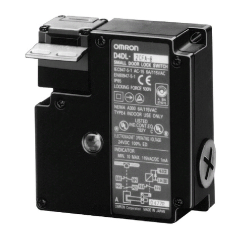
Omron D4MC User manual

1
Enclosed Switch D4MC
Economical, High Utility Enclosed
Switch
High precision and long life (10,000,000 mechani-
cal
operations) through employment of the moving
spring used in OMRON Z Basic Switch.
Sealed with gasket diaphragm to provide high
sealing
property without use
of any adhesive or pin.
Suitable for applications demanding higher me-
chanical
strength, dustproof and drip-proof proper
-
ties than those on basic switches.
Panel mount versions have the same operating
position as Z Basic Switch.
Resin molded terminal versions are available. RC
Ordering Information
Model Number Legend
D4MC-
1
1. Actuator
5000:
Panel mount plunger
5020:
Panel mount roller plunger
5040:
Panel mount crossroller plunger
1020:
Short hinge lever
1000:
Hinge lever
2000:
Hinge roller lever
2020:
Short hinge roller lever
3030:
One-way action short hinge roller lever
List of Models
Actuator Model
Panel
mount plunger
D4MC-5000
Panel mount roller plunger
D4MC-5020
Panel mount crossroller plunger
D4MC-5040
Short hinge lever
D4MC-1020
Hinge lever
D4MC-1000
Hinge roller lever
D4MC-2000
Short hinge roller lever
D4MC-2020
One-way action short hinge roller lever
D4MC-3030
Note: 1.
Use molded terminal models (refer to page 209) when using the Switch under one of the following conditions:
a) dusty
, b) high amount of dripping oil, or c) high humidity
2.
Micro-load models are available.
e.g. Standard model
Micro-load model
D4MC-5020 D4MC-5020-C

D4MC D4MC
2
Specifications
Ratings
Rated
voltage
Non-inductive load
Inductive load
Resistive load
Lamp load
Inductive load
Motor load
NC NO NC NO NC NO NC NO
125 V
AC
10 A
3 A
1.5 A
10 A
5 A
2.5 A
250 V
AC
10 A
2.5 A
1.25 A
10 A
3 A
1.5 A
480 V
AC
3 A
1.5 A
0.75 A
2.5 A 1.5 A
0.75 A
8 VDC
10 A
3 A
1.5 A
6 A 5 A
2.5 A
14 VDC
10 A
3 A
1.5 A
6 A 5 A
2.5 A
30 VDC
6 A 3 A
1.5 A
5 A 5 A
2.5 A
125 VDC
0.5 A 0.4 A
0.05 A 0.05 A
250 VDC
0.25 A
0.2 A
0.03 A 0.03 A
Inrush current
NC
30 A max.
us cu e
NO
15 A max.
Note: 1.
The above figures are for steady-state currents.
2.
Inductive loads have a power factor of 0.4 min. (AC) and a time constant of 7 ms max. (DC).
3.
Lamp load has an inrush current of 10 times the steady-state current.
4.
Motor load has an inrush current of 6 times the steady-state current.
5.
The above ratings were tested under the following conditions according to JIS C4508.
Ambient temperature:
20±2°C
Ambient humidity:
65±5%
Operating frequency:
20 operations/min
Approved Standard Ratings
UL/CSA
A300
Rated
voltage
Carry current Current Volt-amperes
a ed o age
Ca y cu e
Make Break Make Break
120 V
AC
10 A 60 A
6 A
7,200 V
A
720 V
A
240 V
AC
0
30 A
3 A
,00
0
Micro load:
0.1 A, 125 V
AC
0.1 A, 30 VDC
EN60947-1 and EN60947-5-1
250
V
, 10 A (AC-12)

D4MC D4MC
3
Characteristics
Degree
of protection
IP67 (NEMA250: 6.6P)
Life expectancy
Mechanical:
10,000,000 operations min.
Electrical:
500,000 operations min.
Operating speed
0.05 mm/s to 0.5 m/s (at panel mount plunger)
Operating frequency
Mechanical:
120 operations/min
Electrical:
20 operations/min
Insulation resistance
100 M
Ω
min. (at 500 VDC)
Contact resistance
15 m
Ω
max. (initial value)
Dielectric strength
1,000 V
AC, 50/60 Hz for 1 min between terminals of the same polarity
2,000 V
AC, 50/60 Hz for 1 min between current-carrying metal parts and ground, and between
each terminal and non-current-carrying part
Rated insulation voltage (U
i)
1,000 V
AC
Pollution degree
(operating environment)
3 (IEC947-5-1)
Protection against electric shock
Class II
PTI (tracking characteristics)
175
Switch category
D (IEC335)
Rated operating current (I
e)
10 A
Rated operating voltage (U
e)
250 V
AC
V
ibration resistance
Malfunction: 10 to 55 Hz, 1.5-mm double amplitude (see note)
Shock resistance
Destruction:
1,000 m/s
2
min.
Malfunction:
100 m/s
2
min. (in case of plunger) (see note)
Ambient temperature
Operating: –10
°
C to 80
°
C (with no icing)
Ambient humidity
Operating: 35% to 95%
Weight
Approx. 71 g (at panel mount plunger)
Note:
Less than 1 ms under a free state at the operating limits.
Approved Standards
(Except Molded Terminal Models)
UL (File No. E76675)/CSA (File No. E45258)
Operating Characteristics
Model D4MC-5000 D4MC-5020 D4MC-5040 D4MC-1020 D4MC-1000 D4MC-2000 D4MC-2020 D4MC-3030
OF
max. 5.88 N
5.88 N 2.55 N 1.67 N 1.96 N 2.94 N 2.94 N
RF min.
0.98 N 0.98 N 0.34 N 0.25 N 0.39 N 0.39 N 0.39 N
PT max.
1.6 mm 1.6 mm
--- --- --- --- ---
OT min.
5 mm 5 mm
2.5 mm
4 mm 5 mm 2 mm 2 mm
MD
max.
0.2 mm 0.2 mm 1.7 mm
3 mm 3 mm
1.5 mm 1.5 mm
OP 21.8±
1.2 mm
33.4±
1.2 mm
25±
1 mm
25±
1 mm
40±
1 mm
40±
1 mm
50±
1 mm
FP max.
--- ---
33 mm 36 mm 51 mm 47 mm
57.2 mm

D4MC D4MC
4
Engineering Data (Reference Data)
Mechanical Life Expectancy (D4MC-5000)
Life expectancy (x 10 operations)
4
Overtravel
(mm)
Operating temperature: 20±2°C
Operating humidity: 65±5%
No load
Operating frequency: 120 operations/min
Electrical Life Expectancy
Life expectancy (x 10 operations)
4
Operating temperature: 20±2°C
Operating humidity: 65±5%
Operating frequency: 20 operations/min
10,000
5,000
2,000
1,000
500
200
100
0.01 0.02 0.05 0.1 0.2 0.5 1 2 5 10
10,000
7,000
5,000
3,000
1,000
700
500
300
100
70
50
30
10 10 1286420
125 VAC cosφ=1
125 VAC cosφ=0.4
250 VAC cosφ=1
250 VAC cosφ=0.4
Operation
Contact Form
COM NO NC
Dimensions
Note: 1. All
units are in millimeters unless otherwise indicated.
2.
Unless otherwise specified, a tolerance of
±
0.4 mm applies to all dimensions.
Panel Mount Plunger
D4MC-5000
Note: 1. Stainless steel plunger
2. The length of the imperfect
threads is 1.5 mm maximum.
M12 x 1 mounting screw
Two hexagon nuts
(thickness: 3
width: 17)
Two, 4.3±0.1 dia.
mounting holes
Seal rubber (NBR)
Terminal
protective
cover
22
max.
(See
note 2)
(See
note 1)
8.4
dia.
(21 x 21)
15
16
dia.
Panel Mount Roller Plunger
D4MC-5020
Note: 1. Stainless steel roller
2. The length of the imperfect
threads is 1.5 mm maximum.
12.7 dia. ×5 (see note 1)
(See
note
2)
M12 x 1 mounting screw
Two hexagon nuts
(thickness: 3
width: 17)
Terminal
protective
cover Two, 4.3±0.1 dia.
mounting holes Seal rubber (NBR)
22
max.
(21 x 21)
15
16
dia.

D4MC D4MC
5
Panel Mount Crossroller Plunger
D4MC-5040
Note: 1. Stainless steel roller
2. The length of the imperfect
threads is 1.5 mm maximum.
22
max.
16
dia.
M12 x 1 mounting screw
Two hexagon nuts
(thickness: 3
width: 17)
(See
note
2)
Terminal
protective
cover Two,
4.3
±0.1 dia.
mounting holes Seal rubber (NBR)
12.7 dia. ×
5
(see note 1)
(21
x 21)
Short Hinge Lever
D4MC-1020
Note: Stainless steel lever
t = 1 (see note)
Terminal
protective
cover Two, 4.3±0.1 dia.
mounting holes Seal rubber (NBR)
(21
x 21)
22 max.
15
Hinge Lever
D4MC-1000
Note: Stainless steel lever
t = 1 (see note)
Terminal
protective
cover
Two, 4.3±0.1 dia.
mounting holes Seal rubber (NBR)
(21
x 21)
22 max.
15
Hinge Roller Lever
D4MC-2000 12.7 dia. ×
7.5
(see note 2)
Terminal
protective
cover
Two, 4.3±0.1 dia.
mounting holes Seal rubber (NBR)
t = 1
(see note 1)
(21
x 21)
22 max.
Note: 1. Stainless steel lever
2. Plastic roller
15
Short Hinge Roller Lever
D4MC-2020
Note: 1. Stainless steel lever
2. Plastic roller
t = 1
(see note 1)
12.7 dia. ×
7.5
(see note 2)
Terminal
protective
cover
Two, 4.3±0.1 dia.
mounting holes Seal rubber (NBR)
(21
x 21)
22 max.
15

D4MC D4MC
6
One-way Action Short Hinge Roller Lever
D4MC-3030
Mounting
Holes
Two 4.3 dia. mounting holes or
M4 screw holes
25.4 ±0.15
Note: 1. Stainless steel lever
2. Plastic roller
12.7 dia. ×
7.5
(see note 2)
t = 1
(see note 1)
Terminal
protective
cover Two, 4.3±0.1 dia.
mounting holes Seal rubber (NBR)
Angle
of roller
swing: 90°
(21 x 21)
22 max.
15
14
Molded Terminal Models
The
molded terminal model is available with right-hand, left-hand and underside leads and is recommended for use where the Switch is ex
-
posed
to dust, oil, or moisture.
(2)
(3)
(1)
When
placing your order for the
Switch specify the required length
of
V
.C.T
. cable in addition to the model number of the Switch
Example:
Standard type:
D4MC-5040
Location of lead outlet:
Underside
Length of lead:
1 m (V
.C.T
. lead)
When placing your order for the above Switch specify the model
number
as D4MC-5043 (V
.C.T 1 m)
Suffix by Location of Lead Outlet
Location of lead outlet
Model
COM, NC, and NO
Right-hand D4MC-jjj1
Left-hand D4MC-jjj2
Underside D4MC-jjj3
Leads Supplied
Leads Nominal
cross-sectional
area
Finished outside diameter
Terminal
connections
Standard length
V.C.T
. (V
inyl cabtire cable)
1.25 mm
2T
riple conductor:
10.5 mm dia.
Black: COM
White: NO
Red: NC
1, 3, 5 m
Terminal Protective Cover
ZC55
Terminal Cover (ZC55-0002H):
The following three parts are supplied as a set.
Rubber packing
Terminal cover Seal rubber
ZC
Seal Rubber (SC-1404C)

D4MC D4MC
7
Precautions
Correct Use
Operating Method
Excessive dog angle, operating speed, or overtravel (OT) may
damage the actuator. Check that OT has a sufficient margin. The
actual
OT should be rated OT x 0.7 to 1.
Handling
•Do not expose the Switch to water exceeding 60°C or use it in
steam.
•Do
not use the Switch in oil or water
.
•
An 8.5- to 10.5-dia. cable can be applied
as seal rubber for the
lead
wire outlet. (Use two- or three-core cable
of VCT1.25 mm
2.)
•When detaching the Terminal Protective Cover, insert a
screwdriver and apply a force in the opening direction. Do not
use excess force to remove the cover. Doing so may cause
deformation
in the fitting section and reduce the holding force.
Screwdriver
T
erminal Protective Cover
When
mounting
the T
erminal Protective Cover to the case, align the
cover
on the case and then press the cover down to mount
it firmly
. If
the
cover is pressed down in an inclined position, rubber packing will
deform
and thus af
fect the sealing capability
.
Rubber packing Rubber packing
Mounting
When
mounting the Switch with screws on
a side surface, fasten the
Switch with M4 screws and use washers, spring washers, etc., to
ensure
secure mounting.
Mounting Holes
T
wo, 4.3-dia. or M4 screw holes
•When mounting the Panel Mount-type Switch (DCMC-5000,
D4MC5020, or D4MC5040) with screws on a side surface,
remove
the hexagonal nuts from the actuator
.
•When
mounting the
panel mount type on a panel, be careful not
to tighten to an excessive torque. Tightening the screws to a
torque
exceeding 4.91 N
S
m will cause the plunger to fail.
Mounting Hole Dimensions
12.5+0.2
0dia. 12.5+0.2
0dia.
5+0.2
0
13+0.2
0
D4MC-5000
D4MC-5020, D4MC5040
Correct Tightening Torque
A loose screw may cause malfunctions. Be sure to tighten each
screw
to the proper tightening torque as shown in the table.
No. Type Torque
1 T
erminal screw
0.78 to 1.18 N
S
m
2
Panel mounting screw
2.94 to 4.92 N
S
m
3
Side mounting screw
1.18 to 1.47 N
S
m
ALL DIMENSIONS SHOWN ARE IN MILLIMETERS.
To
convert millimeters into inches, multiply by 0.03937. T
o convert grams into ounces, multiply by 0.03527.
Cat. No. C027-E1-7
Table of contents
Other Omron Switch manuals

Omron
Omron D4BL - User manual

Omron
Omron D4MC-5000 User manual

Omron
Omron D4GL-1AFA-A4 User manual

Omron
Omron C2UW-L DA Series User manual

Omron
Omron D4BL - User manual

Omron
Omron D2MQ Series User manual

Omron
Omron A22TK User manual

Omron
Omron D4BL - User manual

Omron
Omron ER1022 User manual

Omron
Omron D41D User manual