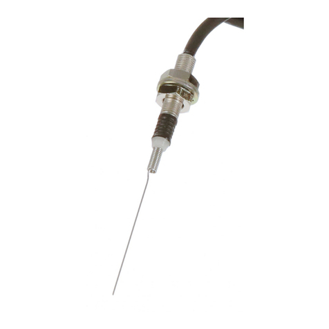
Omron D3C User manual

254
Ultra Subminiature Detection Switch D3C
Ultra Subminiature Detection Switch
with Slide Mechanism and Lever
Actuator
Compact (8 6 4.2 mm (W H D)) and light
(approximately 0.3 g) with long, 3-mm stroke.
Built-in slide mechanism allows selection of
shorting or non-shorting timing to match the
application.
Ideal for a wide variety of applications, including
compact household appliances, audio equipment,
office machines, and telecommunications equip-
ment.
Ordering Information
Model Number Legend
D3C-j2j0
12
1. Switching Timing
1: Non-shorting
2: Shorting
2. Maximum Oprating Force
1: 1.28 N {130 gf}
2: 0.39 N {40 gf}
List of Models
Actuator OF 1.28 N {130 gf} OF 0.39 N {40 gf}
Non-shorting Model Shorting Model Non-shorting Model Shorting Model
Rotary lever D3C-1210 D3C-2210 D3C-1220 D3C-2220
Specifications
Ratings
Electrical ratings 0.1 A at 30 VDC (resistive load)
Note: The ratings values apply under the following test conditions:
Ambient temperature: 20±2°C
Ambient humidity: 65±5%
Operating frequency: 30 operations/min

D3C D3C
255
Characteristics
Operating speed 1 to 500 mm/s
Operating frequency Mechanical: 200 operations/min max.
Electrical: 30 operations/min max.
Insulation resistance 100 MΩmin. (at 250 VDC)
Contact resistance (initial value) 50 mΩmax.
Dielectric strength 250 VAC, 50/60 Hz for 1 min between terminals of same polarity
250 VAC, 50/60 Hz for 1 min between current-carrying metal parts and ground
Vibration resistance Malfunction: 10 to 55 Hz, 1.5-mm double amplitude
Shock resistance Destruction: 1,000 m/s2{approx. 100G} max.
Malfunction: 300 m/s2{approx. 30G} max.
Durability (see note 2) 50,000 operations min. (30 operations/min)
Degree of protection IEC IP00
Degree of protection against
electric shock Class III
Proof tracking index (PTI) 175
Ambient operating temperature –20°C to 80°C (at ambient humidity of 60% max.) (with no icing)
Ambient operating humidity 85% max. (for 5°C to 35°C)
Weight Approx. 0.3 g
Note: 1. The data given above are initial values.
2. For testing conditions, consult your OMRON sales representative.
Contact Specifications
Contact Specification Slide
Material Silver plated
Minimum applicable load
(see note) 1 mA at 5 VDC
Note: For more information on the minimum applicable load, refer to Using Micro Loads on page 257.
Contact Form
(3) (1) (2)
NO COM NC
SPDT

D3C D3C
256
Dimensions
Mounting Holes
Note: All units are in millimeters unless otherwise indicated.
4±0.1
1.6 dia5.7±0.1
M1.6 tap
Dimensions and Operating Characteristics
Note: 1. All units are in millimeters unless otherwise indicated.
2. Unless otherwise specified, a tolerance of ±0.4 mm applies to all dimensions.
D3C-1210/-2210
D3C-1220/-2220
64.7
3.5
2.5 2.5 0.8
4
8
8.7
6.7
0.3
0.9
1.6
4.2
5.6
1
1R
5.7±0.15
4±0.15
OP FP
1-dia. hole
1.5 0
–0.15 dia.
1.6+0.12
0 dia. hole
4.6 max.
Operating
direction (A)
Operating direction (B) PCB Dimensions
8
4.2
2.54
2.54
Three, 1 dia. hole
Model Non-shorting Models Shorting Models
D3C-1210 D3C-1220 D3C-2210 D3C-2220
OF max. 1.28 N {130 gf} (0.98 N) 0.39 N {40 gf} (0.29 N) 1.28 N {130 gf} (0.98 N) 0.39 N {40 gf} (0.29 N)
RF min.
{ g}( )
0.10 N {10 gf} (0.15 N)
{ g}( )
0.03 N {3 gf} (0.05 N)
{ g}( )
0.10 N {10 gf} (0.15 N)
{ g}( )
0.03 N {3 gf} (0.05 N)
FP max. 4.8 mm 4.8 mm
OP1 3.5±0.3 mm 3.4±0.3 mm
OP2 2.5±0.3 mm 2.6±0.3 mm
TTP 1.3±0.4 mm 1.3±0.4 mm
Note: The values for operating characteristics apply for operation in the A direction ( ) shown above. The values in parentheses indicate
those for operation in the B direction ( ).
Switching Timing
Non-shorting Model
OP1
(2)
(1)
(3)
(NC)
(NO)
FP OP2
(2)
(1)
(3)
(NC)
(NO)
OP1FP OP2 TTPTTP
Shorting Model

D3C D3C
257
Precautions
Refer to pages 26 to 31 for common precautions.
Cautions
Terminal Connection
When soldering the lead wire to the terminal, first bind the lead wire
to the terminal and then apply the 6 (Sn) : 4 (Pb) solder to the termi-
nal. Complete soldering within 5 s at a soldering iron temperature of
260°C. Soldering at a temperature exceeding 260°C, soldering for
more than 5 s, or repeated soldering will degrade the Switch charac-
teristics.
When soldering the lead wire to the PCB terminal, pay careful atten-
tion so that the flux and solder liquid level does not exceed the PCB
level.
It is also recommended that you apply flux guard to the mounting
surface of the Switch.
Switch mounting surface
Correct Use
Mounting
Turn OFF the power supply before mounting or removing the
Switch, wiring, or performing maintenance or inspection. Failure to
do so may result in electric shock or burning.
Use M1.6 mounting screws with plane washers or spring washers to
securely mount the Switch. Tighten the screws to a torque of 4.9 to
9.8 10–2 N Sm {0.5 to 1 kgf Scm}.
Mount the Switch onto a flat surface. Mounting on an uneven sur-
face may cause deformation of the Switch, resulting in faulty opera-
tion or breakage in the housing.
Application of Operation Force to the Lever
Apply operation forces to the lever in its operating direction. Apply-
ing operating force to the lever in any other directions will damage
the Switch or cause malfunction.
Incorrect Incorrect Incorrect
Correct
Mounting Plate
Use materials other than ABS or polycarbonate for the mounting
plate. Since grease is used for the Switch, cracks may be caused if
grease from the Switch comes in contact with such materials.
Using Micro Loads
Using a model for ordinary loads to open or close the contact of a
micro load circuit may result in faulty contact. Use models that oper-
ate in the following range. However, even when using micro load
models within the operating range shown below, if inrush current oc-
curs when the contact is opened or closed, it may increase contact
wear and so decrease durability. Therefore, insert a contact protec-
tion circuit where necessary.
The minimum applicable load is the N-level reference value. This
value indicates the malfunction reference level for the reliability lev-
el of 60% (λ 60). The equation, λ60 = 0.5 10–6/operations indi-
cates that the estimated malfunction rate is less than 1/2,000,000
operations with a reliability level of 60%.
Operating range
Inoperable
range
Current (mA)
Voltage (V)
ALL DIMENSIONS SHOWN ARE IN MILLIMETERS.
To convert millimeters into inches, multiply by 0.03937. To convert grams into ounces, multiply by 0.03527.
Cat. No. C099-E1-02C

General Information General Information
26
Correct Use
No. Area No. Item Page
1Using Switches 26
2Selecting Correct Switch
3 Electrical
C diti
1 Load
Conditions 2Application of Switch to
Electronic Circuits
3Switches for Micro Loads
4Contact Protective
Circuit 27
4 Mechanical
C diti
1Operating Stroke Setting 28
Conditions 2Switching Speed and
Frequency
3Operating Condition
4Operating Method
5 Mounting 1 Securing 29
g
2Terminal Connections
3Soldering Precautions
6 Operation
dSt
1 Handling 30
p
and Storage
Environment
2Operating Environment
E
nv
i
ronmen
t
3Storage Environment
7Switch Trouble and Corrective Action 31
Using Switches
•When switches are actually used, unforeseen accidents may
occur. Before using a switch, perform all possible testing in
advance.
•Unless otherwise specified, ratings and performances given in
this catalog are for standard test conditions (i.e., 15 to 35_C,
25% to 75% humidity, and 86 to 106 kPa atmospheric pressure).
When performing testing in the actual application, always use
the same conditions as will be used in actual usage conditions for
both the load and the operating environment.
•Reference data provided in this catalog represents actual
measurements from production samples in graph form. All
reference data values are nominal.
•All ratings and performance values provided in this catalog are
the results of a single test each rating and performance value
therefore may not be met for composite conditions.
Selecting Correct Switch
Select an appropriate switch for the operating environment and load
conditions.
•Use the Selection Guide to select a suitable switch for the rated
current, operating load, actuator type, and operating environ-
ment.
•It is not recommended to use a switch for a large current to switch
a micro current, in terms of contact reliability. Select a switch that
is suitable for the current actually being switched.
•Use a sealed switch in environments subject to water, other
liquids and excessive dirt or dust.
Electrical Conditions
Load
The switching capacity of a switch significantly differs depending on
whether the switch is used to break an alternating current or a direct
current. Be sure to check both the AC and DC ratings of a switch.
The control capacity will drop drastically if it is a DC load. This is be-
cause a DC load, unlike an AC load, has no current zero cross point.
Therefore, if an arc is generated, it may continue for a comparatively
long time. Furthermore, the current direction is always the same,
which results in contact relocation phenomena, and the contacts
hold each other with ease and will not separate if the surfaces of the
contacts are uneven.
If the load is inductive, counter-electromotive voltage will be gener-
ated. The higher the voltage is, the higher the generated energy is,
which increase the abrasion of the contacts and contact relocation
phenomena. Make sure to use a switch within the rated conditions.
If a switch is used for switching both micro and high-capacity loads,
be sure to connect relays suitable to the loads.
The rated loads of a switch are according to the following conditions:
Inductive Load: A load having a minimum power factor of 0.4 (AC) or
a maximum time constant of 7 ms (DC).
Lamp Load: A load having an inrush current ten times the
steady-state current.
Motor Load: A load having an inrush current six times the steady-
state current.
Note: It is important to know the time constant (L/R) of an induc-
tive load in a DC circuit.
Inrush Current
i (Inrush current)
io (Steady-
state current)
I
(A)
t
Application of Switch to Electronic Circuits
The Basic switch may have contact bouncing or chattering in
switching, thus generating noise or pulse signals that may interfere
the operation of electronic circuits or audio equipment. To prevent
this, take the following countermeasures.
•Design the circuits so that they include appropriate CR circuits to
absorb noise or pulse signals.
•Use switches with gold-plated contacts for micro loads, which
are more resistive to environmental conditions.
Switches for Micro Loads
If a switch for a general load is used for switching a micro load, it may
cause contact failures. Be sure to select a switch within the permis-
sible range. Even if a switch for a micro load is used within the per-
missible range, the inrush current of the load may deteriorate the
contacts, thus decreasing the durability of the switch. Therefore, if
necessary, insert a proper contact protective circuit.

General Information General Information
27
Contact Protective Circuit
Apply a contact protective circuit (surge killer) to extend contact du-
rability, prevent noise, and suppress the generation of carbide or ni-
tric acid due to arc. Be sure to apply the contact protective circuit
properly, otherwise an adverse effect may result. Some typical
examples of contact protective circuit are described in the following
table.
When a switch is used under high humidity, arcs resulting from cer-
tain types of load (e.g., inductive loads) will generate nitrious oxides
and, with mater the nitrious oxides will become nitric acid, which will
corrode internal metal parts and may cause malfunctions. Always
use a contact protective circuit according to information provided in
the following table when using a switch under circuit conditions of
frequent switching and arcing.
The use of a contact protective circuit may delay the response time
of the load.
Typical Examples of Contact Protective Circuits (Surge Killers)
Circuit example Applicable
current Feature Element selection
AC DC
CR
circuit
Power
supply
Inductive
load
See
note. Yes Note: When AC is switched, the
load impedance must be low-
er than the C and R imped-
ance.
C: 0.5 to 1 µF per switching current (1 A)
R: 0.5 to 1 Ωper switching voltage (1 V)
The values may change according to the
characteristics of the load.
The capacitor suppresses the spark
discharge of current when the contacts are
open. The resistor limits the inrush current
when the contacts are closed again.
Consider these roles of the capacitor and
resistor and determine the ideal
Inductive
load
Power supply
Yes Yes The operating time will increase if the
load is a relay or solenoid.
It is effective to connect the CR circuit
in parallel to the load when the power
supply voltage is 24 or 48 V and in
parallel to the contacts when the
power supply voltage is 100 to 200 V.
resistor
and
determine
the
ideal
capacitance and resistance values from
experimentation.
Use a capacitor with a dielectric strength
between 200 and 300 V. When AC is
switched, make sure that the capacitor has
no polarity.
If, however, the ability to control arcs
between contacts is a problem for high DC
voltage, it may be more effective to
connect a capacitor and resistor between
the contacts across the load. Check the
results by testing in the actual application.
Diode
method
Power supply
Inductive
load
No Yes Energy stored in the coil is changed
into current by the diode connected in
parallel to the load. Then the current
flowing to the coil is consumed and
Joule heat is generated by the
resistance of the inductive load. The
reset time delay in this method is
longer than that of the CR method.
The diode must withstand a peak inverse
voltage 10 times higher than the circuit
voltage and a forward current as high as or
higher than the load current.
Diode
and
Zener
diode
method
Power supply
Inductive
load
No Yes This method will be effective if the
reset time delay caused by the diode
method is too long.
Zener voltage for a Zener diode must be
about 1.2 times higher than the power
source since the load may not work under
some circumstances.
Varistor
method
Power supply
Inductive
load
Yes Yes This method makes use of
constant-voltage characteristic of the
varistor so that no high-voltage is
imposed on the contacts. This method
causes a reset time delay more or
less. It is effective to connect varistor
in parallel to the load when the supply
voltage is 24 to 48 V and in parallel to
the contacts when the supply voltage
is 100 to 200 V.
Select the varistor so that the following
condition is met for the cut voltage Vc. For
AC currents, the value must be multiplied
by √2.
Vc > (Current Voltage x 1.5)
If Vc is set too high, however, the voltage
cut for high voltages will no longer be
effective, diminishing the effect.
Do not apply contact protective circuit as shown below.
This circuit effectively suppresses arcs when
the contacts are OFF. The capacitance will be
charged, however, when the contacts are OFF.
Consequently, when the contacts are ON again,
short-circuited current from the capacitance
may cause contact weld.
Load
Power
supply
Incorrect This circuit effectively suppresses
arcs when the contacts are OFF.
When the contacts are ON again,
however, charge current flows to
the capacitor, which may result in
contact weld.
Load
Power
supply
Incorrect
General Information General Information
28
Mechanical Conditions
Operating Stroke Setting
The setting of stroke is very important for a switch to operate with
high reliability.
The chart below shows the relationship among operating force,
stroke, and contact force. To obtain high reliability from a switch, a
switch actuator must be manipulated within an appropriate range of
operating force.
Be sure to pay the utmost attention when mounting a switch.
Operating forceContact force
Release
Stroke
Stroke
Release
FP
TTP
Make sure that the operating body is set so that the actuator should
return to the free position when the operating body has moved if a
switch is used to form a normally closed (NC) circuit. If a switch is
used to form a normally open (NO) circuit, the operating body must
move the switch actuator to the distance of 70% to 100% of the rated
overtravel (OT) of the switch.
Operating
body
PT (Pretravel)
Install a stopper.
FP (Free position)
OP (Operating position)
OT (Overtravel)
TTP
(Total travel position)
If stroke is set in the vicinity of the operating position (OP) or the re-
leasing position (RP), contact force may become unstable. As a re-
sult, the switch cannot ensure high reliability. Furthermore, the
switch may malfunction due to vibration or shock.
If stroke is set exceeding the total travel position (TTP), the moment
of inertia of the operating body may damage the actuator or the
switch itself, and the stress applied to the moving spring inside the
switch will increase and then, the durability of the switch may be de-
teriorated.
Incorrect Correct
Switching Speed and Frequency
The switching frequency and speed of a switch have a great influ-
ence on the performance of the switch. Pay attention to the follow-
ing.
•If the actuator is operated too slowly, the switching operation
may become unstable, causing contact failures or contact
welding.
•If the actuator is operated too quickly, the switch may be
damaged by shock.
•If the switching frequency is too high, the switching of the
contacts cannot catch up with the operating speed of the
actuator.
•If the operating frequency is extremely low (i.e., once a month or
less frequent), a film may be generated on the surface of the
contacts, which may cause contact failures.
The permissible switching speed and switching frequency of a
switch indicate the operational reliability of the switch. The durability
of a switch is based on operation under specific conditions regard-
ing the switching speed and switching frequency. The durability of a
switch may not meet the durability due to conditions even if the
switch is operated within the permissible switching speed and fre-
quency ranges. Test a switch sample under the actual conditions to
ascertain its durability.
Operating Condition
Do not leave a switch with the actuator depressed for a long time,
otherwise the parts of the switch may soon deteriorate and the
changes of its characteristics operating may result.
Operating Method
The operating method has a great influence on the performance of a
switch. Consider the following before operating a switch.
•Design the operating body (i.e., cam or dog) so that it will operate
the actuator smoothly. If the actuator snaps backwards quickly or
receives shock due to the shape of the operating body, its
durability may be deteriorated.
Snap-back
Shock operation
Incorrect
Correct

General Information General Information
29
Snap-back
Incorrect
Correct
Shock operation
•Make sure that no improper force is applied to the actuator,
otherwise the actuator may incur local abrasion. As a result, the
actuator may become damaged or its durability may be
deteriorated.
Dog
Roller
Incorrect Correct
Operating
body Operating
body
: Correct
: Incorrect
•Make sure that the operating body moves in a direction where
the actuator moves. If the actuator is a pin plunger type, make
sure that the operating body presses the pin plunger vertically.
•Operate the actuator of a hinge roller lever or simulated hinge
lever type in the direction shown below.
Incorrect Correct
•Set the angle of the cam or dog (θ) for roller levers and similar
actuators to the range between 30_and 45_. If the angle is too
large, an abnormally large horizontal stress will be applied to the
lever.
•Do not modify the actuator. If the actuator is modified, excessive
external force may be applied to the internal switch mechanism,
characteristics may change, and the switch may stop
functioning.
•If an external actuator is used as an operating object, check the
material and thickness of the lever to make sure that the force
applied to the lever is within the permissible range.
Mounting
Securing
When mounting a switch, be sure to use the specified mounting
screws and tighten the screws with flat washers or spring washers
securely.
However, the switch housing may incur crack damage if it comes
into contact with the spring washers directly. In that case make sure
that the flat washers come into contact with the switch housing as
shown below. Do not subject the switch to excessive shock or high-
frequency vibrations when mounting (e.g., do not use an impact
driver) as it may cause contacts stick or switch damage.
Screw
Flat washer
Spring washer
Resin
Incorrect Correct
Do not modify the switch in any way, for example, by widening the
mounting holes.
Locking Agent
If glue or locking agent is applied, make sure that it does not stick to
the moving parts or intrude into the inside of the switch, otherwise
the switch may have operating failure or contact failure. Some types
of glue or locking agent may generate gas that has a bad influence
on the switch. Pay the utmost attention when selecting glue or lock-
ing agent.
Wiring
Make sure that the lead wires are connected with no inappropriate
pulling force.
Mounting Location
Be sure not to mount a switch in locations where the switch may be
actuated by mistake.
Maintenance and Inspection
Make sure that a switch is mounted in locations that allow easy
inspection or replacement of the switch.
Mounting Direction
When using a switch with a low operating force mounted with a long
lever, make sure that the switch is mounted in the direction where
the weight of the lever is not applied to the pushbutton directly,
otherwise the switch may have releasing failures.
Terminal Connections
Solder Terminals
When soldering lead wires to a switch, make sure that the tempera-
ture of the iron tip is 380°C maximum. Improper soldering may
cause abnormal heat radiation from the switch and the switch may
burn.
Complete soldering within 5 seconds at 350°C or within 3 seconds
at 380°C. If heat is applied for longer period of time, switch charac-
teristics will be deteriorated, e.g., the case will melt and lead wire
insulation will scorch.
Soldering conditions are even more strict for ultra subminiature
switches. Refer to the Precautions for individual models for details.
Quick-Connect Terminals
Use the specified receptacles to connect to quick-connect termi-
nals. Do not apply excessive force horizontally or vertically to the

General Information General Information
30
terminals, otherwise the terminal may be deformed or the housing
may be damaged.
Wiring Work
When wiring a switch, check the insulation distance between the
switch and the mounting plate. If the insulation distance is insuffi-
cient, use an insulation guard or separator. Be particularly careful
when mounting a switch to metal.
Use wire sizes suitable for the applied voltage and carrying current.
Do not wire a switch while power is being supplied.
Using Separators
If providing sufficient insulation distance is a problem or there are
metal components or copper wire near a switch, use a switch with
an insulation guard or use a separator (order separately) to provide
sufficient insulation distance.
Separator for SSjSeparator for Vj
Separator Separator
Separator for Zj
Separator
Soldering Precautions
When soldering by hand, place the terminal horizontal to the
ground, use a soldering iron with a suitable heat capacity and a suit-
able amount of solder, and complete soldering quickly. Prevent flux
from entering a switch by exhausting flux gas with an exhaust fan
and by avoiding the contact of the tip of the soldering iron and the
switch body. Flux gas inside a switch may cause contact failure. Do
not apply any force to the terminal or wire immediately after solder-
ing.
Tip of soldering
iron
Incorrect Correct
When soldering automatically, adjust the amount of solder so that
flux does not float onto the top of PCB. If flux enters the switch, it can
cause contact failure.
Operation and Storage Environment
Handling
Do not apply oil, grease, or other lubricants to the sliding parts of a
switch. The intrusion of oil, grease, or other lubricants into the inter-
nal part may cause operating failure or contact failure.
Operating Environment
A general switch is not water-resistant. Protect the switch appropri-
ately when using the switch in places with water or oil spray.
Do not use a switch under the condition where vibration or shock is
continuously applied to the switch. If continuous vibration or shock
is applied to a switch, contact failure, malfunction, or decrease in du-
rability may be caused by abrasive powder generated from the inter-
nal parts. If excessive vibration or shock is applied to a switch, the
contacts may malfunction, stick, or be damaged.
Mount a switch in the location where vibration and shock is not ap-
plied to the switch and in the direction where they do not resonate.
Do not use a switch in the atmosphere of corrosive gas, such as
sulfuric gas (H2S or SO2), ammonium gas (NH3), nitric gas (HNO3),
or chlorine gas (Cl2), or in the atmosphere of high temperature and
humidity. Otherwise, contact failure or corrosion damage may re-
sult.
If a switch is used in the atmosphere of silicon gas, arc energy may
attract silicon dioxide (SiO2) to the contacts and contact failure may
result. If there is silicon oil, silicon sealant, a wire covered with sili-
con, or any other silicon-based product near the switch, attach a
contact protective circuit to suppress the arcing of the switch or elim-
inate the source of silicon gas generation. Even for a sealed switch,
it may not be possible to prevent all of the gas from penetrating the
seal rubber, and contact failure may result.
Be sure to use a switch at a temperature and humidity within the
specified ranges. If a switch is exposed to radical temperature chan-
ges or intense heat, the characteristics of the switch may change.
Separate the switch as far as possible from sources of heat to elimi-
nate the influence.
Storage Environment
When storing a switch, consider countermeasures (e.g., storing in a
plastic bag) to prevent discoloration resulting from sulfidization of
terminals (silver-plated). Make sure that the location is free of corro-
sive gas or dust with no high temperature or humidity. It is recom-
mended that a switch be inspected before use if it is stored for three
months or more after the production, depending on the location.

General Information General Information
31
Switch Trouble and Corrective Action
Type Location
of failure Failure Possible cause Corrective action
Failures
ltdt
Contact Contact
fil
Dust and dirt on the contacts. Remove the cause of the problem, place
th it h i b l d
related to
electrical
characteristics
failure Water or other liquid has penetrated into a
switch.
p,p
the switch in a box, or use a sealed
switch.
c
h
arac
t
er
i
s
ti
cs Chemical substances have been generated
on the contact surface due to the
atmosphere containing chemical corrosive
gas.
Use a switch having contacts with high
environmental resistivity (such as gold or
alloy contacts).
Chemical substances have been generated
on the contact surface when the switch
switches a very low load.
Solder flux has penetrated into the switch. Review the soldering method or use a
sealed or flux-tight switch.
Silicon gas exists near the switch. Remove the material generating gas, or
adjust contact capacity to prevent
formation of silicon compounds on the
contacts.
Malfunction The contacts are separated from each other
by vibration or shock. Use a switch having a high contact force
(generally a high OF).
Contact
welding The load connected to the switch is too high. Switch the load with a high-capacity relay
or magnetic relay or insert a contact
protection circuit.
Insulation
degradation
(b i )
Contacts have been melted and scattered
by arc. Switch the load with a high-capacity relay
or magnetic relay.
deg ada o
(burning) Water has penetrated into the switch
because the switch has been used in an
extremely hot environment.
Remove the cause of the problem, place
the switch in a box, or use a sealed
switch.
Liquid has penetrated into the switch and
been carbonized by arc heat.
Failures
related to
mechanical
htiti
Actuator Operating
failure The sliding part of the actuator has been
damaged because an excessive force was
applied on the actuator.
Make sure that no excessive force is
applied to the actuator, or use an auxiliary
actuator mechanically strong.
characteristics Foreign material like dust, dirt and oil has
penetrated into the switch. Remove the cause of the problem or place
the switch in a box.
The actuator does not release because the
operating body is too heavy. Use a switch having a higher OF.
The switch is loosely installed and thus does
not operate even when the actuator is at the
rated OP.
Secure the switch.
Low
d bilit
The shape of the dog or cam is improper. Change the design of the dog or cam.
durability The operating method is improper.
The operating speed is too high. Review the operating stroke and operating
speed.
Damage A shock has been applied to the actuator. Remove the cause of problem or use a
switch mechanically strong.
The caulked part is not good enough or the
assembled condition is poor. Replace the switch with a new one.
Deformation or drop-out
Actuator was subjected to an excessive
force and force from an inappropriate
direction.
Review the handling and operating
method.
Mounting
section Damage Screws have not been inserted straight. Check and correct screw insertion
method.
sec o
The mounting screws were tightened with
too much torque. Tighten the screws with an appropriate
torque.
The mounting pitch is wrong. Correct the pitch.
The switch is not installed on a flat surface. Install the switch on a flat surface.
Terminal Damage An excessive force was applied to the
terminal while being wired. Do not apply an excessive force.
The plastic part has been deformed by
soldering heat. Reduce the soldering time or soldering
temperature. (Refer to the information
given under Precautions for that model.)
This manual suits for next models
4
Table of contents
Other Omron Switch manuals

Omron
Omron Sti D40A User manual

Omron
Omron 61F-GP-N User manual

Omron
Omron A3A Series User manual

Omron
Omron SHL - User manual

Omron
Omron WLM - User manual

Omron
Omron D4MC-5000 User manual

Omron
Omron A22TK User manual

Omron
Omron D4JL Series User manual

Omron
Omron ER1022 User manual

Omron
Omron D40Z User manual

Omron
Omron D4D-R Series User manual

Omron
Omron D4BL - User manual

Omron
Omron A2W-R**-WC1 Series User manual

Omron
Omron D40A-G9SX-NS - User manual

Omron
Omron 61F-G User manual

Omron
Omron EN 60947 - User manual

Omron
Omron A165E - User manual

Omron
Omron B3SN-3012 User manual

Omron
Omron D5B - User manual

Omron
Omron D4B-N - User manual