OMS DUKE EASY manual

DUKE EASY S.T.01/3AW Rev.0 01/2017
Instruction handbook
Dental Unit
DUKE EASY

DUKE EASY S.T.01/3AW Rev.0 01/2017
2

DUKE EASY S.T.01/3AW Rev.0 01/2017
3
ENGLISH (Translation of the original instructions)
1. GENERAL INFORMATION ..................................................................................................................................5
SAFETY........................................................................................................................................................................................6
ADMITTED ENVIRONMENTAL CONDITIONS............................................................................................................7
WARRANTY................................................................................................................................................................................8
2. TECHNICAL SPECIFICATIONS ........................................................................................................................9
3. TECHNICAL INSTRUCTIONS FOR INSTALLATION................................................................................11
PACKAGING.............................................................................................................................................................................. 11
ASSEMBLY................................................................................................................................................................................12
CONNECTIONS......................................................................................................................................................................13
TESTING AND PUTTING INTO OPERATION............................................................................................................13
4. CONTROLS - ADJUSTMENTS - INDICATORS .......................................................................................... 15
SAFETY SYSTEMS ................................................................................................................................................................15
INSTRUMENT TABLE ..........................................................................................................................................................16
FOOT CONTROL.....................................................................................................................................................................19
GROUND BOX.........................................................................................................................................................................20
5. HIGH SPEED ASPIRATION ..............................................................................................................................22
6. CHAIR......................................................................................................................................................................23
DOUBLE JOINT HEADREST............................................................................................................................................. 24
HEADREST WITH 3D MOVEMENT................................................................................................................................ 25
ARMRESTS ..............................................................................................................................................................................26
7. SERVICE AND MAINTENANCE.......................................................................................................................27
CLEANING AND DISINFECTION ..................................................................................................................................27
ADJUSTMENTS ....................................................................................................................................................................29
SCHEDULED MAINTENANCE .......................................................................................................................................... 32
EXTRAORDINARY MAINTENANCE............................................................................................................................... 34
8. FORM TO REPORT ACCIDENTS TO PERSONS ...........................................................................................42
WARNING
Before using the equipment, read the O.M.S. instruction manual completely and any instructions supplied
with the accessories.

DUKE EASY S.T.01/3AW Rev.0 01/2017
4

DUKE EASY S.T.01/3AW Rev.0 01/2017
5
1. GENERAL INFORMATION
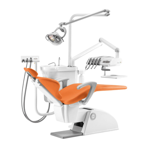
The instruments table of Duke Easy can accommodate two tools, a syringe and a suction cannula.
The tools are hanging tubes.
Attaching the arm at the base of the dental chair allows a rotation of the table around the patient allowing
use at right and left-handed operators at the same time with a single device.
Ability to install a table tray on a double pantografic arm.
High-speed suction tubes and their connections are easily removable for disinfection treatment. The
filter easily and hygienically clean.
Duke Easy is combinable with the Directive 93/42 Moon dental chair/CE and O.M.S. s manufactured by.
CE 0051 refers only to Duke Easy.

DUKE EASY S.T.01/3AW Rev.0 01/2017
6
SAFETY
Warning symbol
WARNING: Indicates a hazardous situation that can lead to property damage or mild to moderate injury.
DANGER: Indicates a hazardous situation that may result in serious injury or death
Rules
-DANGER: to prevent the risk of electrical shocks, the equipment must be connected exclusively to
power lines provided with a grounding system according to the law in force in your country.
-DANGER: Before powering the equipment after installation, a repair or technical service, check and,
if necessary, hook up the connection of the grounding cables to the screw identified by the grounding
system symbol.
-DANGER: The device must be installed in rooms featuring electrical systems that are up to local code.
-DANGER: The installation of the dental unit has to be done by an OMS authorized technician; the
choice of the pipelines is up to the designer of the electrical system and they have to be placed by a
qualified technician according to the law in force in the country.
-DANGER: Never allow the device to be used by non-professional operators or anybody who has not
read the instruction manual.
-Always check that the device is in good condition.
-WARNING: Do not use the device if any part of it is defective or worn. If this is the case, call in
authorized O.M.S. technical personnel.
-WARNING: Have defective or worn parts replaced with original, warranted O.M.S. spare parts only.
-DANGER: Do not operate the equipment on patients with pacemakers.
-DANGER: Device not suitable for use in rooms where use is made of a flammable anaesthetic mixture
with air or with oxygen or with nitrous oxide.
-WARNING: Do not use the device when there is liquid on the floor.
-WARNING: Tips and dental drills for micromotors, tooth scalers and turbines are not included in
O.M.S. supply. We recommend using parts conforming to the standard ISO 10993 that have to be
cleaned and sterilised according to the methods defined by their manufacturers.
-DANGER: Do not make changes to this device without the manufacturer’s permission. The use of
unapproved accessories and/or unauthorised changes can cause imminent personal injury hazards as
well ad material damages.
-WARNING: All maintenance work must be carried out with the device switched off and with no patient
in the chair.
-DANGER: some parts, identified by the symbol “WARNING – LIVE PARTS”
, are energised with mains voltage even after switching off the power
switch. If these parts require service, cut out voltage to the system supplying power to the equipment,
before making any operations.
-DANGER: the power switch isolates the equipment from the mains electricity. So, before performing
any operations in the equipment, make sure that the power switch is off.

DUKE EASY S.T.01/3AW Rev.0 01/2017
7
-WARNING: For special operations that require chair movements to be locked, make sure to enable
the specific function (see par. LOCKING CHAIR MOVEMENTS).
-WARNING: The instructions found in this manual and in the wiring diagram must be followed to
connect a suction unit; the suction unit must have EC markings as per directive 93/42/EEC as amended
“Medical Equipment” and meet international safety regulations IEC EN 60601-1 (Medical electrical
equipment –General safety regulations), IEC EN 60601-1-2 (Medical electrical equipment –Collateral
standard: Electromagnetic compatibility).
-DANGER: when moving the chair, both in manual and especially in automatic mode, do not place hands
and feet near the bottom of the chair to avoid crushing hazards
-WARNING: during automatic chair movement, the operator must stand near the dental unit.
-WARNING: When moving the instrument table, assistant table and operating lamp, be careful of the
patient and personnel in the surgery to avoid injuring or crushing the patient or personnel in the
surgery.
-WARNING: Never sit on the tip or foot of the chair.
-WARNING: During instrument table movement, patients and personnel in the surgery could be injured
by sharp instrument tips.
-WARNING: before putting equipment into operation after periods of disuse, accurately disinfect the
air and water supply lines, clean and drain the lines and then proceed with disinfection.
-WARNING: In the event of prolonged dental work on senior citizens, be careful of the formation of
bedsores.
-WARNING: When moving the chair and, especially, the head rest, the patient’s hair could become
entangled.
-WARNING: The equipment is equipped with a general water tap. During use, the tap should be open.
At the end of the work day, the tap should be closed or, alternatively, close the unit’s general supply
tap in the surgery.
DEFINITION OF INTENDED USE
Dental unit intended to treat dental pathologies, intended for professional operator use (dentists).
ADMITTED ENVIRONMENTAL CONDITIONS
ADMITTED ENVIRONMENTAL CONDITIONS FOR TRANSPORTATION AND
STORAGE
The packaged device can be exposed for a period of no more than 15 weeks to the following environmental
conditions:
Temperature range -40 to +70°C
Relative humidity range: 10 to 100% non condensing
Atmospheric pressure from 500 to 1060 hPa

DUKE EASY S.T.01/3AW Rev.0 01/2017
8
ADMITTED ENVIRONMENTAL CONDITIONS FOR OPERATION
Temperature range +10 to +40°C
Relative humidity from 30 to 75%
Atmospheric pressure from 800 to 1060 hPa
Nominal operating altitude ≤ 3000m
Pollution degree 2
Overvoltage category II
WARRANTY
The product is covered by a warranty period of 36 (thirty six) months from the date of installation from
the purchaser. The warranty conditions are shown inside the warranty booklet supplied with the device.
The guarantee applies to the purchaser and to the product specified in the installation and testing report
and covers all mechanical and electrical interventions relating to the product concerned.
The guarantee will be valid after the ordering party will be compiled and sent to O.M.S. spa of installation
and testing. Essential condition to access the warranty is return to O.M.S. spa of installation and testing,
in the original by fax or by certified mail within ten days of installation, under penalty of forfeiture of
the guarantee.
O.M.S. SPA Officine Meccaniche Specializzate
Via Dante 20/A 35030 Caselle di Selvazzano (PD) Italia

DUKE EASY S.T.01/3AW Rev.0 01/2017
9
2. TECHNICAL SPECIFICATIONS
Model DUKE EASY
Manufactured by O.M.S. S.p.A. Officine Meccaniche Specializzate
Via Dante 20/A - 35030 Selvazzano Dentro Padova Italia
Class I
Applied parts Type B
Equipment protection level IPX0
Foot control protection level IPX1
ELECTRICITY SUPPLY
Rated voltage 230 Vac +/-10%
Rated frequency 50/60 Hz
Connection to the mains with cables that comply with current code in the given area of use.
Rated current 4A
Rated power 900 W
HYDRO-PNEUMATIC SUPPLIES
Pneumatic supply from 450 kPa to 650 kPa (from 4.5 to 6.5 bar)
(consumption of aspirated air equalling approx. 40 litres/minute)
Water supply from 200 kPa to 400 kPa (from 2 to 4 bar)
(consumption of water equalling approx. 2 litres/minute)
Max. temperature 30 °C
OPERATING PERIODS
Chair intermittent 1' on / 10' off
Syringe 6F (hot water) intermittent 5' on / 10' off
Polymerization lamp intermittent 20’ on / 3’ off
Tooth scaler (with water) intermittent 3' on / 5' off
Micromotor intermittent 3' on / 3' off
Operating lamp continuous
Syringe 3F (cold water) continuous
EDI OPERATING LAMP (with cooling fan)
Halogen lamp: 17 Vac, 95 W
Colour temperature: 5,000 °K
Focal distance:700 mm
Operating field (at 700 mm): 60x180 mm
Max. luminous intensity (at 700 mm): 25000 Lux.
ALYA SPOT LIGHT (led)
Colour temperature: 5,000 °K
Focal distance:700 mm
Operating field (at 700 mm): 170x85 mm
Max. luminous intensity (at 700 mm): 8000-50000 Lux.
Cri (colour rendering index) >85
MAIA SPOT LIGHT (led)
Colour temperature: 5,000 °K
Focal distance:700 mm
Operating field (at 700 mm): 170x85 mm

DUKE EASY S.T.01/3AW Rev.0 01/2017
10
Max. luminous intensity (at 700 mm): 3000-35000 Lux.
GCOMM POLARIS OPERATING LAMP (led)
Colour temperature: 4200-6000 °K
Focal distance:700 mm
Operating field (at 700 mm): 70x140 mm
Luminous intensity: 15000-30000 Lux.
MISCELLANEOUS
Weight circa 165 Kg
Maximum load allowed on chair 135 Kg
Length of foot control cable 2.5 m
Minimum space recommended for device installation approximately 3.20x3.00x3.00 m (LxHxD)

DUKE EASY S.T.01/3AW Rev.0 01/2017
11
IMPORTANT NOTE
The devices, in the models foreseen and indicated in this document, are designed and built in compliance
with directive 93/42/EEC "Medical Devices" (as amended) and international safety standards IEC EN
60601-1 (Medical Electrical Equipment - General Requirements for Safety), IEC EN 60601-1-2 (Medical
Electrical Equipment - Collateral standard: Electromagnetic Compatibility), IEC 80601-2-60 (Medical
electrical equipment: Particular requirements for basic safety and essential performance of dental
equipment), ISO 6875:2011 (dental chairs), ISO 7494-1:2011 (dental units)
, UNI CEI EN ISO 14971:2009 (risk analysis), CEI EN 62304:2006 (ing. Software), CEI EN 62366:2008
(ing. Usability), CEI EN 60601-1-6:2011 (usability).
O.M.S. declines any and all responsibility for equipment safety and reliability in the following cases: if
installation, additions, re-calibration, modifications or changes are not performed by O.M.S. authorised
technicians following the instructions and using the components supplied by O.M.S. exclusively; if the
electric system installed in the workplace does not comply with IEC standards; and/or if the equipment
is not used according to the operating instructions.
NAMEPLATE DATA
An identification plate is affixed to the equipment indicating general device data.
A. Device model
B. Rated voltage and nature of current (alternating )
C. Rated frequency
D. Rated current
E. Rated power
F. Device serial n°
G. Manufacturer
H. Cooling fluid temperature
I. WEEE symbol
J. Applied part Type B
K. Certification markings: Medical device directive 93/42/EEC and subsequent amendments
L. Mandatory, see enclosed documentation
M. Follow operating instructions
3. TECHNICAL INSTRUCTIONS FOR INSTALLATION
PACKAGING
The unit is shipped in a box containing instructions accessory box, S.T. 01/3, lamp *, arm lamp *, * suction,
fixing screws. (*)Present only in case of a specific request at the order.

DUKE EASY S.T.01/3AW Rev.0 01/2017
12
Outside each box there is a flag that indicates the order confirmation numbera and the model.
Note: the packaging of an eventual seat O.M.S. is separated.
ASSEMBLY
1. Remove the equipment from its packaging;
2. Place the chair on the previously made settings using the installation plan and adjust any “play” by
tightening or unscrewing the adjustment feet as necessary, secure the chair to the floor using the
two supplied dowels;
3. If an operating mounting lamp and electrical connection;
4. verify (and possibly perform) ground cables to the screw marked with the ground symbol;
5. to connect the vacuum pump (see the wiring diagram) in the same manner as described in the next
bullet for power cables (securing leads and traction).
6. remove the cover at the base of the dental chair, unscrewing the screws D
to maintain water and air connections (see section
developed), aspiration, exhaust and finally the power grid (Terminal); the power cables on the terminal
board must be general, with nylon ties, insulating specially drilled and placed under the Terminal, in
particular it must be ensured that, in the event of failure of the fasteners (clamps), the protective
conductor is not subject to traction as long as network cables are still connected to terminal
3. Fit the accessories (instruments), if any, on the instrument and dental assistant tables.
N.B.: Refer to the wiring and installation diagrams provided for all electrical connections.

DUKE EASY S.T.01/3AW Rev.0 01/2017
13
CONNECTIONS
First, make sure that the flow of air and water from the water and pneumatic mains is regular. O.M.S.
declines any and all responsibility for faults or damage originating from non-compliance with the warning
below:
Water supply:
Water with medium/low salt content (fit a water softening device if necessary), to be connected to the
6x8 diameter tube (see paragraph TECHNICAL SPECIFICATIONS for admitted pressure).
Pneumatic supply:
Compressed air, preferably dehumidified and oil-suspension free, to be connected to the 4x6 diameter
tube (see paragraph TECHNICAL SPECIFICATIONS for admitted pressure).
We recommend making a temporary direct connection between the water delivery pipe and the drain pipe,
and letting the water circulate for a few seconds before installing the equipment. This enables elimination
of any impurities from the tubes.
TESTING AND PUTTING INTO OPERATION
IMPORTANT WARNING
During testing, check the mechanical stability of the equipment after placing all the mobile elements and
accessories (table, lamp, etc.) in the most unsuitable position possible.
1. Ensure that the instrument table is perfectly level: if an unusual tilting is identified, adjust the table
using the screw (detail A in Figure) located inside the front part of the arm.
2. Check the manual pantograph base and backrest up and down controls, and the automatic return to
exit, rinse position and return to last position control to ensure they are working properly. Check and
store correct positioning of the programs (see sections MANUAL CONTROLS and AUTOMATIC
CONTROLS).
3. Check that limit switches and safety systems are working properly (see section SAFETY SYSTEMS).
4. Check correct calibration of the pressure regulators and general flow regulators and that of each
instrument. These devices have already been calibrated by O.M.S. in the workshop, but they may
require an inspection or re-calibration.

DUKE EASY S.T.01/3AW Rev.0 01/2017
14
Note: The equipment is equipped with a general water tap. During use, the tap should be open. At the
end of the work day, the tap should be closed or, alternatively, close the unit’s general supply tap in the
surgery.
DANGER: Before performing any operations in the equipment, always make sure that the power switch is
off..

DUKE EASY S.T.01/3AW Rev.0 01/2017
15
4. CONTROLS - ADJUSTMENTS - INDICATORS
SAFETY SYSTEMS
The dental chair is supplied with safety devices which minimise the risk of crushing or collision with
underlying objects during chair descent. Safety devices include a special sensor on the dental chair back
and an electromechanical safety device installed at the base of the dental chair back.
Whenever the sensor installed on the dental chair back is engaged during a descent movement (either of
the pantographic arm or chair back), the part moving down stops. A warning LED at the bottom of the
seat (detail B) goes ON and stays ON until the obstacle causing safety device engagement is cleared. To
perform the required movement, remove the obstacle and repeat the control.
The sensor installed on the back of the dental chair is calibrated as instructed below.
-Place the chair in the permanent position;
-Put a screwdriver in the hole for the calibration of the sensor located at the bottom of the chair seat
(detail B). Turn the screwdriver clockwise to reduce the sensor sensitivity and anticlockwise to
increase it.
-Control the pantographic arm or chair back to move downwards and touch the back of the dental chair
to engage the safety sensor (detail A) in order to check its sensitivity. Repeat the operations from
the previous item until the ideal sensor sensitivity is found.
When the back safety sensor is engaged, all downward movements of both the back and pantographic arm
are disabled.
The back of the dental chair is also provided with an electric and mechanical safety device which stops
the descent movements of both the pantographic arm and back whenever obstacles are present in the
outreach of the keyboard. Whenever this safety device is engaged, all downward movements of both the
pantographic arm and back are disabled.
During automatic movements of the dental chair (position reset, memorised positions or rinsing positions),
press any control of the dental chair (on the pushbutton panels of the dental unit or foot control) to
immediately stop the dental chair.
Dental chair movement may be disabled both at equipment switch on and during normal operation, if one
or more than one safety system is active.

DUKE EASY S.T.01/3AW Rev.0 01/2017
16
INSTRUMENT TABLE
The instrument table offers two tools, a syringe and a suction cannula.
Comprises the Group of solenoid instruments with clearly visible, all its adjusters. The functions of each
device are described in the chapters to the forms tool. Regulations that are not equipped with knob must
be takend off by authorised technicians O.M. S
PULSANTIERA
The controls are entirely under sealed membrane, this enables greater reliability, eliminating crevices
and the disinfection of the surface.
The key functions are:
Reversing command of the micromotor with warning led
(with led off the direction of rotation is normal)
command of spray preselection and fiber optics
(press button for 3 seconds), with preselected led fibre optic lighting
and with preselected spray active led.
The other buttons are inactive.
TURBINE MODULE
Turbine operation is achieved by lifting the instrument from its position, moving it to the surgical field,
and then press the foot pedal (see operation section).
Lifting the instrument by the table are inhibited all other dynamic tools and all the movements of the
dental chair.

DUKE EASY S.T.01/3AW Rev.0 01/2017
17
The spray is always preselected. To adjust the water to spray one acts on the faucet in place behind the
Chair. By turning the tap clockwise you get a gradual decrease of water flow to the spray until its complete
exclusion, the opposite rotating in the opposite direction. It is recommended not to intervene in other
regulations placed at the side of the spray faucet.
If the instrument is equipped with optical fibres lighting system, these are switched on by pressing the
control command pad spot Tablet (when the function is on, it affects all instruments). The
activation of the function is displayed by the lit led (D).
Air pressure Recommended (measured during operation of the turbine) is set at the time of testing in
the O.M.S.. Calibration must be re-evaluated at the time of installation of the appliance using a
manometer, respecting the pressure values indicated by the manufacturer of the turbine. This must be
done by an authorised O.M.S..
For more details see the attached manufacturer's instructions.
ELECTRIC MICROMOTOR MODULE
The function of the micromotor is achieved by lifting the instrument from its place, moving it to the
surgical field and then pressing the foot pedal (see operation section MICROMOTOR).
Lifting the instrument from the table are inhibited all other dynamic tools and all the movements of the
dental chair.
The micromotor allows you to work with a variable speed from a minimum of about 900 RPM to a maximum
of 40,000 rpm
Normally the micromotor will have a clockwise direction rotation. For reversal of direction of rotation,
after lifting the tool, activate the reverse command in the instruments table.
It is recommended that the change of direction of rotation is made only when the motor is stopped, to
prevent damage.
The spray is preset by typing the command ; the activation of the function by the lit led is
displayed. See also section OPERATION micromotor.
To adjust the water to spray one acts on the faucet in place behind the Chair. By turning the tap clockwise
you get a gradual decrease of water flow to the spray until its complete exclusion, the opposite rotating
in the opposite direction. It is recommended not to intervene in other regulations placed at the side of
the spray faucet.

DUKE EASY S.T.01/3AW Rev.0 01/2017
18
If the instrument is equipped with optical fibres lighting system, these are switched on by pressing
The command , place on command pad table (when the function is on, it affects all instruments).
The activation of the function is displayed by the lit led (D).
SCALER MODULE
Generator operation is achieved by lifting the instrument from its place, moving it to the surgical field
and then pressing the foot controller lever (see operation section GENERATOR).
Lifting the instrument by the table are inhibited all other dynamic tools and all the movements of the
dental chair.
To adjust the water to spray one acts on the faucet in place behind the dental chair. By turning the tap
clockwise you get a gradual decrease of water flow to the spray until its complete exclusion, the opposite
rotating in the opposite direction. It is recommended not to intervene in other regulations placed at the
side of the spray faucet.
If the instrument is equipped with optical fibres lighting system, these are switched on by pressing
the command , placed on the command pad of the table (when the function is on, it affects all
instruments). The activation of the function is displayed by the lit led (D).
For more details see the attached manufacturer's instructions.
For the scaler SATELEC NEWTRON SP power regulation must be done according to the tip on the
handpiece.
SYRINGE MODULE
The syringe operates at any time by simply pressing one of the two levers enabling either water or air
supply (left-hand lever for water and right-hand lever for air). When these two supply buttons are
pressed simultaneously, spray water is delivered.
For further details refer to the manufacturer’s operating instructions enclosed.

DUKE EASY S.T.01/3AW Rev.0 01/2017
19
FOOT CONTROL
The equipment foot control was designed to control all the possible functions of the instruments with a
simple movement of the lever (A).
N.B.: when the instrument is extracted, it is automatically connected to the foot control, thus disabling
all the other instruments even at a subsequent extraction (by the dental assistant, for instance).
TURBINE OPERATIONS
Extract the instrument from its housing (this operation is shown on the display). Then:
- pressing the lever (A) of the foot control in the rest position will enable the chip-blower;
- move the lever A to the right to operate the instrument. If lever A is pressed simultaneously, the
turbine is sprayed (standard configuration). Upon request, at the time of installation, the technician can
change the connections so that the spray function can be operated without having to press the lever.
MICROMOTOR OPERATIONS
Extract the instrument from its housing (this operation is shown on the display). Then:
- pressing the lever (A) of the foot control in the rest position will enable the chip-blower;
- move the lever A to the right to operate the instrument. The spray is pre-selected in the instrument
table by engaging the control ; Then, spray delivery is possible when the foot control lever (A) is
slightly pressed with the instrument in operation (standard configuration). Upon request, at the time of
installation, the technician can change the connections so that the spray function can be operated without
having to press the lever.
To invert the micromotor rotation, move the foot control lever A to the left and press it downwards. This
operation is viewed on the display, and an on-off beep accompanies this function, which is disengaged by
moving the lever (A) to the left again and pressing it downwards.
SCALER OPERATIONS

DUKE EASY S.T.01/3AW Rev.0 01/2017
20
After removing the instrument from its place by moving the lever (A) to the right to activate the tool.
The spray you pre-select in instruments table by typing the command ;then you can have the
spray dispensing by pressing the lever rheostat (A) if the instrument is in function (standard
configuration). Upon request, at the time of installation, the technician can change the connections so
that the spray designed to be dispensed without the need to depress the lever.
CHAIR CONTROLS FROM THE FOOT CONTROL
The foot control is equipped with two side levers (see det. B and C) that are operated to position the
dental chair using foot controls:
-moving the lever (B) up will raise the seat;
-moving the lever (B) down will lower the seat;
-moving the lever (C) up will lower the backrest;
-moving the lever (C) down will raise the backrest.
OTHER ACCESSORIES
For accessories not previously described buy indicated in the product description, see the specific user
manuals supplied with the equipment.
GROUND BOX
In the box to the floor are housed all electrical control systems, pneumatic and water together.
Inside, it is possible to carry out the connection of the appliance to the mains, the mains water supply,
drainage, compressed air and the flue pipe from the engine of the surgical suction, if any.
Access is by unscrewing the screws D and remove plastic cover C with the caveat of disconnect power
before opening (as described in the section on SAFETY).
Table of contents
Other OMS Dental Equipment manuals
Popular Dental Equipment manuals by other brands

NSK
NSK S-Max M65 Operation manual
Aseptico
Aseptico ALU-40TC Operation and maintenance instruction manual

dentalfarm
dentalfarm MICRA Evoluzione User and maintenance manual
DENTSPLY
DENTSPLY thermaprep 2 Directions for use
Zhermack
Zhermack hurrimix 2 user manual

Dabi Atlante
Dabi Atlante Bellagio owner's manual

