On Board ProTech-C 4815 Installation and operating instructions

Factory Service Center
200 International Drive STE 195
Portsmouth, NH 03801
Hours of Operations: 8:30 AM - 5:00 PM Eastern Time
Tel: 603-373-6500
Fax: 603-433-4442
e-mail: [email protected]
www.onboardsolutions.biz
IMPORTANT NOTICE
This manual contains important safety and operating instructions for ProTech-C model 4815.
Please save and read all safety, operating, and installation instructions before installing or applying
AC power to your ProTech-C series battery charger.
02/09 Rev 48V
specifications subject to change without notice
Pro
Tech
-C
Industrial Battery Charger
Models Part No. DC Amperage No. of Outputs Volts DC
ProTech-C 4815 90435 15 Amps 1 48
Product Manual and Installation Guide
Advanced Electronic, Fully Automatic, 3-Stage On-Board
Industrial Style Battery Charger.
Designed and Constructed to:
UL 1564 3rd Ed.
c UL To: CSA C22.2 No. 107.2-01
FCC Class B
On Board
Solutions
A ProMariner Company
On Board
Solutions
A ProMariner Company
TWO YEAR
LIMITED
WARRANTY

14
Frequently Asked Questions
Q: Do I have GEL Cell batteries?
A: AGM and GEL Batteries are often confused. The best way to determine is to look
at the battery housing and see if it is identified as a GEL battery. If you don’t know
contact the manufacturer of the battery.
Q: How do I know what profile to set my charger to based on my battery type
(i.e. manufacturer and battery technology)?
A: This manual includes some general recommendations but if you don't see
your type listed, then please check the www.onboardsolutions.biz website
under the "Support" section or call our technical support group for advice on
the best setting to choose.
Q: LEDs will not illuminate?
A: Check to make sure that an AC power connection is made. If LED's remain off,
please proceed to the test procedure on Page 12.
Q: LED's are ON but the Pro Tech C is not Charging?
A: Check Reverse Polarity Fuse, located directly under the DC End Cap. Replace
as needed and re-test unit to the procedure on page 12.
Q: Will water damage my charger?
A: Yes, these are dry mount chargers and are intended to be mounted in a dry
location. The ProTech-C 2 year limited warranty does not provide coverage for
damage caused by water.
Q: Do the chargers really need ventilation?
A: Ideally, the charger should be ventilated in order to maintain proper cooling.
Consult the factory if you are unsure of the mounting location.
Q: The ProTech-C Series charger is getting hot. What should I do?
A: The charger may get to the point where it can be touched, but, is quite warm.
This is normal. Note: the charger is thermally protected and in the event of over
temperature the ProTech-C will shut down and the "Over Temp" LED will illuminate.
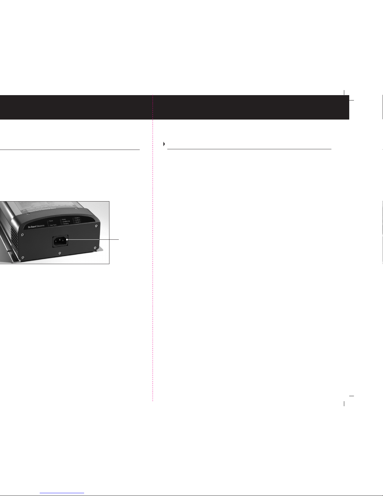
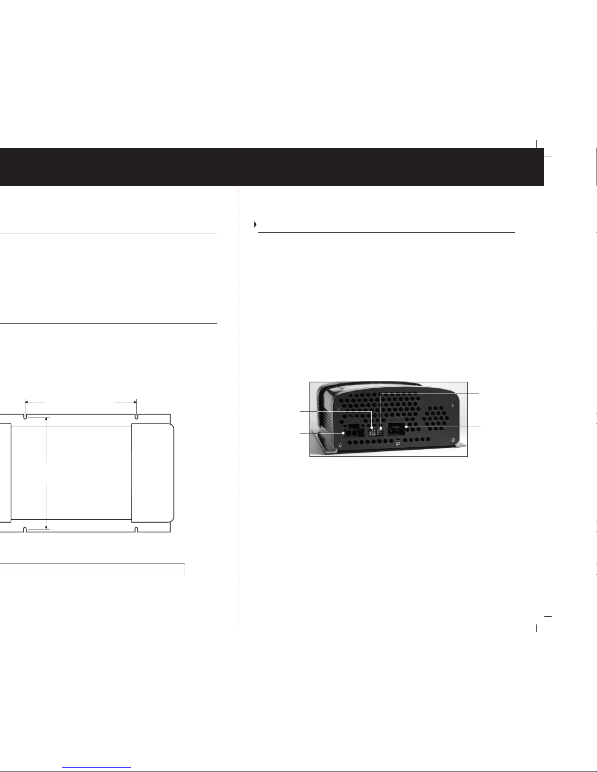
Q: What are the AC Input voltage requirements, and how can I change the voltage
from 120v to 240v?
A: The ProTech-C charger is equipped with Universal / Wide Range AC input
technology and will automatically adjust for the correct voltage.
Frequently Asked Questions
Table of Contents
CAUTIONS, WARNINGS AND SAFETY INSTRUCTIONS… 2-4
Setup and Operation… 5-8
Selecting a Charging Profile and Understanding Battery Types… 7-9
Pre-installation, Installation... 9-11
Installation Continued, DC Connections & Wiring Diagrams… 10-11
Installation Continued, AC Connections... 11
Troubleshooting... 12
Periodic Maintenance... 13
Frequently Asked Questions... 14
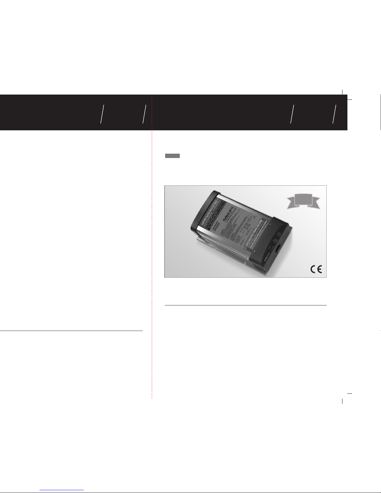
The ProTech-C Series battery charger incorporates industry leading technology, delivering
fully automatic and Sequential Multi-Stage Charging, conditioning and maintenance of all
batteries connected.
High Line Features:
Automatic Wide Range / Global AC input 95 - 250 VAC
Single Output Charging, Conditioning and Maintenance of batteries while
extending battery life.
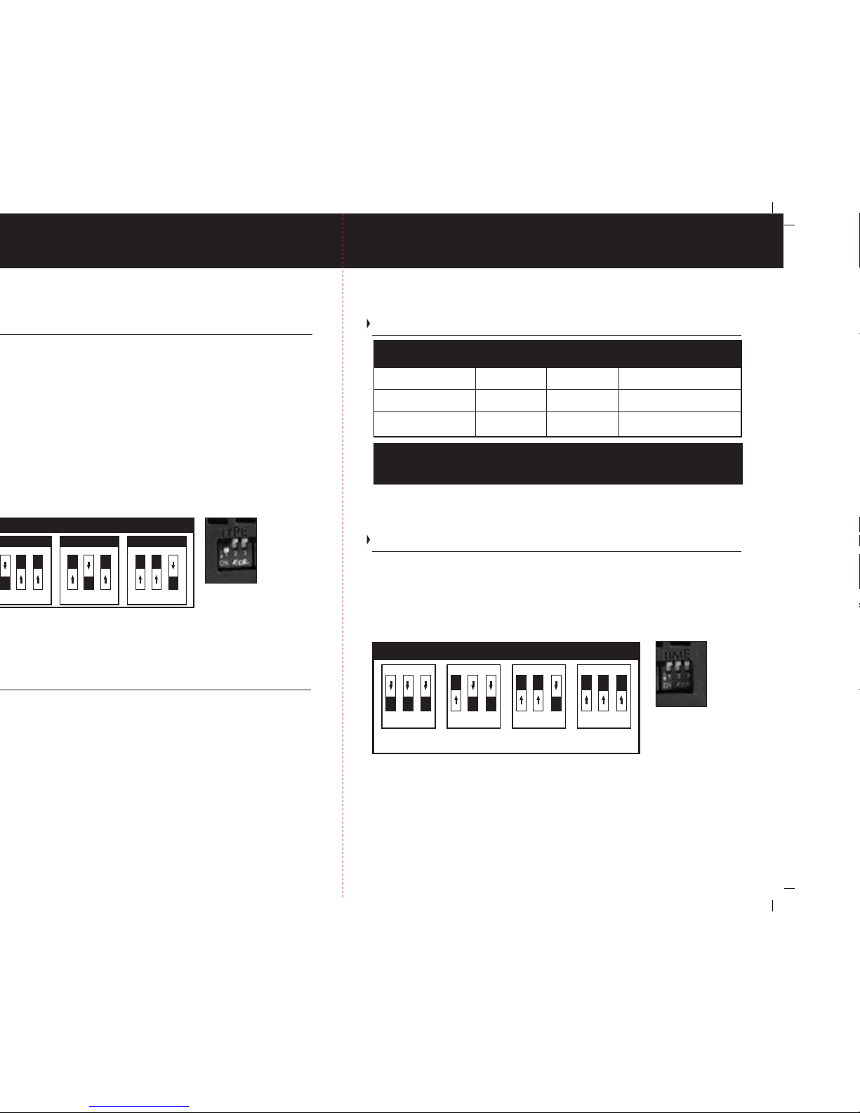
User Selectable Absorption / Conditioning Mode: 2, 3, 4 or 6 hours.
User Selectable Battery Type / Charging Profile Selector - 3 Settings:
Out ofBox Factory/User Setting 1:Flooded (Lead-Acid) :
Factory default setting This profile is recommended
for Lead Acid batteries by Trojan, Crown, Discover and Exide amongst others.
User Setting 2: This profile is recommended for Lead Acid batteries by US Battery and Interstate amongst others.
User Setting 3: This profile is typically recommended for AGM batteries.
Note: See Page 8 for DC Voltages of each setting referenced above.
Consult the factory if you are unsure how to set your charger for your battery type as incorrect
settings can reduce the life of your batteries due to improper charging.
Standard Features Include:
Advanced Electronic Technology yielding a heavy duty and compact design.
Expanded LED Operation Status Center Includes High Visibility LED’s for: Charging, Conditioning
and Ready. Discreet Battery Type LED indicators for: Flooded, AGM and GEL Batteries.
Fully Automatic Multi-Stage Charging (example below is for Profile 1.
Factory set out of the box for Flooded (lead-acid) battery (s).
Multi-Stage Battery Charging (Lead Acid Flooded Battery)
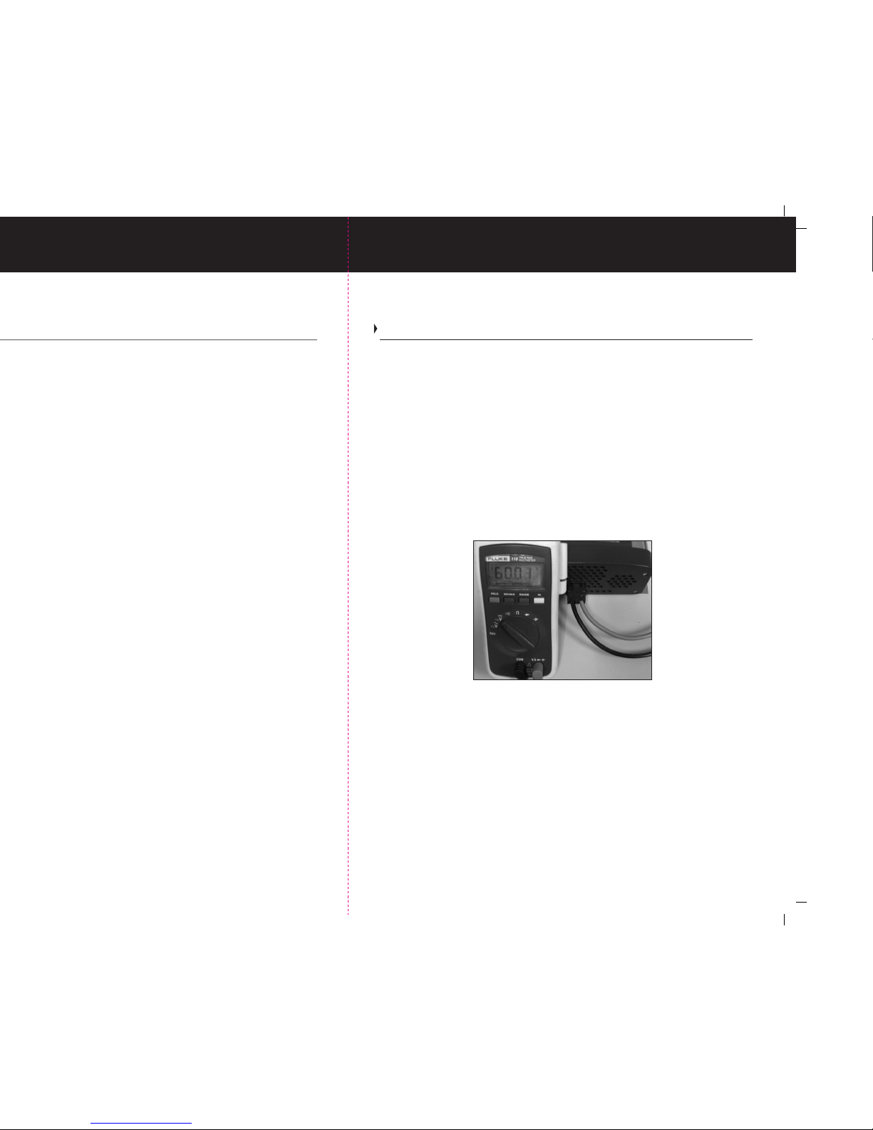
Stage 1 Fast Charge/ Charging = Maximum Amperage Output until Battery (s) reach 60.0 VDC.
Stage 2 Absorption Charge / Conditioning Mode = Precision 60.0 VDC to Fully Charge
& Desulfate Battery (s).
Stage 3 Float / Maintenance/ Ready Mode = Precision Finishing & maintenance Voltage of 54.0.
1
Designed and Constructed to:
UL 1564, ULc, CE, FCC Class B

2
Cautions, Warnings & Safety Instructions
Important Safety Instructions
WARNING: HIGH VOLTAGE / ATTENTION : HAUTE TENSION
AVOID SERIOUS INJURY OR DEATH FROM ELECTRICAL SHOCK. BEFORE OPENING TURN OFF AC SUPPLY POWER.
CHOC ELECTRIQUES PEUVENT PROVOQUER LA MORT OU DE SERIEUSE BLESSURES. AVANT D'OUVRIR LA BOITE,
COUPER LE COURANT.
CAUTION:
- HOT SURFACES - TO REDUCE THE RISK OF BURNS, DO NOT TOUCH.
- CHARGE ONLY USER SELECTABLE TYPE BATTERIES (FLOODED, AGM, OR GEL) OTHER TYPES OF BATTERIES
MAY BURST CAUSING PERSONAL INJURY AND DAMAGE
- RISK OF ELECTRIC SHOCK. NO USER SERVICEABLE PARTS. RETURN TO MANUFACTURER FOR SERVICING
- THIS CHARGER IS MEANT FOR CONTINUOUS DUTY
ATTENTION :
- SURFACES CHAUDE-NE PAS TOUCHER, RISQUES DE BRULURES
- UTILISER POUR ATTENTION: CHARGER UNIQUEMENT LES BATTERIES DU TYPE (PLOMB/ACIDE OU PLOMB/GEL/AGM).
D’AUTRES TYPES DE BATTERIES POURRAIENT ÉCLATER ET CAUSER DES
BLESSURES OU DOMMAGES
- RISQUE DE CHOCS ELECTRIQUE-RETOURNER AU FABRIQUANT POUR SERVICE.
- CE CHARGEUR EST FABRIQUE POUR LE DEVOIR CONTINU
WARNING: LOW VOLTAGE / ATTENTION : BASSE TENSION
ELECTRICAL BURN AND SPARK HAZARD. BEFORE OPENING DISCONNECT CHARGER CONNECTIONS AT BATTERY(S).
(DANGER DE BRULURES ELECTRIQUE ET ETINCELLES). AVANT D'OUVRIR LA BOITE DECONNECTER LES
CONNECTIONS ENTRE CHARGEUR ET BATTERIE.
Before connecting to batteries or AC power, read all instructions and cautionary markings
on the battery charger and batteries. Do not discard this manual, save it for future reference.
1. SAVE THESE INSTRUCTIONS / CONSERVER CES INSTRUCTIONS. CE MANUEL
CONTIENT DES INSTRUCTIONS - This manual contains important safety and operating
instructions for all ProTech-C battery chargers.
2. Do not expose charger to rain or snow.
3. Use of attachments not recommended or sold by On Board Solutions will void warranty
and may result in a risk of fire, electrical shock or personal injury.
4. Do not operate the charger if it has received a sharp blow, direct hit of force, been
dropped or otherwise damaged in any way; take it to a qualified serviceman.
5. Do not disassemble the battery charger. If service or repair is required contact your local
dealer. Incorrect reassembly may result in a risk of electric shock or fire.
6. To reduce the risk of electrical shock, remove 120 volt or 240 volt AC power. Also remove
DC battery connections prior to any maintenance or cleaning. Turning off controls will not
reduce this risk.
WARNING AVOID SERIOUS INJURY OR DEATH FROM FIRE, EXPLOSION OR ELECTRICAL SHOCK
- Make connection in an open atmosphere free of explosive fumes.
WARNING: HIGH VOLTAGE / ATTENTION : HAUTE TENSION
AVOID SERIOUS INJURY OR DEATH FROM ELECTRICAL SHOCK. BEFORE OPENING TURN OFF AC SUPPLY POWER.
CHOC ELECTRIQUES PEUVENT PROVOQUER LA MORT OU DE SERIEUSE BLESSURES. AVANT D'OUVRIR LA BOITE,
COUPER LE COURANT.
WARNING / AVERTISSEMENT :
DO NOT EXPOSE TO RAIN OR SPRAY / NE PAS EXPOSER AUX INTEMPÉRIES
13
Periodic Maintenance
Process:
When:
For Flooded (Wet) batteries, follow the manufacturers’ instructions
to monitor and maintain proper levels of distilled water. (not tap
or bottled water that contains minerals) in each battery
Monthly
Periodic Maintenance
Process:
When:
Visually inspect all wiring for cuts and abrasions. Contact On
Board Solutions if charger needs to be serviced.
Monthly
Process:
When:
Clean and tighten all battery connections. Follow
manufacturer's instructions for cleaning a battery. Clean all
battery terminals with a wire brush where required and tighten
all battery connections.
Monthly

3
Cautions, Warnings & Safety Instructions
Important Safety Instructions Continued
7. WARNING – RISK OF EXPLOSIVE GASES.
a) WORKING IN THE VICINITY OF A LEAD-ACID BATTERY IS DANGEROUS. BATTERIES
GENERATE EXPLOSIVE GASES DURING NORMAL BATTERY OPERATION. FOR THIS
REASON, IT IS OF UTMOST IMPORTANCE THAT EACH TIME BEFORE USING YOUR
CHARGER, YOU READ THIS MANUAL AND FOLLOW THE INSTRUCTIONS EXACTLY.
b) To reduce risk of battery explosion, follow these instructions and those published by
battery manufacturer and manufacturer of any equipment you intend to use in vicinity of
a battery. Review cautionary markings on these products.
8. PERSONAL PRECAUTIONS
a) Someone should be within the range of your voice or close enough to come to your
aid when working near a lead-acid battery.
b) Have plenty of soap and water nearby in case battery acid comes in contact with skin,
clothes or eyes.
c) Wear complete eye protection and clothing protection. Avoid touching eyes while
working near battery(s).
d) If battery acid contacts skin or clothing, wash immediately with soap and water. If acid
enters eye, immediately flood eye with running cold water for at least 10 minutes and get
medical attention immediately.
e) NEVER smoke or allow a spark or flame in the vicinity of a battery or engine.
CAUTION - To reduce the risk of injury, charge only lead-acid type rechargeable batteries
(Flooded, Sealed Flooded, ( Lead-acid) or AGM (Absorbed Glass Mat)). Other types of
batteries may burst, causing personal injury. The ProTech-C is factory set for Flooded
(Lead-acid) batteries.
Check the position of the battery type selector switch before
applying power to insure the charger is in the correct setting for the battery type. This
switch is located on the DC end of the charger. see Page 7.
Incorrect assembly may result in electrical shock or fire.
f) Be extra cautious to reduce risk of dropping a metal tool onto a battery, it might spark
or short-circuit the battery or other electrical part that may cause explosion
g) Remove all personal metal items such as rings, bracelets, necklaces, watches, and
jewelry when working near a battery. A battery can produce a short circuit current high
enough to weld a ring or any other metal, causing serious burns.
h) Do not use the battery charger to charge dry cell batteries that are commonly used
with home appliances i.e. a cordless power drill battery. These batteries may burst and
cause injury to persons and damage to property.
i) NEVER charge a frozen battery.
12
Trouble Shooting
Note: When working with tools near electricity serious electrical shock can occur resulting in injury.
1) Turn off all power to the charger and disconnect all the DC cables making sure that
no cables are in contact with equipment, other wiring, or one another.
2) Please note switch positions before changing settings. Set the user programmable
battery type selector switch to the Flooded (Lead-acid) position shown on page 7 (Note
switch position to reset after troubleshooting is complete).
3) Set the user programmable absorption /conditioning mode timer switch to one hour
as shown on Page 8 (Note switch position to reset after troubleshooting is complete).
4) Apply AC power. The charger will be in Charging Mode, followed by the Conditioning Mode.
Note: Because the batteries will not be connected during this test the transition from Charging
to Conditioning may be so quick you will not see the change in modes. This is normal and
acceptable. Once you have confirmed your ProTech-C Series Charger is in the Conditioning
mode use a digital volt meter (DVM) to check the output voltage of the charger.
5) If the voltage is 60.0V with Profile 1 selected, keep the charger AC power on with the
DC outputs disconnected from the battery(s). Leave the charger on for approximately
two hours, (make sure conditioning mode switch is set for two hours setting otherwise
it could take up to 4 hours if set in the 4 hour conditioning mode) or until ready LED is
observed. The voltage should drop to 54.0 VDC indicating Ready mode.
6) If you observe the above voltages, your charger is working correctly. Turn off the
charger and reprogram your ProTech-C charger back to your original program settings.
Apply AC power to charger.
7) If no DC Voltages are present, please disconnect AC Power and check the Reverse
Polarity Protection Fuse located under the DC output plastic end cap. If you are
reading high or lower DC voltages, please contact On Board Solutions
Customer Service 1-603-373-6500.
Trouble Shooting
ProTech-C 4815 with Profile 1 selected

4
Cautions, Warnings & Safety Instructions
Important Safety Instructions Continued
9.
PREPARING TO CHARGE
a) If necessary to replace an onboard charger from its mounted location, disconnect AC
power and remove DC charger cables at the battery to avoid possible arcing.
b) Be sure the area around the charger and batteries is well ventilated while the batteries
are being charged. Gases can be forcefully blown away using a piece of cardboard or
other nonmetallic material as a fan.
c) When cleaning battery terminals wear full eye protection to prevent corrosives from
coming in contact with eyes.
d) For Flooded (Wet) Batteries, add distilled water
(not tap or bottled water that contain
minerals)
in each cell until electrolyte reaches the levels specified by the battery
manufacturer. Do not overfill. For batteries without caps, carefully follow manufacturer's
recharging instructions.
e) Study all battery manufacturer’s specific precautions such as removing cell caps while
charging and recommended rates of charge.
f) Determine battery voltage by referring to the original equipment / operations manual
and make sure that the output voltage selector switch is set at correct voltage. If charger
has adjustable charge rate, charge battery initially at lowest rate.
1
0. CHARGER LOCATION
a) Refer to the installation section of this manual for installation of your battery charger.
b) Never place the charger directly above the battery(s) being charged; gases from battery
will corrode and damage charger.
c) Never allow battery acid to drip on the charger when reading specific gravity or filling
battery.
d) Choose a mounting location that provides adequate convection and ventilation.
e) Do not set the battery(s) on top of charger.
AC Grounding Instructions – The AC power cord includes a ground connection. Do not
remove this connection under any circumstances.
This battery charger should be installed so that it is not likely to be in contact with non
factory service personnel.
11
Installation
Applying AC Power
Apply AC power, battery type LED will turn on to indicate the battery type selected as
determined by the selector switch shown on page 7. The charging LED will illuminate
until proper voltage is achieved. Next, the Charging LED will turn off and Conditioning
LED will illuminate. The Conditioning LED will turn off after 2-6 hours depending upon
the selection of the absorption timer switch shown on page 8. After absorption mode
is complete the Ready LED will illuminate. In Ready mode your batteries are fully charged
and are being maintained at optimal battery voltage and will supply DC power for any
load up to the maximum output of the charger.
Note: for your safety the charger is equipped with an internal temperature sensor that
will shutdown the charger in the event of an overtemperature condition.
Note: your ProTech-C charger is equipped with a fan, the fan will only run when needed.
The fan is temperature controlled and will only turn on when cooling is necessary.
All Installations should be made in accordance with this manual and the certifications
pertaining to this product. Cable lengths and conductor sizes which may be desired
and are outside of those referenced in this manual must be in accordance with the
National Electrical Code and any other appropriate nationally recognized standards.
IEC AC Input
Connector

10
Installation
Input and Output Connections
The On Board Solutions ProTech-C Series Battery charger offers the simplest of
connections and is highly flexible to accommodate on-board and portable applications.
The ProTech-C employs an IEC AC input connector so no special wiring is necessary.
The output side of the unit houses the quick disconnect DC output connector and inhibit
circuit connector. Also included are the mating quick disconnect connector / cable
assemblies for connecting the ProTech-C DC output and inhibit circuit.
The ProTech-C employs a safety interlock inhibit as a standard feature with every model.
The inhibit connector has 3 output connection points associated with it. They are common
(C), normally open (N/O) and normally closed (N/C) dry contact relay points. This offers
the greatest flexibility if connected to a motor controller. The contacts will change state
from their normal condition once AC power is supplied to the battery charger. Many motor
controller units are different and have different signal requirements. The function of this
signal is to inhibit normal operation of the machine the charger is housed within when
in the charging state. Refer to the motor controller PCB (Printed Circuit Board) requirements
to determine which signal is necessary to inhibit the unit from moving when charging.
The inhibit signal can be configured for many different conditions using the common point
of the relay. The following are some examples:
Examples of Possible Inhibit Connection Methods using Normally Open or Normally Closed
Contacts. Consult with the Motor Controller provider in onboard charger applications to
determine the best method for wiring this circuit.
Note: There are many different types of inhibit operations and potentials for wiring this circuit.
Consult with the motor controller provider to determine the proper signal and connection method.
N/O
C
N/C
inhibit IN
Battery Charger Motor Controller PCB
Connected to
Battery Negative
N/O
C
N/C
inhibit IN
inhibit OUT
Battery Charger Motor Controller PCB
Setup and Operation
1) The ProTech-C Battery Charger is designed as an onboard charger. Note the connections
shown below.
2) This charger includes an IEC universal voltage input connector. It can auto-detect
any circuit rated between 95-250VAC 50 / 60 Hz.
3) The ProTech-C is designed with a Quick Disconnect DC output connector that connects
to a supplied DC output Cable assembly. While looking directly at the DC faceplate, note
that the left side of the output connector is the minus (negative) side of the output voltage
and the right side of the connector is the plus (positive) side of the output voltage. The
end cap has "NEG" and "POS" markings on it to indicate proper polarity of the output.This
cable should only be installed when AC power is removed from the charger.
4) Illustrated below are typical battery and wiring diagrams for 48 VDC applications.
5
Setup and operation
All ProTech-C Series chargers
include over current protection. To
protect DC wiring from accidental
shorts circuits and or catastrophic
failure of the DC wiring, install a
properly rated DC Fuse or DC
breaker within 7 inches of the
positive connection at the battery.
12V Battery
AC Input
DC Outputs
12V Battery
ProTech-C
48 VDC
(48 Volt DC System Voltage)
12V Battery12V Battery

6
Setup and operation
Setup and Operation
1) Install your On Board Solutions battery charger by referring to Page 9 of this manual.
2) After installation is complete including AC and DC connections please ensure proper
strain relief of all AC and DC wiring has been performed.
3) Apply AC power, you should see the following:
A.Battery Type selection LED will illuminate and iscontrolled by the battery type selector
switch. (Shown on Page 7)
B.Charging LED will illuminate until battery voltage reaches 80% battery charged threshold.
The Conditioning LED will then illuminate.
C. Conditioning LED will remain on for 2-6 hours determined by the Conditioning
timer switch.
D. After 2-6 hours the Conditioning LED will turn off and the Ready LED will illuminate
indicating that the battery(s) are fully charged and are being maintained in the float
maintenance mode and are ready for use.
E. In Ready mode the batteries are maintained at the selected battery voltage and will
supply power for loads of any type up to the maximum output of the charger.
Shown Above - Conditioning and Battery Type Selector Switches. Please refer to Pages 7
and 8 for settings and selections.
After the Fast Charge cycle, Conditioning time is determined by the Conditioning timer switch
shown in the figure above.
Full-rated current is available in Ready Mode. Voltage will normally be above charged battery
voltage at full output.
Note: The charger is equipped with an internal temperature sensor that will shutdown the
charger if internal temperature reaches unsafe levels.
Note: Your ProTech-C charger is equipped with a fan, which is temperature controlled and
will only run when cooling is necessary.
Your On Board Solutions charger is self current limiting with built in: over temperature, over
voltage, and reverse polarity protected.
Note: If you wish to manually restart (recycle) a charge sequence from the beginning, simply
disconnect and then reconnect AC power via the power cable.
9
Installation
Programmable Absorption Timer Switch Continued
Please note: Nominal measurement
Stainless steel mounting screws and hardware not included
Interlock/
Inhibit Quick
Disconnect
connector
Battery Type
Selector Switch
(Shown with
switch cover
removed)
Conditioning
Time Selector
Switch
Charger DC
Output Quick
Disconnect
connector
Installation
1) Make sure to mount the charger in a dry or weatherproof / ventilated location with
easy access. Remember to leave plenty of room for battery cables and AC wiring.
2) Six inches of clearance minimum is required on all sides to allow for adequate
ventilation for proper cooling.
3) Use the ProTech-C as a template for drilling four 1/8” pilot holes. Stainless Steel self
tapping screws (3/16 x 1-1/4” are recommended) or drill four 3/16” through holes if
using 3/16” through bolts with washers, lock washers and nuts.
THE PROTECH-C CHARGERS AUTOMATICALLY ADJUST FOR 120 VOLT OR 240 VOLT
AC INPUT POWER.
NOTE: Recommendation assumes charger is rated at 10% of battery system Amp/Hour
rating. (Example: 15 amp charger being used on 150 A/H rated system). Use the battery
20A/H system rating to determine. A 6 hour setting is available for larger system amp/hour
applications [i.e. 325 A/H] or when 10% rule is exceeded. Consult the factory if you are
unsure of what your setting should be. A 4 hour timer switch setting is typically used on 220
A/H system batteries.
4 15/16" (125mm)
6 3/16" (173mm)

7
Setup and operation
Setup and Operation Continued
Battery Type Selector Switch
All ProTech-C Series Chargers employ a user selectable battery type switch that is factory
set for flooded (Lead Acid) battery(s) [Profile 1]. Please confirm the appropriate battery type
and the orientation of selector switch before use. The ProTech-C has a switch cover to
enclose the battery type and the programmable timer switches. This should only be
opened/accessed by qualified service personnel.
In order to change the factory setting from flooded (Lead Acid) [Profile 1] to Profile 2 or 3
(see page 8 for general recommendations), simply remove AC power to the battery charger,
and locate the user programmable battery selector switch on the DC end of the charger.
Shown below you will find the three battery type configuration settings that are used to
program the 3 position dip switch as illustrated. Choose the correct setting for your battery
type.
If you are unsure of the battery type, please refer to “Selecting a Charging Profile &
Understanding Battery Types” on Page 8.
Once your ProTech-C is programmed for your battery
type apply AC power. The Battery Type LED will illuminate indicating your selection.
Note: If more than 1 battery type is illuminated, recheck you battery type selector switch
positions as illustrated above. It should be noted, only (1) of the 3 switch tabs can be in the
“ON” position for proper selection and operation.
The ProTech-C Series is equipped with a programmable absorption timer switch that places
the charger into the absorption / conditioning mode for a period of 2,3,4 or 6 hours as programmed
and indicated by the switch selection. The factory setting for the timer switch is 4 hours.
Determine the best absorption / conditioning time either by obtaining your battery manufacturers
recommended specifications or by using the guidelines below. The illustration below depicts
the 2,3,4 or 6 hour switch configuration settings that are used to program the 3 position dip
switch to the desired length of time.
8
Setup and Operation / Understanding Battery Types
Setup and Operation Continued
Selecting a Charging Profile and Understanding Battery Types
There are three primary types of batteries; Flooded (Lead Acid), AGM (Absorbed Glass
Mat) and GEL Cell (Gelled Electrolyte Lead-Acid). Traditionally, the most common type of
batteries used are Flooded (Lead Acid Batteries).
Almost all GEL Cell Batteries will state that they are GEL Cell on the battery case or labels.
ProTech-C series chargers are designed to allow for the following three (3) battery chemistries.
The most important element in selecting a proper profile is to mate up the voltage selections
available in the 3 profiles to that of the battery based upon the battery manufacturers requirements.
For your convenience, we have incorporated 3 major profiles associated with some of the
most common battery brands. These profiles can be used with many different brands and we
suggest you contact the factory if you are unsure as to which profile to select for your application.
It is very important to select the best match as this will impact total battery cycle life! It is also
fundamentally important to neither over or undercharge your batteries. See the chart on Page
8 for some general recommendations. The Profile Battery Selector switch allows the charger
to be compatible with multiple battery technologies (Flooded Lead Acid, AGM and Gel).
Programmable Absorption Timer Switch
***IMPORTANT!*** If you are unsure about which of the 3 available profiles to choose
from, consult with the factory. Incorrect selection can result in permanent damage and under
or overcharging of the batteries.
NOTE: AGM (Absorbed Glass Mat) batteries are not GEL (Gelled Electrolyte
Lead-Acid) batteries. AGM batteries are charged at different charging profiles
and are not the same
General recommendation for the Absorption Timer Switch is as follows:
Group 24 batteries... 2 Hours
Group 27 batteries... 2 Hours
Group 31 batteries... 2 Hours
Group 4-D batteries... 3 Hours
Group 8-D batteries... 4 Hours
GC-2 batteries... 4 Hours
Absorption / Conditioning Mode Timer Switch
1 2 3
ON
2 Hour
Absorption
1 2 3
ON
3 Hour
Absorption
1 2 3
ON
4 Hour
Absorption
1 2 3
ON
6 Hour
Absorption
OFF OFF OFF OFF
Battery
Manufacturer
Typical Battery Type 48 Volt
Charging Profile Battery
Information
Flooded (Lead-Acid)
Profile 1 Trojan, Crown,
Discover, Exide 60.0 Absorption,
54.0 Float Water filled
(with or without removable caps)
Flooded (Lead-Acid)
Profile 2 US Battery,
Interstate 61.99 Absorption,
52.08 Float Water filled
(with or without removable caps)
AGM
Profile 3 57.84 Absorption,
52.80 Float Sealed
DN = switch down
UP = switch up
Battery Type Selector
1 2 3
ON
OFF
Profile 1
1 2 3
ON
OFF
Profile 2
1 2 3
ON
OFF
Profile 3
DN UP UP UP DN UP UP UP DN
Table of contents
Popular Batteries Charger manuals by other brands

StreamLight
StreamLight EPU-5200 operating instructions

Stihl
Stihl STIHL AL 100 quick start guide

VOLTCRAFT
VOLTCRAFT P9-4 operating instructions

Competition Electronics
Competition Electronics Pit Bull instructions

Collective Minds
Collective Minds COOL N’ CHARGE STAND manual

GWalker
GWalker HIGH 400 user manual