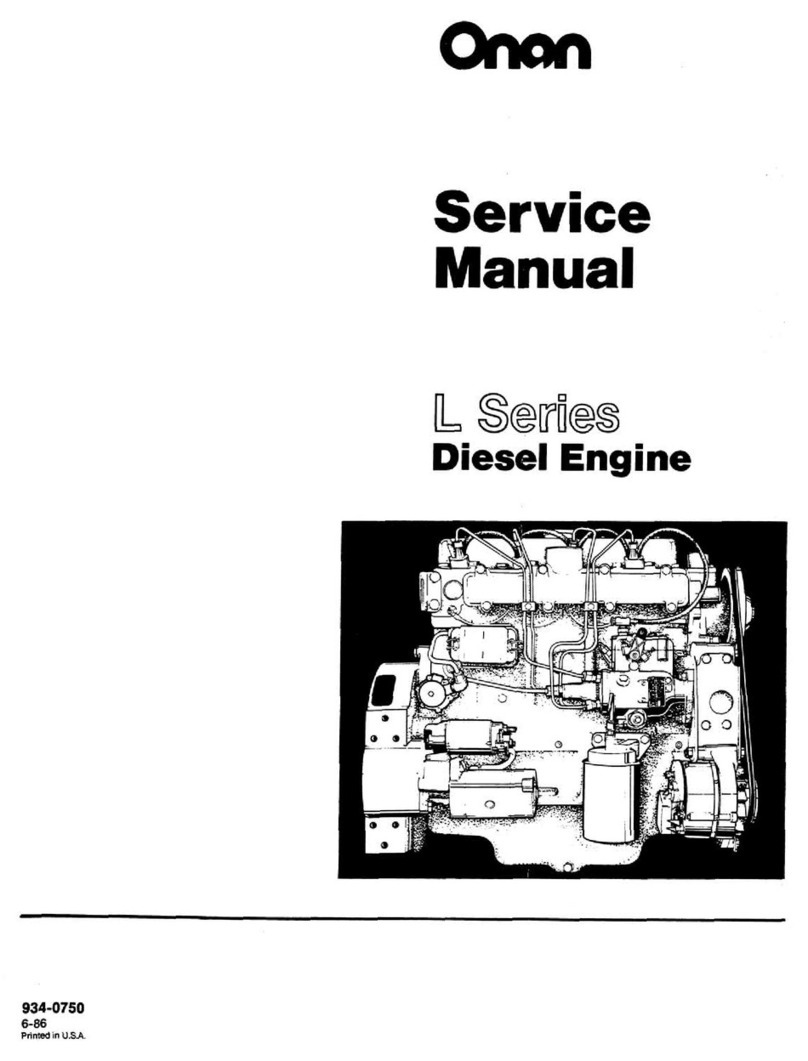
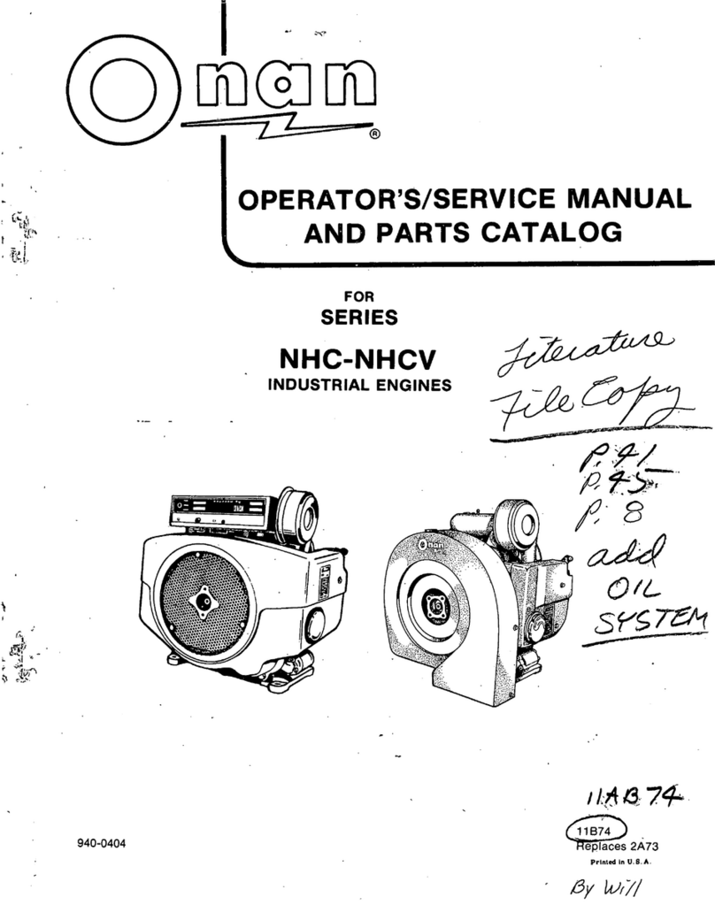
Onan DJA Series Operating manual

1
4
1
,
fDCSOD
^
MANUAL
AND
PARTS
CATALOG
SERIES
DJA
INDUSTRIAL
ENGINES
0
FORMNUMBER
967-0413
Printed
in
U.S.A.
ISSUEDATE
5-79
(SpecA-T)

SAFETY
PRECAUTIONS
Itis.recommendedthatyoureadyourenginemanualand
becomethoroughlyacquaintedwithyourequipmentbefore
youstarttheengine.
WARNING
This
symbol
throughoutthis
is
used
manualto
warnof
possible
serious
personalinjury.
CAUTION
This
symbol
refers
to
possible
equipmentdamage.
Fuels,
electricalequipment,batteries,exhaustgasesand
movingpartspresentpotentialhazardsthatcouldresultin
serious,personalinjury.Takecareinfollowingthese
recommendedprocedures.
SafetyCodes
•Alllocal,stateandfederalcodesshouldbeconsulted
andcomplied
with.
General
•Provideappropriatefireextinguishersandinstallthem
inconvenientlocations.UseanextinguisherratedABC
byNFPA.
•Makesurethatallfastenersontheenginearesecure.
Tightensupportsandclamps,keepguardsinposition
overfans,drivingbelts,etc.
•Ifitisnecessarytomakeadjustmentswhiletheengine-
isrunning,useextremecautionwhenclosetohot
exhausts,movingparts,etc.
ProtectAgainstMovingParts
•Donotwearlooseclothinginthevicinityofmoving
parts,
suchasPTOshafts,flywheels,blowers;
couplings,fans,belts,etc.
•Keepyourhandsawayfrommovingparts.
Batteries
•Beforestartingworkontheengine,,disconnect
batteriestopreventinadvertentstartingoftheengine.
•DONOTSMOKEwhileservicingbatteries.Leadacid
batteriesgiveoffahighlyexplosivehydrogengaswhich
canbeignitedbyflame,electricalarcingorbysmoking.
•Verifybatterypolaritybeforeconnectingbattery
cables.Connectnegativecablelast.
FuelSystem
•DONOTfillfueltankswhileengineisrunning,unless
tanksareoutsideenginecompartment.
•DONOTsmokeoruseanopenflameinthevicinityof
theengineorfueltank.Internalcombustionengine
fuelsarehighlyflammable.
•Fuellinesmustbeofsteelpiping,adequatelysecured,
and,freefromleaks.Pipingattheengineshouldbe
approvedflexibleline.Donotusecopperpipingon
flexiblelinesascopperwillworkhardenandbecome
brittleenoughtobreak.
•Besureallfuelsupplieshavea positiveshutoffvalve.
ExhaustSystem
•Exhaustproductsofanyinternalcombustionengine
aretoxicandcancauseinjury,'ordeathifinhaled.All
engineinstallations,especiallythosewithina confine,
.shouldbeequippedwithanexhaustsystemtodis-
chargegasestotheatmosphere.
•Donotuseexhaustgasestoheata compartment.
•Makesurethatyourexhaustsystemisfreeofleaks.
Ensurethatexhaustmanifoldsaresecureandarenot
warpedbyboltsunevenlytorqued.
EngineExhaustGas(CarbonMonoxide)isDeadly!
Carbonmonoxideisanodorless,colorlessgasformedby
incompletecombustionofhydrocarbonfuels.Carbon
monoxideisa dangerousgasthatcancauseun-
consciousnessandispotentiallylethal.Someofthe
symptomsorsignsofcarbonmonoxideinhalationare:
•Dizziness• Vomiting
•IntenseHeadache• MuscularTwitching
•WeaknessandSleepiness• ThrobbinginTemples
Ifyouexperienceanyoftheabovesymptoms,getoutinto
freshairimmediately.
Thebestprotectionagainstcarbonmonoxideinhalationis
aregularinspectionofthecompleteexhaustsystem.Ifyou
noticea.changeinthesoundorappearanceofexhaust
system,
shut-theunitdownimmediatelyandhaveit
inspectedand'repairedatoncebya competentmechanic.
CoolingSystem
•- Coolantsunderpressurehavea higherboilingpoint
thanwater.DQNOTopena radiatorpressurecapwhile
theengineisrunning.Bleedthesystempressurefirst.
KeeptheUnitandSurroundingAreaClean
•Makesurethatoilyragsarenotleftonornearthe
engine.
•Removealloildeposits.Removeallunnecessarygrease
andoilfromtheunit.Accumulatedgreaseandoilcan
causeoverheatingandsubsequentenginedamageand
maypresenta potentialfirehazard.
TABLE
OF
CONTENTS
TITLEPAGE
GeneralInformation2
Specifications3
DimensionsandClearances4
AssemblyTorquesandSpecialTools6
EngineTroubleshooting7
Installation8
Operation10
ServiceandMaintenance12
CoolingSystem14
FuelSystem16
GovernorSystem24
OilSystem27
StartingSystem29
FlywheelAlternator32
EngineDisassembly' 36
ControlSystem46
WiringDiagrams47
StartingGuide48
PartsCatalog49

DJASeriesengines
are
four
cycle,
vertical,
air-cooled
dieselfueledengineswithoverheadvalves.The
crankcaseandcylinderareintegral.Enginesarerun
inandadjusted
at
thefactory.Anydamageincurredin
transitmustbecorrectedbeforeoperatingthe
engine.SeeFigure1 fora typicalmodelDJAIn-
dustrialEngine,
Normalenginespeed:range
is:
upto2400rpm.An
internal,
constantspeed,flyball-typemechanical
governor,externally,adjustable,is
standard:
Optional
two-speedand:variable-speed:governorsare
available.
Wheninstructions,applytoa specificengine,model,
refertotheenginenameplatefortheModelandSpec
No.
inquestion.
Throughout this, manual the flywheel end will be
calledthe front
and
the fuel pump side
is designated
the/eff
side-..
,
TYPICAL
MODELDJA
FIGURE1.' SERIESOJAINDUSTRIALENGINE
2

SPECIFICATIONS
Nominaldimensionsofengine(inches)
Height24-1/2(622mm)
Width19-1/8(486mm)
Length28-3/16(716mm)
ApproximateWeight(pounds)•..230(104kg)
NumberofCylinders•.1
Displacement(cubicinch)30(.49litre)
Bore3-1/4(82.55mm)
Stroke3-5/8(92.08mm)
HPat2400rpm(nominal)7.3(5.4kW)
CompressionRatio19:1
MainBearingsareSteel-BackedBronze,PrecisionTypefor
Replacement(quantity)2
ConnectingRodBearingsTri-MetalReplaceableYes
PistonRings(chromeplated)- 3rdCompressionRingNOTPlated
OilControl1
Compression3
HardenedChromeAlloyFacedValvesYes
HardenedChromeReplaceableValveSeats.•Yes
ValveRotator:Yes
Governor(internalflyballtype- externallyadjustable}Yes
NominalBatteryVoltage'.12
BatterySize
SAEGroupIHTwo
Amp/Hr.SAE20Hr.(nominal)105(378kC)
SolenoidShiftStarter' Yes
EnginecoolingairCFMat2400
rpm*
' 560(15.86rrvVmin)
Totalcubicfeetperminuteofairrequired613.8(17.38mVmin)
CombustionAirCFMat2400rpm21(.6mVmin)
InletVent(sq.ft.)7 (.7m2)
OutletVent(sq.in.)*64(.04m2)
GlowPlugandAirHeatertoAidStartingYes
InjectionPumpPLB
PrimaryandSecondaryFuelFiltersYes
FuelPumpLift6 ft.(1.8m)
OilPump(GearType)Yes
OilFilter(FullFlow)" Yes
OilCapacity(U.S.quarts)!2-1/2(2.4litres)
ExhaustConnection(Pipe-Tapped); 1-1/4(31.75)
PowerTake-off(inches)
ShaftLength4 (101.16mm)
ShaftDiameter1-3/4(44.45mm)
KeywayLength3 (76.2mm)
KeywayWidth3/8(9.5mm)
KeywayDepth3/16(4.76mm)
*- Pressure-cooledtypeairflow.
-Areawhenventiductisused;withoutduct,makeventaslargeaspossible.
t- Add1/2quart(.5litres)foroilfilter.
3

DIMENSIONSAND
CLEARANCES
All
clearances
givenatroomtemperatureof70°F.
Alldimensionsin
inches
(metricsin
parentheses)
unless
otherwise
specified.
Minimum
Maximum
CAMSHAFT
BearingJournalDiameter,Front.2.500(63.5mm)2.505(63.63mm)
BearingJournalDiameter,Rear
1.1875
(47.63mm)
1.1880
(30.18mm)
BearingClearanceLimit0.0012(.031mm)0.0037(.094mm)
EndPlay,Camshaft0.007(.18mm)0.039(.99mm)
CamTappetHoleDiameter0.7505(19.06mm)0.7515(19.09mm)
CamTappetDiameter0.7475(18.99mm)0.7480(19.00mm)
CONNECTING
RODS
LargeBearingBoreDiameter2.1871(55.55mm)2.1876(55.57mm)
SmallBushingBoreDiameter1.044(26.52mm)1.045(26.54mm)
DistanceCenterLargeBearingBoretoSmall
BushingBore5.998(152.35mm)6.002(152.45mm)
Clearance,LargeBearingtoCrankshaft0.001(.03mm)0.003(.08mm)
CYLINDER
CylinderBore3-1/4(82.55mm)
CylinderDiameterLimits' 3.2495(82.54mm)3.2505(82.56mm)
CRANKSHAFT
MainBearingJournalDiameter2.2437(56.99mm)2.2445(57.01mm)
CrankshaftMainBearingClearance0.0014(.036mm)0.0052(.132mm)
ConnectingRodJournalDiameter2.0597(52.32mm)2.0605(52.34mm)
EndPlay,Crankshaft0.010(.25mm)0.015(.38mm)
PISTON
PistonClearancetoCylinderWall' 0.0055(.140mm)0.0075(.191mm)
PistonPinHoleDiameter0.9900(25.146mm)0.9903(25.153mm)
RingGrooveWidth,Top0.097(2.46mm)0.098(2.49mm)
2nd0.0965(2.45mm)0.0975(2.48mm)
3rd0.0965(2.45mm)0.0975(2.48mm)
4th0.1880(4.78mm)0.1895(4.81mm)
PISTON
PIN
Length2.738(69.55mm)2.753(69.93mm)
Diameter! ' 0.9899(25.14mm)0.9901(25.15mm)
PistonClearanceThumbPushFit
ConnectingRodBushingClearance0.0002(.005mm)0.0007(.018mm)
PISTON
RINGS
RingType
TopCompression
2ndCompression
3rdCompression
4thOilControl
RingWidth
Top0.0925(2.35mm)0.0935(2.37mm)
2nd, 0.0925(2.35mm)0.0935(2.37mm)
3rd0.0925(2.35mm)0.0935(2.37mm)
VALVE
INTAKE(HardenedChromeAlloy
Faced)
StemDiameter0.3381(8.59mm)0.3420(8.69mm)
ClearanceinGuide0.0005(.013mm)0.0025(.064mm)
SeatAngle42-degrees
ValveClearance0.011(.28mm)
4

VALVE,
EXHAUST
(HardenedChromeAlloy)
StemDiameter0.3405(8.65mm)0.3415(8.67mm)
ClearanceinGuide0.0025(.063mm)0.0045(.114mm)
SeatAngle45-degrees
ValveClearance0.008(.20mm)
VALVE
GUIDE
Length•
1-25/32
(45.24mm)
OutsideDiameter0.4690(11.91mm)0.4695(11.93mm)
CylinderBlockBoreDiameter0.467(11.86mm)0.468(11.89mm)
InsideDiameter(afterreaming)
Exhaust0.344(8.74mm)0.345(8.76mm)
Intake0.342(8.69mm)0.343(8.71mm)
VALVE
SEATS
(HardenedChromeAlloy
Faced)
ValveSeatBore
Diameter1.361(34.57mm)1.362(34.59mm)
Depth(fromcylinderheadface)0.433(11.00mm)0.439(11.15mm)"
SeatOutsideDiameter1.364(34.65mm)1.365(34.67mm)
SeatWidth- 3/64(1.19mm)1/16(1.59mm)
SeatAngle45-degrees
AvailableOversizes0.002(.05mm);0.005(.13mm);
0.010(.25mm);0.025(.64mm)-
VALVE
SPRINGS
FreeLength1-7/8(22.23mm)
Length,
ValveClosed1.528(38.81mm)
Load,
ValveClosed45Ibs.(20.41kg)49Ibs.(22.23kg)
Length,
ValveOpen1.214(30.84mm)
Load,
ValveOpen83Ibs.(37.65kg)93Ibs.(42.18kg)
STARTING
MOTOR
RotationCounterclockwise
PinionClearancetoPinionStop
(solenoidplungerbottomed)0.070(1.78mm)0.120(3.05mm)
PinionRestPosition- Distancefrompinionhousing
mountingfacetoouteredgeofpinion
1-9/32
(32.54mm)
1-15/32
(37.31mm)
ArmatureEndPlay005(.13mm)' .030(.76mm)
TestSpecifications
NoLoad10volts- 80amps(288kC)
5000rpmperMin.
StallTorque4 volts- 420amps(1512kC)
7.8ft.Ibs.perMin.(8.8N.m/min)
BrushSpringTension32-40oz.(.91kg- 1.13kg)
withnewbrushes

ASSEMBLY
TORQUES
Theassemblytorquesgivenherewillassureproper
tightnesswithoutdangerofstrippingthreads.Be
carefulnottostripth
reads.
.Use
reasonableforceonly
anda wrenchofnormallength.•
Speciallydesignedplacebolts(Figure2)donot
requirea lockwasherorgasket.Onanusesa-harden-
edflatwasherundereachboltto.preventgallingor
yieldingofbearingplatematerial..Donotattemptto
usea lockwasherwiththesebolts;itwilldefeattheir
purpose.Checkallstuds,nuts,andscrewsxrftenand
tightenasneededtokeepthemfromworkingloose.
FIGURE2.PLACEBOLT
TORQUESPECIFICATIONS
FT.
LBS.
ConnectingRodBolt27-29
Cover-RockerBox8-10
CylinderHeadBolt44-46
ExhaustManifoldNutsfl3-1-5
•FlywheelMountingScrew65-70
FuelPumpMountingScrews15-20
GearCaseCover18-20
GlowPlug10-15
InjectionNozzleMountingScrews....,20-21
InjectionPumpMountingScrews18-21
IntakeManifold13-15
Oil'BaseMountingScrews32-38
OilFilterHandTighten'+1/4to1/2Turn
OilPumpMountingScrews15-20
RearBearingPlate40-45
RockerArmNut*4-10
RockerArmStud35-40
t- Caution:Tightennutsevenlytoavoiddamage.
*- Thistorqueisfromfrictionbetweenthethreadsonlyandlocks
thenutinplace.Therockerarmnutsa'reforadjustingvalve
lash.
SPECIAL
TOOLS
ThesetoolsareavailablefromOnantoaidserviceand
repairwork.
CrankshaftGearPullingRing420-0275
DieselNozzleTester.'.420-0184
DieselPintleNozzleCleaningTool
Set(IncludesInjectionNozzle
CenteringTool)420-0208
NozzleCenteringSleeve....-420-0321
.DeliveryValveTest'Fixturet420-0322
CombinationMainandCamBearing
Driver420-0326
•Driver,ValveSeat420-0270
OilSealGuideandDriver-
BearingPlate420-0250
GearCover420-0281
RidgeReamer420-0260
ReplacementCutterfilade
for420-0260.420-0261
"DieselCompressionTester...420-0283
ValveSeatRemover420-0311
ReplacementBladesfor420-0311420-0274
ValveGuideDriyer...:420-0300
t- Usedwithdieselnozzletester.

DefectiveFuelSystem
AirinFuelSystem
IncorrectTiming
RestrictedAirIntake- DirtyAirFilter
PoorQualityFuel
DirtyFuetFilters
OutcfFuelorShutOffClosed
WornorDamagedTransferPump,LeakingDiaphragm
FaultsInjectionPump,NozzlesorGaskets
FuelLineLeaks
WrongTimingButtoninInjectionPump
WrongThicknessPumpMountingGaskets
RunForLongPeriodsofTimeatNOLOAD
-OilSupply
DefectiveOHGauge
iOilinCrankcase
OilLeaksFromEngineBaseorConnections
LightorDilutedCrankcaseOil
LeakyOilSeals
FaultyOilBy-Pass
WornOilPump
HeavyOilorCloggedPassages
DirtyOilFilter KW.V.W.V.V.V;
•<
GOVERNORSYSTEM
rDisconnectedLinkage
BindiigLinkage
:WearinLinkage
IncorrectGovernorAdjustment
HighSpringSensitivity
IncorrectlyInstalledGovernorYokeorCup
OverloadedGenerator
OLINCSYSTEM;
InsufficientCoolant
FaultyThermostat
WornWaterPumporDefectiveSeals
WaterPassagesRestricted
BlownHeadGasket
Overheating
RestrictedorTooLongWaterLines
DefectiveExpansionTankPressureCap
DirtonCoolingFins(AirCooled)
InadequateAirCirculation(AirCooled)
INTERNALENGINE
LoosePiston
LooseConnectingRodorCrankshaftBearing
Incorr-sctValveClearance
BrokenorWeakValveSpring
HighExhaustBackPressure
VaivesNotSeatingProperly
WornBearings
WornCylinderWalls,'Pistons.Rings
StickingValves
WornorDirtyValveGuides

INSTALLATION
GENERAL
Plantheinstallationcarefullytoensuremaximum
operatingefficiency.Usethismanualasa general
guide.
Recommendationsinthismanualarebasedon
extensivetestsunderfavorableoperatingconditions.
Abidebypertinentlocalcodesregulatinginstallation
aridoperationofinternalcombustionengines.
Protectwallsandpartitionsthroughwhichexhaust
pipespasswitha metalshield(Figure3).
Installa suitablemufflerpreferablyasclosetothe
engineaspracticable.Pitchexhaustpipesdownward,
orprovidea condensationtrapatpointwherearisein
theexhaustsystembegins.
LOCATION
Enginelocationisdeterminedchieflybytheintended
application.Provideadequateaccessforserviceand
repair.Protecttheenginefromadverseweather.
Considerthelocationofrelatedsystems,suchas
fuel,
exhaust,andventilation.
MOUNTING
Securetheenginetoa
rigid,
levelfoundation.Foun-
dationsmustbesturdyenoughtowithstanddistor-
tionandretainalignmentwithloadequipment.
Ifnecessarytoexceed23-degreetiltangle,consult
thefactory.Compensateforanytiltwhenchecking
crankcaseoil.
VENTILATION
Ventilationisneededtocooltheengineandsupport
combustion.Avoidrecirculationofventilatingair.See
SPECIFICATIONSsectionforairflowrequirements
andventsizes.
SINGLETHIMBLEDIAMETER12"
LARGERORDOUBLE
'•^VENTILATEDTHIMBLE
DIAMETER6"LARGER
THANEXHAUSTLINE
HOLESINEND
INNERSLEEVE
EXHAUST
LINE
PASSING
THROUGH
|l
WALL
ORPARTITION
IFEXHAUSTLINEMUSTBEPITCHED
IUPWARDCONSTRUCTA TRAPOFPIPE
FITTINGSATPOINTOFRISE
AVOIDSHARPBENDS 1
DRAINCONDENSATIONTRAP
PERIODICALLY
-FIGURE3.EXHAUST
Locateventssoairflowfromtheinlettotheoutletwill
passovertheengine.Theoutletshouldbeslightly
higherthantheinlet.
Anoptionalairshuttermaybeusedintheoutletduct
tocontrolenginetemperaturebyregulatingairflow.
Airshuttersalsopreventbackflowofcoldairduring
engineshutdown.
Whenshuttersareusedbetweentheengineand
•
outletvent,usea canvassectiontorestrictvibration.
EXHAUST
WARNING| Pipe9asou,sldeanyenclosure.Exhaustgas
^^n^^^^^Jispoisonous.
Exhaustpipesmustnotterminatenearinletvents.
Avoidsharpbendsbyinstallingsweeping,large
radiuselbows.Useflexibleseamlesssectiontubing
betweentheengineandanyrigidpipetorestrict
vibration.
Increasetheexhaustpipeonesizeforeach
additional10-footlength.
FUEL
TANKAND
LINES
Installthefueltanksothattheverticaldistancefrom
bottomofthetanktothefuelpumpdoesnotexceed
sixfeet.Auxiliaryfuelpumpsareavailablewhich
provideanadditionaleight-footfuellift.
Avoidgravityfeedoffueltotheengine.Providea
siphonbreakiftankisabovepump.Whensharinga
fueltank,donotconnecttoanexistinglineata point
abovethefuelsupplylevel.
Thesedieselenginesrequirea fuelsupplylineanda
separatereturnline.Installthefuelsupplylinefrom
tanktothe
1/8-inch
pipeinletinthefuelpump.
Connectthefuelreturnlinetothefitting(7/16-24
size)ontheinjectionpump(Figure4)tothetopofthe
fuelsupplytank.Useapprovedflexiblefuellinesat
theenginetoabsorbvibration.Besuretherearenoair
leaksinthesuctionline.

Donotusegalvanizedlines,fittingsorfueltanks.Carefullycleanall
fuelsystemcomponentsbeforeputtingtheengineintooperation.
Anydirtorcontaminationmaycausemajordamagetothefuel
injectionsystem.
BeginningwithSpecS,a newfuelfiltrationsystem
accommodatesbothprimaryandsecondaryfuel
filtersonacommonmountingcastingwhichisbolted
toanewlydesignedoilfill
tube.
Theenginecannotbe
runwitheitherfilterlooseormissing,thusensuring
properfiltrationatalltimes.
AIR
CLEANER
MANIFOLD
HEATER
SLOWPLUG
CRANKCASE
BREATHERTUBE
FUEL
RETURNLINE
FUELFILTER
SEDIMENT
BOWL
PRIMARY
FUELFILTER
INJECTION
NOZZLE
INJECTION
PUMP
SECONDARY
FUELFILTER
FIGURE4.FUELSYSTEM
BATTERY
Mountthebatteriesonawoodormetalracknearthe
engine.Aircirculationaroundthebattery
is
essential.
Usenumber2 batterycablesoftheproperlengthto
limitvoltagedrop.
STATOR
BATTERY
CONNECTIONS
Batteriesforenginesequippedwithoptionalflywheel
alternatorsmustbenegativelygrounded.A 30amp
fuseprotectstherectifiershouldthebatterybe
connectedwithreversepolarity(Figure6).Onearly
modelswithoutfuse,destructionoftherectifierwill
result.
Connecttheremainingbatterycabletothelarger
terminalonthestartingmotorsolenoid(Figure5).
OIL
DRAIN
EXTENSION
Forserviceconvenience,install
an
oildrainextension
madefromstandardpipeandfittings,inthe
1/2-inch
pipetappedoilbasedrainhole.
STARTING
MOTOR
BATTERY
NEGATIVE
I2-V.BATTERY
FIGURE5..SOLENOIDWIRING
FUSEHOLDERWITH
30-AMPEREFUSE
ROTOR
REGULATOR-RECTIFIER
ASSEMBLY CONNECTOR
FIGURE6.FLYWHEELALTERNATOR(BEGINNINGWITHSPECT)
9

OPERATION
CRANKCASE
OIL
UseanoilwiththeAPIdesignationCD/SEorCD/SD.
However,toreduceoilconsumptiontoa normallevel
intheshortesttimepossibleona neworrebuilt
engine,useCCoilforthefirstfillonly(50hours).
Thenusetherecommendedoilonly.Selectthe
correctSAEgradeoilbyreferringtothefollowing.
TEMPERATURE
GRADE
Above30°
F
SAE30
0°
F
to30°
F
SAE10Wor5W-30
Below0oFSAE5W-30
Multigradeoilsarerecommendedfortemperaturesof
30°
F
andbelow,buttheyarenotrecommendedfor
temperaturesabove30oF.Whenaddingoilbetween
oilchanges,itispreferabletousethesamebrandas
inthecrankcase.Variousbrandsofoilmaynotbe
compatiblewhenmixed:together.
Iftheoilsupplyinyour
local
areastill
has
the
API
designationsML,
MM,
MS,
DC,
DMand
OS,
use
an
oilwiththe
DS
designationwhich
haspassedtheSeries3 TestandatleastSequence1 ofthe
AutomotiveManufacturer'sMSSequenceTests.Toreduceoil
consumptiontoa normallevelIntheshortesttimeona newor
rebuiltengine,use
DG
or
DM
oil(passingthe
MS
SequenceTests)
forthefirstfillonly
(SO
hours).
Thenusetherecommended
oil.
See
SERVICEANDMAINTENANCE
seciion
forsuggested
oil
changes.
OIL
BATHAIR
CLEANER
(Optional)
Usethesamegradeofoilintheaircleanerasisused
inthecrankcase.Theproperlevelismarkedontheair
cleaner.
RECOMMENDED
FUEL
UseASTM2-Dor1-Dfuelwitha minimumCetane
numberof45*.Number2 dieselfuelgivesthebest
economyformostoperatingconditions;however,
useASTM1-Dfuelduringthefollowingconditions:
1.
Whenambienttemperaturesarebelow32°F.
2.
Duringlongperiodsoflightengine
load;
orno
load.
"FuelswithCetanenumbershigherthan45maybeneededin
higheraltitudesorwhenextremelylowambienttemperaturesare
encounteredto
prevent,
misfires.
Uselowsulfurcontentfuelhavingapourpoint(ability
tofilter)ofatleast10oFbelowthelowestexpected
temperature.Keepthefuelcleanandprotectedfrom
adverseweather.Leavesomeroomforexpansion
whenfillingthefueltank.
CAUTION Duetotheprecisetolerancesofdieselinjec-
tion
systems,
Itisextremelyimportant
the
fuel
bekept
clean.
Dirtinthesystemcancauseseveredamagetoboth
theinjectionpumpandtheInjectionnozzles.
INITIAL
START
Checktheenginetomakesureithasbeenfilledwith
oiland
fuel.
Ifnecessarytoprimea dryfuelsystem,
returnthepriminglevertothedisengagedposition
afterpriming.Formoredetailedstartinginformation
seeStartingGuide,page48.
Thisunithasbeenmnandtestedforapproximatelyfourhoursat
thefactory.Additionalbreak-intimeisrequired andwillvary
dependinguponloadconditions,oilused,etc.
Run as follows:
1.
Noload15-20minutes
2.
One-thirdload30minutes
3.Two-thirdsload2 to3 hours
Thenregularoperationcanberesumed.Avoidlight
loadoperationduringthefollowingseveralhoursfor
bestringseatingtocontroloil.
STARTING
1.
Whenstartinga coldengineinambientsabove
.550F,
preheatfor20seconds.
2.
Continuetoholdpreheatswitch:
a.PushthefuelsolenoidtoitsONposition.
b.PresstheSTARTswitch.
3.Releasestartswitchafterenginestartsand
reachesspeed.
4.
Oilpressureshouldreadatleast20psi.Pressure
reliefvalveisnotadjustable.
Whenstartingattemperaturesbelow55°F,orunder
highhumidityconditions,refertosuggestedstarting
aidsinLowTemperaturesparagraph.
Whenrestartingengineaftershortperiodsofshut-
down,
preheatingisusuallynotnecessary.
STOPPING
Disconnectasmuchloadaspracticalfromtheengine
beforeshutdown..Pushthefuelsolenoidswitchtoits
OFFposition(thisde-energizesthesolenoid,closing
thethrottle).
CAUTION Carbonintheexhaustsystemwilloccurin
dieselenginesoperatedconsistentlyatlight
loads.
Occasionallyoperateengineatfullload(oraboutfive
minutesbeforestopping)tocleanouttheexhaustsystem.
10

APPLYING
THE
LOAD
Applytheloadfornewandreconditionedenginesin
foursteps.Wait30minutesbetweeneachstep.If
practical,
allowtheengineto
warm
upbeforeconnec-
tinga heavy
load.
Trytoconnecttheloadinsteps
insteadofthefullloadatonetime.
INSPECTION
Checkforalignmentofengineand
load.
Misalign-
mentwillcauseexcessivevibrationandbearingwear.
Makea visualinspectionoftheentireinstallation.
PROTECTION
FOR
EXTENDED
OUT-OF-SERVICE
PERIOD
1.
Runengineuntilthoroughlywarm.
2.
Draintheoilbasewhilestillwarm.Attacha
warningtagtorefillbeforeoperating.
3.Servicetheaircleaner.
4.
Lubricategovernorlinkage.Protectfromdirtby
wrappingwitha cleancloth.
5.Plugexhaustoutletto
keep
out
moistu
re
and
dirt.
6.Cleanentireunit.Coatpartslikelytorustwith
lightgreaseoroil.
7.Providea suitablecoverfortheentireunit.
8.Disconnectbatteryandfollowstandardbattery
storage proced
u
res.
HIGH
TEMPERATURES
1.
See
thatnothingobstructsairflow
to
and
fromthe
engine.
2.
Besuretheroomisproperlyventilated.
3.Keepthecoolingfins
clean.
Seethatairhousings
areproperlyinstalledandundamaged.
LOW
TEMPERATURES
1.
UsecorrectSAENo.oilfortemperature
con-
ditions.Changeoilonlywhenengjneiswarm.If
anunexpectedtemperaturedropcausesan
emergency,moveenginetoa warmlocationor
applyexternallyheatedairuntildilflowsfreely
(donotuseanopenflame).-j
2.
Preheatforoneminuteifthetemperatureis
55°F
orlower.Ifenginefailstostartaftbrcrankingfor
oneminute,preheatforoneminutemoreandre-
attemptthestart.Inextremecoldtemperatureit
maybenecessarytomaintainpreheatingupto2
minutesaftertheenginestartstosustainfiringor
tosmoothoutallcylinders,especiallyatnoload
orlightloads.
CAUTION Donotusepreheatformorethanone
minutebefore
cranking.
Thiswillhelpto
preventheaterbum-outandconservebatterypower.
3.Protectfuelagainstcondensation.
4.
Keepbatteriesina well-chargedcondition.
5.Reduceroomventilation,butusecaretoavoid
overheating.
DUST
ANDDIRT
1.
Keepengineclean.
2.
Serviceaircleanerasoftenasnecessary.
3.Changecrankcaseoilevery50operatinghours.
4.
Keepoilandfuelsuppliesindust-tight
con-
tainers.
5.
Keep
governorlinkage
connections
clean.
HIGH
ALTITUDE
Maximumenginepowerwillbereducedabout4
percentforeach1000feetabovesealevel.
11

SERVICE
AND
•
Beforeengine
isputin
operation,check
all
com-
ponents
for
mechanicalsecurity.
Ifan
abnormal
condition,
defectivepart,
or
operatingdifficulty
is
detected,
repair
or
sen/ice
as
required.SeeFigure
7
forserviceandmaintenance-instructions.Theengine
shouldbekeptfree
of
dust,dirt,andspilledoilorfuel.
Besureproperoperating-procedure
is
followed.
ENGINE
ROUTINE
CHECK
CHART
WHAT
TO
CHECK
HOWTO
CHECK
PRECAUTIONS
Engine
oil
Checklevel(should
beat
fullmark
on
indicator). Add
oilas
necessary
to
bringlevel
to
full
mark.
Donot
overfill.
Enginefuel Checklevel
in
tank. Seethatfuellines
are
properlyconnected.
Engineventilation Checkventilatingopenings. Remove
any
obstructions.
Connectingcables Check
fbr
properconnections.
Check
for
physicaldamage. Tightenconnections.
Replacedamagedconnectors.
Battery Checkelectrolytelevel. Keeplevelaboveplates.
Addonlydistilledwaterasnecessary.
MAINTENANCE
SCHEDULE
Usethisfactoryrecommendedmaintenance(based,
onfavorableoperatingconditions)to
serve
as
a
guide
to
get
long
and
efficientenginelife.Neglecting
routinemaintenance
can
result
in
failure
or
perma-
nentdamage
tothe
engine.
Maintenance
is
dividedinto
two
categories:
(1)
OperatorMaintenance
—
performedbytheoperator,
and
(2)
CriticalMaintenance
—
performed
by
qualifiedservicepersonnel.
OPERATOR
MAINTENANCE
SCHEDULE
CRITICAL
MAINTENANCE
SCHEDULE
MAINTENANCE
ITEMS OPERATIONALHOURS
MAINTENANCE
ITEMS 8 50 100 200 600 3000
InspectEngine X
CheckFuel x3
Gheck
Oil
Level X
CheckExhaustSystem
•
X
Check
Air
Cleaner xl
CleanGovernorLinkage xl
ChangeCrankcase
Oil
xl-2
DrainCondensationTraps x3
CheckBattery X
Replace
Oil
Filter Xl
CleanCrankcaseBreather X
ChangePrimaryFuelFilter x3
ChangeSec.FuelFilter X
MAINTENANCE
ITEMS
OPERATIONALHOURS
MAINTENANCE
ITEMS 500
| 1000
2000
|
5000
CheckValveClearance x4
ReplaceSecondaryFuelFilter x3
CleanEngine X
CleanRocker
BoxOil
Line
Holes X
InspectValves;Grind
if
Necessary X
Remove
and
Glean
Oil
Base X
CheckInjectionNozzles x6
GeneralOverhaul x5
xl
-
Moreoftenunderextremelydustyconditions.
x2
-
CD/SD
or
CD/SE
oil
preferred.
UseCCoil
first
50
hours
for
break-in.
x3
-
Water
or
foreignmaterial
inthe
fuel
can
ruin
the
injection
system.
If
dailyinspectionshowswater
or
excessivedirt
in
primaryfilterbowl,fuelhandlingandstoringfacilitiesshould
bechecked
and
situationcorrected.Primaryfuelfiltermust
becleaned
and
secondaryfuelfilterreplacedfollowing
correction
of
fuelcontaminationproblem.
x4
-
Tightenheadbolts
and
adjustvalveclearanceafterfirst
50
hours
ona newor
overhauledengine.
x5
- Oras
required.
x6
-
Thisservicemust
be
performed
by
traineddieselinjection
equipmentpersonnelwithsuitabletestfacilities.Omitthis
serviceuntiltheseconditions
canbemet.
For
any
abnormalities
in
operation,unusualnoises,loss
of
power,
overheating,
etc.,
contactyourOnandealer.
12

BREATHER
HOSE
HOSE
CLAM
CAPANDVALVE CLAMP
BAFFLE
BREATHER
TUBE
—
CRANKCASEBREATHER
BeginningSpec
R
Removehoseclamp,breatherhose,
insulatorclamp,insulatorhalves,
and
breather
cap
clamp.Wash
cap,
valve
assembly,
and
baffle
in
suitablesolvent
andreinstall.
FUELFILTER
BODY
FILTER
SCREEN
GASKET
BOWL
AIR
CLEANER
(OPTIONAL)
KEEP
OIL
ATTHIS
LEVE
oe o o
o e
o
«
OOOOOOO'
OOOOOOO*
O
O O 0 O 0 0
<
BREATHERTUBE
CAP
FLAPPER
VALVE
ASSEMBLY
TUBE
FROM
AIR
CLEANER
:VE:L—^DILLgyiTI^J
OILFILTERCHANGE
(SeeSchedule)
Place
pan
under
old
filter
and
remove
by
turningcounterclock-
wise.
Cleanfiltermountingarea.
Install
new
filter;
oil
filtergasket
andscrewfilter
on
clockwise
untilgaskettouchesmounting
base,
thentighten
1/2
turn.
BREATHER
TUBEBAFFLE
CRANKCASEBREATHER
Prior
to
Spec
R
Removebreather
cap.
Removevalvefrom
cap.
Washvalve
ina
suitablesolvent.
Dry
and
installwithperforateddisc
towardengine.
If
faulty,install
new
valve.
ALWAYSREPLACE
CAP
TIGHUY.OR
Oil
LEAKAGE
MAYOCCUR.
CAPANDOILLEVEL
INDICATOR
NEVER
OPERATEENGINE
WITH
OILI
THIS
I
AFTERWASHINGELEMENT
DIP
INENGINE
OILAND
SQUEEZE
AS
DRYAS
POSSIBLE.
AIRCLEANER
ELEMENT
AINER
CONNECTOR
(Fromfuel
transferpump)
ELBOW
(Toinjection
pump)
DRAIN—PRIMARY8*
FILTER
\
SECONDARY
FILTER
DRAIN
MODELSBEGINNINGWITHSPEC
S
Drain
water
periodically
asrequired
from
both
filters
and
sediment
bowl.
Replace
primary
filter
every600hoursand
secondary
filter
every3000hours.Whenreplacing
filter,
tighten
screw
until
gaskettouches
base,
thentighten
screw
1
to1-1/2turns.
FIGURE
7.
MAINTENANCEPROCEDURES
13

COOLING
SYSTEM
Toremoveheatproducedduringoperation,engines
usea pressureair-coolingsystem.Bladesonthe
engineflywheeldrawairinthefrontoftheengine
housing,
forcetheairpastthecylinderandoutthe
rightsideoftheengine.SeeFigure8.
Fromtheengineoutlet,aircanbeductedoutofthe
area.
Toimproveenginetemperaturecontrol,an
optionalshutterassemblycanbeinstalledontheair
outlet.SeeFigure9.
MAINTENANCE
Withaproperlyinstalledengine,maintenanceshould
consistofcleaningtheenginecoolingarea(finson
cylinderblockandcylinderhead)atregularintervals,
normallyevery
1000
hoursbutmoreoftenunderdirty
operatingconditions.
OVERHEATING
This
is
sometimesdifficult
to
discover
in
an
air-cooled
engine.However,thefirstsignisusuallyengine
losingspeedmomentarilyorlowenginepower.This
happensbeforetheengineseizesandresultsina
scoredpiston.
Themostprobablecausesofoverheatingaredirty
coolingsurfaces,operatingwithouttheengineair
housing,
pooraircirculation,improperlubrication,
wronginjectiontimingandengineoverload.
CAUTION Theair
housing
includingthedoormustbeon
whenoperatingtheengine.Overtteatingand
permanentdamagecouldresultfromaslittleasoneminuteof
operationwithoutit.
Commoninstallationproblemsleadingtoover-
heatingareasfollows:x
1.
Installationwithductsizetoosmallsoairflowis
insufficient.
2.
Installationinsmallroomwithnoductsand
insufficientairventilationintheroom.
3.Installationofairinletandoutletductssoair
outletfeedsbacktotheinlet.
AIR
SHUTTER
(Optional)
Theoptionalairshutterassemblyismountedatthe
engineairoutlet,ontherightsideoffhecylinder
shroud.
A thermostaticelement(Figure10)controls
theshutterssotheycloseandlimitairflowwhenthe
airtemperaturereaches120°F.Thepowerelement
plungerbeginstomoveoutward,openingthe
shuttersuntiltheyarecompletelyopenby
140°
F.
Shutteropeningtemperatureisnotadjustable,butto
assurecomplete
opening,
thepowerelementplunger
mustcontacttheshutterrollpinat
room
temperature.
Toadjustthis,loosenthepowerelementmounting
screws
and
slidetheassemblyuntilittouchestheroll
pinwiththeshutter.closed.
BLOWER
HOUSING
ACCESS
DOOR
AIRIN
BLOWER
WHEEL
AIRDUCT
-AND
SHUTTER
FIGURE8.COOLINGAIRFLOW FIGURE9.AIRDUCTANDSHUTTER
14

Repair
Iftheshutterwillnot
open,
checkthepowerelement
fordefectsorbindingoftheplunger.Besurethe
shutterdoesnotbindagainstthehousinginany
position.
Totestthepowerelement,removeitfromthe
assemblyandheatit.Whentheunitreachesabout
120oF,
theplungershouldstarttomoveout.Total
movementshouldbeatleast1/5-inch.Donot
overheat.
Iftheunitwillnotclose,checkfora weakreturn
spring,
bindinginthenylonbearingsordirtinthe
powerelementplunger.Ifthenylonbearingsare
wornor
bind,
replace
them.
Removetheshuttersand
pulloutthestubshaft.Pushouttheoldandpushin
newbearingsfromtheinsideoftheshutterhousing.
Thelargebearingsurfaceserves
as
a
spacerbushing
soitmustbeontheinsideofthehousing.The
shuttersshouldbeadjustedtoobtainanendthrust
clearanceofnotmorethan1/32-inch.
HIGH
TEMPERATURE
CUT-OFF
Whenoptionalautomaticairdischargeshutteris
used,
itisrecommendedthattheshutterincludea
hightemperaturecut-off
switch.
Thisswitchprotects
theengineifshutterfailstoopen.Theswitchisin
serieswiththegovernor
solenoid.
Switchisnormally
closedandopensatabout
240°
F.
Whenit
opens,
the
solenoidisde-energized,stoppingtheunit.The
switchclosesagainatabout1950F.
LATEMODELS
UPPERSHUTTER
ACTUATINGROD
SHUTTERS
EARLY
MODELS
SHUTTER
ACTUATING
ADJUST
THE
VERNATHERM
POWER
ELEMENT
TOREST
ONTHEROLLPIN
WITH
SHUTTER
CLOSED
AT
AMBIENT
TEMPERATURE
VERNATHERM
POWER
ELEMENT
LOWER
SHUTTER
ACTUATING
ROD
ADJUST
THE
VERNATHERM
POWER
ELEMENT
TOREST
ONTHEROLLPIN
WITH
SHUTTER
CLOSED
AT
AMBIENT
TEMPERATURE
VERNATHERM
BRACKET
ADJUSTINGAND
MOUNTING
SCREWS
INSLOTTED
HOLES
FIGURE
10.
AIR
SHUTTER
15

FUEL
SYSTEM
Thedieselfuelsystemprovidesa means
of
filtering,
transportinganddeliveringfuel
in
afinespraytothe
enginecylinder
at
thecorrecttime
for
ignition.
The
systemconsists
of
a
primaryfuelfilter,fueltransfer
pump,
secondaryfuelfilter,injectionpump
and
an
injectionnozzle.SeeFigure11.
Thediaphragmfueltransferpumpwhichoperates
directly
off
the
enginecamshaft,drawsfuelfrom
a
supplytankanddelivers
it
throughtwofilterstothe
injectionpump.Theinjectionpumpmetersfuel
and
delivers
it,at
highpressuretotheinjectionnozzle
at
thecorrecttime
for
ignition.
Theinjectionnozzleopens
at
a.
set
fuelpressure,
deliveringfuel
in
a finespray,
to
theprecombustion
chamber
for
ignition.
The
nozzleremainsopen,
deliveringfuel
as
longas,thefuelpressureremains
abovethecriticalpoint.
Extra
fuel
isbledoffafter
each
injectioncycleby
a
fuel
returnlinefromthenozzle.Anadaptercombinesthe
returnfuelwith
the
flow-throughfuelfrom
the
injectionpump.
A
returnlineconnected.atthispoint,
returns
the
combinedfuelback
to
the
fuelsupply
tank.
CAUTION^
D,rtln,he'uel
8y8,em
l8a
dieselengine's
worstenemy.
It
Isoneofthemajorcauses
of
dieselengine
failure.
Even
a
tiny
piece
ofdirt
in
theInjectionsystem
maystopyourunit
When,
opening
any
partof.thefuelsystem
beyondthesecondaryfuelfilter,placeallpartsIn
a
pan
of
clean
dieselfuel
as
they
are
removed.
Before
installingnewor
used
parts,
flushthemthoroughlyandInstallwhilestillwet.
MAINTENANCE
Inaddition
to
regularserviceperiods,change
the
secondaryfuelfiltercartridge
if
the
engineshows
signs
of
starvingfromlack
of
fuel..
Remove
the
secondaryfilter
by
removing
the
largecapscrew
in
thecenterofthefiltercover.Use
care
when
replacing
thefiltercartridge
to
avoidgettingdirtinto
the
injectionpumppassages.
Whenreplacing
or
cleaningfilters,bleed
the
fuel
system.
Do
this
by
opening
theair
bleedscrew
located
on
top
of
the
secondaryfilterremoval
cap
screw.Operatethehandpriminglever
on
thetransfer
pumpuntilno
air
bubblesflowfromthebleedscrew
hole,
thentightenthe
bleed
screw.Returnthepriming
lever
toits
originalposition.SeeFigure
12.
Ifthetransferpumpcamlobe
is
on
thehigh
side,
thepriminglever
will
not
operatethepump.Tumtheengineonerevolutionbefore
operatingthepriminglever.
AIR
CLEANER
MANIFOLD
HEATER
6LOWPLUS
CRANKCASE
BREATHERTUBE
FUEL
RETURNLINE
FUELFILTER
SEDIMENT
BOWL
PRIMARY
FUELFILTER
INJECTION
NOZZLE
INJECTION-
PUMP
'
SECONDARY
FUELFILTER
WORK
TRANSFE
R
PUMP
PRIMING
LEVER
To
FILU
FILTER
NOTE:IF
PRIMING
LEVER
DOES
NOT
ENGAGECRANK
ENGINE
ONE
REVOLUTION.
REMOVE
BLEEDPLUG
FROM
TOP
OF
FUEL
FILTER
ALLOW
FUEL
TOFLOW
FROM
BLEEDER
HOLE
UNTIL
NO
A::RBUBBLES
APPEAR.
FIGURE11.DIESELFUELSYSTEM(BEGINNING
WITHSPEC
S)
FIGURE
12.
BLEEDINGFUELSYSTEM
(PRIORTOSPECS)
16

FUEL
TRANSFER
PUMP
Thetransferpumpislocatedontheleftsideofthe
engine.Iffueldoesnotreachthesecondaryfilter,
makethefollowingchecksbeforeremovingthe
pump.
1.
Checkthefueltankandseethattheshutoffvalve
isopen.
2.
Removethefuellinefromthetransferpump
outletandworktheprimingleveronthepump.
Fuelshouldspurtoutofthepump.Ifnot,remove
thepumpforrepairorreplacement.
Testing
Ifthetransferpumpdelivers
fuel,
testitwitha
pressuregaugeormanometer.Performthesetests
beforeremovingthepumpfromtheengine.Remove
thepumpoutletandinstallthepressuregauge.See
Figure15.
Testthevalvesanddiaphragmbyoperatingthe
primerleverafewtimesandwatchingthepressure.It
shouldnotdropoffrapidlyafterpriminghasstopped.
Nextruntheengineatgovernedspeedonfuel
providedbygravityfeedandmeasurethefuelpump
pressuredeveloped.Pressureshouldbebetween5
and6 psiwiththegauge16inchesabovethefuel
pump.
Alowpressurereadingindicatesextremewearinone
partorsomewear
in
allparts,andthepumpshouldbe
overhauledorreplaced.Ifthereadingisabove
maximum,thediaphragmisprobablytootightorthe
diaphragmspringtoostrong.Thiscanalsobecaused
byfuelseepingunderthediaphragmretainernutand
betweenthediaphragmlayers,causinga bulgeinthe
diaphragm.Overhaulthepumpandreplacethe
defectiveparts.SeeFigure16.
Lowpressurewithlittleornopressureleakafter
pumpingstopsindicatesa weakorbrokenspringor
wornlinkageandinmostcasesthepumpshouldbe
replaced.
Repair
Transferpumpfailureisusuallyduetoa leaking
diaphragm,valveorvalvegasket.A kitisavailablefor
replacementofvariousparts.Becausetheextentof
wearcannotbedetectedbytheeye,replaceallparts
inthekit.Ifthediaphragmisbrokenorleaks,check
fordilutedcrankcaseoilandreplace.
Occasionally,failureisduetoabrokenorweakspring
orwearinthelinkage.Inthiscase,replacetheworn
partsorinstalla newpump.Obtainreplacementparts
orinstalla newpump.Obtainreplacementpartsother
thantherepairkitfromanoriginalequipmentparts
distributor.
UPPERPUMPBODY
GASKET
VALVEANDCAGE
DIAPHRAGM
ROCKERARM
SPRING
DIAPHRAGM
SPRING
LOWER
PUMPBODY ftV ROCKERARMAND
7LINKASSEMBLY
t„ ROCKER
>,^$ARMPIN
FIGURE13.EXPLODEDVIEWOFJ-SERIESPUMP
Fuel
PumpRemoval
Disassembly
1.
Afterthepumpisremovedfromtheeng
ine,
scribe
alineontheflangesoftheupperandlowerpump
bodiestoassurecorrectpositioningwhen
reassembling.
2.
Removethesecuringscrewsandseparatethe
upperandlowerpumpbodies(Figure13).
3.Torelease thepumpdiaphragm,pressdownon
thebaseofthediaphragmattheedgefarthest
fromthepumpmountingflange.Withoutreleas-
ingthisedge,pressdownontheoppositeedge.
Thisactionwillunhookthediaphragmactuating
rodfromtherockerarmlink(Figure14).
4.
Withtheaidofa pliersorscrewdriver,pushand
tiptherockerarmreturnspringoffthecatchon
therockerarmandremovefrompump.
5.Cleanandinspectallpumpcomponentsnot
includedintherepairkit.Ifdamageisapparent,
replacethepump.
ThevalveandcageassembliesonIheJ seriespumpare
permanentlymountedintheupperbodyofthepump.Ifthe
assembliesaredamagedornoticeablyworn,theentirepump
mustbereplaced.
17

PRESSDOWNONDIAPHRAGMBASEHERE
DIAPHRAGM
ROCKERARM
STEPONE
CONTINUETOPRESSHERE
PRESSDOWNHERETOTIPDIAPHRAGM
RODOFFROCKERARMLINK
DIAPHRAGM
ROCKERARM
STEPTWO
FIGURE14.REMOVALOFJ-SERIESDIAPHRAGMASSEMBLY
Assembly
1.
Lubricatethediaphragmactuatingrodandinstall
thenewdiaphragminthepump.Reversethe
procedureusedforremoval,rollingbackthe
diaphragmfabrictoviewtherockerarmlink
(Figure14).Holdthepumpbodyupside-downso
thattheweightofthelinkwillkeepitwithinreach
ofthediaphragmactuatingrod.
2.
Installthenewrockerarmreturnspring..
3.Placetheupperandlowerbodiesofthepump
,togetherwiththescribemarksaligned.Startthe
sixsecuringscrews,makingsuretheydonot
chewintothediaphragmfabric.Leavethescrews
2or3 turnsloose.
4.
Operatetherockerarmseveraltimestofullyflex
thenewdiaphragm.Whileholdingtherockerarm
fullyflexed,tightenthesecuringscrews.
Failuretofullyflextherockerarmwhile
tighteningthepumpbodiestogetherwill
resultinexcessivepumppressureandpossibleengine
floodingorpumpdiaphragmfailure.
CAUTION
NOZZLE
Theinjectionnozzleistheconventionalinward
openingpintletypewithadjustableopeningpressure.
Itisfactoryadjustedtoopenat1900to1950
psi.
After
severalhundredhoursofoperationthenozzle
pressurewilldecreasetoapproximately1750psi.Do
notdisassemblethenozzleoradjustnozzlepressure
withoutpropertestequipment.A nozzlepressure
testerisessentialtodothiswork.
FUELPUMP1
OUTLET
FIGURE15.FUELPRESSUREGAUGE
Inspection
Toinspectthenozzlespraypattern,removethe
nozzlefromthecylinderhead.Cranktheengine,let
thenozzlesprayintotheairandwatchthepattern.
Thesprayshouldbeconeshapedwitha solid
appearingcentersurroundedbycloudlikefogin
whichthesprayisevenlyatomized.SeeFigure
17.
An
apparentchatteringofthenozzleisnormal.
Ifstreamer'sarevisible,thepatternisbadlydistorted
orthenozzledripsbeforeitreachesopening
pressure,itisdefectiveandmustbecleanedor
replaced.
WARNING
seriousinfection.
Donotletthenozzlesprayagainstyour
skin.
Thefuelcanpenetratefleshandcausea
Adjustment
Toadjusttheopeningpressure,removethenozzle
fromtheengine.Removethecapnutoverthe
adjustingscrewofthenozzleandinstallthenozzleon
astaticfuelnozzletestingfixture(maybepurchased
fromOnan).Followingthetesterinstructions,adjust
theopeningpressureto1750psibyturningthe
adjustingscrew.SeeFigure18.Clockwiseincreases
thepressureandcounterclockwisedecreasesit.Do
nottryto
adj
ustthepressurewithout
a
testi
ng
fixtu
re.
18
This manual suits for next models
3
Table of contents
Other Onan Engine manuals

Onan
Onan Performer P216 User manual

Onan
Onan L Series User manual

Onan
Onan Performer P216 User manual

Onan
Onan Elite E125V User manual

Onan
Onan RDJC User manual

Onan
Onan Elite E125V User manual

Onan
Onan B43M User manual

Onan
Onan NHC User manual

Onan
Onan RDJE User manual

Onan
Onan NHC Series Instruction Manual