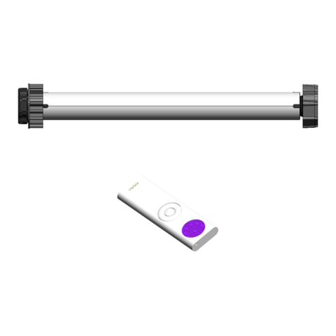
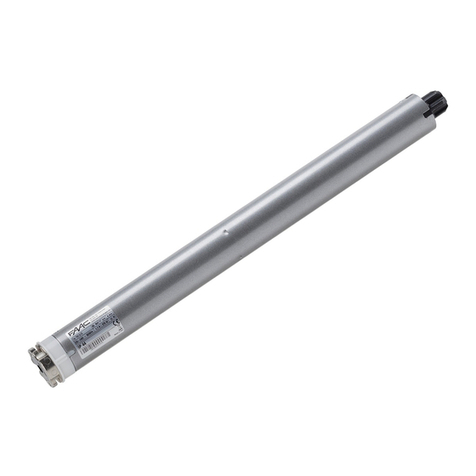
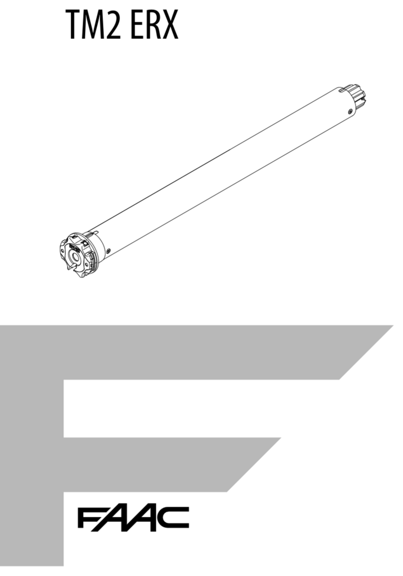
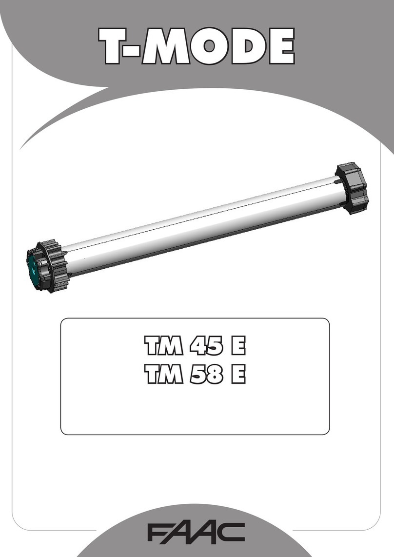
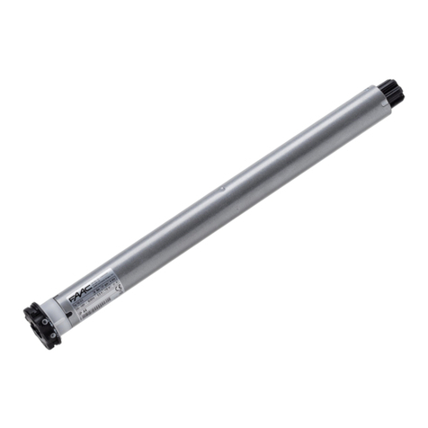
FAAC T-MODE TM R User manual

T-MODE
TM R-W 868 Mhz

ENGLISH
2
WARNINGS FOR THE INSTALLER
DECLARATION OF CONFORMITY
Manufacturer: FAAC S.p.A.
Address: Via Calari, 10 - 40069 Zola Predosa BOLOGNA - ITALY
Declares that: Operator mod. TM 45 radio - wind
• conformstotheessentialrequirementsofthefollowingEECdirectives:
-2006/95/EEC
- 2004/108/EEC
-99/05/EEC
•itthusconformstothefollowingharmonisedstandards:
-EN60335-1-95,EN60335-2-97/10-2000.
-EN61000-3-2,EN61000-3-3,
-EN55014-1,EN55014-2
Bologna,01/12/2012 TheManagingDirector
A. Marcellan
1. ATTENTION! To ensure the safety of people, it is important that
you read all the following instructions. Incorrect installation or
incorrect use of the product could cause serious harm to people.
Keep these instructions for future reference.
2. Carefully read the instructions before beginning to install the
product.
3. This product was designed and manufactured exclusively for
thepurposeindicatedinthisdocumentation.Anyotheruse,not
expresslyindicatedhere,couldcompromisethegoodcondition/
operationoftheproductand/orbeasourceofdanger.
4. FAACdeclinesanyresponsibilityforimproperuseoruseotherthan
thatforwhichtheautomatedsystemwasintended.
5. Disconnect the power supply before any operation on the
system.
6. Theinstallationmustbecarriedoutbyqualifiedtechnicalpersonnel
inconformitywiththenormsinforce.
7. Thepowermainsoftheautomatedsystemmustbefittedwitha
multi-polepowerswitchwithaswitch-contactgapofatleast3
mm.
8. Themin.installationheightfortheautomatedsystemis2.5m.
9. Makesurethatadifferentialswitchwithtripthresholdof0.03A
isfittedupstreamofthesystem.
10.
11. UseonlyFAACoriginalpartsformaintenance.
12. Theequipmenthandlingmustalwaysbeatsight.
13. Donotallowchildrenoradultstostayneartheproductwhile
itisoperating.
14. Keepradiocontrolsorotherpulsegeneratorsoutofreachof
children,topreventtheautomatedsystemfrombeingactivated
unintentionally.
15. The automated system cannot be repaired/adjusted by the
end-user;theseoperationscanonlybecarriedoutbyqualified
personnel.
16. Anything not expressly specified in these instructions is not
permitted.
17. The setting of the travel stops must be made with the motor installed
inside the tube (not at the bench).
18. Theequipmentisnotintendedtobeusedbypeople(childrenincluded)
withoutsufficientexperienceorknowledge,unlesstheyaresurveilledor
instructedontheequipmentusebyapersonresponsibleforthesafety.
19. Children must be supervised to make sure they do not play with the
equipment.
20. IncaseofoutdoorinstallationinstallthedesignatedcableH05RR-Fwitha
min.carbonpercentageof2%andamin.sectionof4x0.75mm².
21. Intheversionwithradiocontroltheinstallationofthestepbuttonforthe
manualoperationincaseofradiocontrolproblemsismandatory.

a
b
c
ed
L
ENGLISH
3
2 TECHNICAL SPECIFICATIONS
Fig.1
1 DESCRIPTION
T-MODE
45R
TORQUE
(Nm)
FREQUENCY
OFUSE
MAX.
USETIME
(min.)
SPEED
(Rpm)
VOLTAGE
(V)
+6-10%
FREQUENCY
(Hz)
POWER
(W)
CURRENT
(A)
MOTOR
SHAFTMAX.
ROTATIONS
MOTOR
DIAMETER
(mm)
“L”LENGTHWITH
ADAPTER(mm)
PROTECTION
CLASS
8/17 820% 417 230 50 130 0.6 16 45 570 IP44
15/17 15 20% 417 230 50 180 0.8 16 45 670 IP44
25/17 20 20% 417 230 50 250 1.1 16 45 670 IP44
30/17 30 20% 417 230 50 250 1.1 28 45 670 IP44
35/12 35 20% 4 12 230 50 250 1.1 28 45 670 IP44
45/12 45 20% 4 12 230 50 270 1.2 28 45 670 IP44
50/12 50 20% 4 12 230 50 300 1.5 28 45 670 IP44
T-MODE TUBULAR MOTORS WITH RADIO AND WIND 433MHz
aTubularmotor
bExampleofwheeladapter.
(Accessory)
cExampleofcrownadapter.
(Accessory)
dTravellimitringnut
eExampleofmotorsupport
(Accessory)

a
c
aA = ..x.. mm
A = ..x.. mm
Ø 3 mm
b
b
4X10
a
c
b
a
b
ENGLISH
4
Fig.2
Fig.3
Fig.4
Fig.5
3 INSTALLATION
3.1 ASSEMBLING THE TUBULAR MOTOR
1)Fitthecrownadapter(Fig.2ref.a)inthetubularmotor,
until it is completely inserted in the guide on the travel
limitringnut.
2)Fitthewheeladapter(Fig.2ref.b)inthemotorshaft.3)
Locktheadapterwiththesuppliedstop.(Fig.2ref.c)
4)Makesure thatthe adapteris wellsecured (Fig.2 ref.
c)
3.2 INSTALLING THE TUBULAR MOTOR
1)MeasuredimensionAonthetubularmotor,asshown
infigure3ref.a.
2)DrillaholewithadrillØ3mmontheroller(Fig.3ref.
b)atthedistanceA,previouslymeasuredonthetubular
motor(Fig.3ref.a).
3)Fittheassembledtubularmotorinsidetherollerfrom
the side opposite the cap, until the crown adapter is
completelyinsidetheroller(Fig.4ref.a).
4)Securethewheeladaptertotherollerwithatapping
screw4x10fittedinthepreviouslydrilledhole,asshown
infigure4ref.b.
5)Installthepreviouslychosenmotorsupportfromtheside
oftheelectricfacility(Fig5refa).
6)Fitthemotor-drivenrollerinthemotorsupport(Fig.5ref.
b),andonthecapsupport(Fig.5ref.c).
7)Checkwithalevelifthemotor-drivenrollerisperfectly
horizontal;ifnecessary,modifytheheightofthemotoror
capsupports.
ELECTRICFACILITYSIDE

ENGLISH
5
3.3 ELECTRIC CONNECTIONS3.3 ELECTRICAL CONNECTIONS
3.3.1 RADIO VERSION
3.3.2 WIND VERSION
a
220 V ~
220 V ~
a
b
YELLOW-GREEN
BLUE
BROWN PHASE
NEUTRALWIRE
PUSH-BUTTON
AUTOMATED SYSTEM CONTROLLED BY REMOTE CONTROL
ONLY:Forthistypeofconfiguration,connecttheblueand
browncablesofthemotortothemainspowersupplyand
theyellow-greencabletoearth.Do not connect the RED
(or black) wire.
Do not cut the red (or black) cable if it is not
used, just insulate it
AUTOMATED SYSTEM CONTROLLED BOTH BY REMOTE
CONTROL AND BY PUSH-BUTTON: For this type of
configuration,connectthemotorasshownintheprevious
diagram,fig.6.
The push-button has a step-by-step logic:
each pressure exerted on the push-button
sends a pulse to the motor (I.E.: FIRST PULSE UP
- SECOND PULSE STOP - THIRD PULSE DOWN etc.).
After a down or up command, the motor stays
active until the relevant travel limit has been
reached.
TheseriesRtubularmotorcanbecontrolledbothbythe
remote control and by a push-button with step-by-step
logic.
TheseriesWtubularmotorcanbecontrolledbothbythe
remote control and by a push-button with step-by-step
logic. In addition,a windsensor(anemometer) can be
connectedtothemotor:itcommandstheclosure of the
rolling shutter assoonasthewindhasreachedaspeed
higherthan20Km/h.
WHEN THE ANEMOMETER OPERATES, THE MOTOR
DIRECTION OF ROTATION CORRESPONDS TO THAT
CONTROLLED BY THE UP PUSH-BUTTON OF THE
REMOTE CONTROL. THE DOWN COMMAND IS
INHIBITED FOR 16 min.
AUTOMATED SYSTEM CONTROLLED BY REMOTE CONTROL
AND ANEMOMETER:Forthistypeofconfiguration,connect
theblueandthebrownwireof themotor tothe mains
power,andtheyellow-greenwiretoearth.Donotconnect
thered(orblack)wire.
THEANEMOMETERmustbeconnectedasshowninfigure7.
AUTOMATED SYSTEM CONTROLLED BY REMOTE CONTROL,
PUSH-BUTTON AND ANEMOMETER: For this type of
configuration,connectthemotorasshowninthediagram
offigure7.
Fig.6
Fig.7
YELLOW-GREEN
BLUE
BROWN
RED
(ORBLACK)
PUSH-BUTTON
WHITE
ANEMOMETER
The push-button has a step-by-step logic:
each pressure exerted on the push-button
sends a pulse to the motor (I.E.: FIRST PULSE UP
- SECOND PULSE STOP - THIRD PULSE DOWN -etc.).
After a down or up command, the motor stays
active until the relevant travel limit has been
reached.
Do not cut the red (or black) cable if it is not
used
.
RED
ORBLACK
PHASE
NEUTRALWIRE

A
C
B
ENGLISH
6
4 HOW TO USE THE RADIO CONTROLS
On the remote-control, every single pressure of
the rise or descent key commands a complete
movement. To stop a manoeuvre, press the STOP
push-button, otherwise the motor will continue
operating until the relevant travel-limit stop is
reached.
5 ADJUSTMENT OF THE TRAVEL-LIMIT STOPS
5.1 CORRELATION BETWEEN ROLLER ROTATION DIRECTION
AND TRAVEL-LIMIT ARROWS
4.3 DELETION OF INTERNAL RECEIVER MEMORY ( RESET )
According to the type of configuration of your instal-
lation (Fig.9), follow the instructions in the following
paragraphs.
1. Powerupthemotor.Thereceiverinstalledinthemotorgoes
into the programming phase, moving the motor in both
directionsfor1second.
2. PresskeyB(DESCENT)ofthetransmitterwithin15seconds.
3. Toconfirmcorrectprogramming,themotormovesagain
inbothdirectionsfor1second.
4. Runsomebriefrise,stopanddescentmanoeuvrestocheck
correctoperation.
TYPE 1 AND 4
TYPE 2 AND 3
1. Powerupthemotor.Thereceiverinstalledinthemotorgoes
into the programming phase, moving the motor in both
directionsfor1second.
2. PresskeyA(RISE)ofthetransmitterwithin15seconds.
3. Toconfirmcorrectprogramming,themotormovesagain
inbothdirectionsfor1second.
4. Runsomebriefrise,stopanddescentmanoeuvrestocheck
correctoperation.
4.2 ADDITION OF OTHER RADIO CONTROLS
1. Press and hold down for 5 seconds theSTOP key of the
transmitter(alreadystoredinthememory);themotormoves
for1secondinbothdirections.
2. PresstheRISEkeywithin5seconds,andpresstheDESCENT
Key within the next 5 seconds; the motor moves in both
directionsfor1second.
3. Press the RISE push-button of the NEW transmitter within 5
seconds.Ifthenewtransmitterwascorrectlymemory-stored,
themotormovesinbothdirectionsfor1second.
4. If the memory storage was not successfully performed,
repeattheprocedure.
Up to 32 transmitters can be memory-stored in
every receiver. If all the receiver’s memories
are occupied, the motor moves twice in both
directions.
4.1 HOW TO MEMORY-STORE THE FIRST TRANSMITTER
TYPE 1 TYPE 2
TYPE 3 TYPE 4
MOTOR HEAD SIDE
Fig.8
Asystemofelectro-mechanicaltravel-limitstopsishoused
insidetheFAACtubularmotors.Thesestopscutpowerto
themotor,whentheopeningorclosinglimitoftheroller-
shutterisreached.
Roller
rotation
direction
Relevant
travel-limit stop
Roller
rotation
direction
Relevant
travel-limit stop
KEYA:RISE
KEYB:DESCENT
KEYC:STOP
Fig.10
Fig.9
If memory storage is not successful, give a reset
command (CHAP. 4.3) and repeat the procedu-
re.
1) Cut power to the motor, wait for 10 seconds and
connecttheRED(orblack)wiretothebrownwire.
(Ifa“step-by-step”push-buttonisavailable,justholditdown
withoutmakingtheconnection.)
2)Supplypowertothemotor,afterapprox.10secondsthe
motoroperatesinbothdirectionsfor1secondsignalling
thatthememoryhasbeencompletelydeleted.
3) Cut power again to the motor. Disconnect
the black and the brown wires. (Release the
push-buttonifthe“step-by-step”push-buttonisavailable)
a
a
aa
ENGLISH
7
5.2 ADJUSTMENT OF DESCENT TRAVEL-LIMIT STOP
ROLLERROTATION
DIRECTION
ROLLERROTATION
DIRECTION
Fig.11
RELEVANTTRAVEL-LIMITSTOP
1)Holddownthedescentpush-button
2)Usingtheadjustmenttool(Fig.1ref.e),turnthescrewofthetravel-limitstopcorrespondingtotheroller’sdescent
rotationdirection(Fig.11ref.a),towardtheplussign(+)toincreasethetraveloftherollershutter,ortowardtheminus
sign(-)toreduceit.
5.3 ADJUSTMENT OF RISE TRAVEL-LIMIT STOP
RELEVANTTRAVEL-LIMITSTOP RELEVANTTRAVEL-LIMITSTOP
1)Holddowntherisepush-button
2)Usingtheadjustmenttool(Fig.1ref.e),turnthescrewofthetravel-limitstopcorrespondingtotheroller’sriserotation
direction(Fig.12ref.a),towardtheplussign(+)toincreasethetraveloftherollershutter,ortowardtheminussign(-)
toreduceit.
ROLLERROTATION
DIRECTION
Fig.12
ROLLERROTATION
DIRECTION
To help you find the travel-limit stop adjustment screws, refer to figures 11 - 12, according to the motor installation
side (RH or LH), and to the box configuration (internal or external).

SEDE - HEADQUARTERS
FAAC S.p.A.
Via Calari, 10
40069 Zola Predosa (BO) - ITALY
Tel. +39 051 61724 - Fax +39 051 758518
www.faac.it - www.faacgroup.com
ASSISTENZA IN ITALIA
SEDE
tel. +39 051 6172501
www.faac.it/ita/assistenza
MILANO
tel +39 02 66011163
PADOVA
tel +39 049 8700541
ROMA
tel +39 06 41206137
TORINO
tel +39 011 6813997
FIRENZE
tel. +39 055 301194
SUBSIDIARIES
AUSTRIA
FAAC GMBH
Salzburg, Austria
tel. +43 662 8533950
www.faac.at
FAAC TUBULAR MOTORS
tel. +49 30 56796645
www.faac.at
GERMANY
FAAC GMBH
Freilassing, Germany
tel. +49 8654 49810
www.faac.de
FAAC TUBULAR MOTORS
tel. +49 30 5679 6645
www.faac.de
BENELUX
FAAC BENELUX NV/SA
Brugge, Belgium
tel. +32 50 320202
www.faacbenelux.com
FAAC TUBULAR MOTORS
Schaapweg 30
NL-6063 BA Vlodrop, Netherlands
tel. +31 475 406014
www.faacbenelux.com
AUSTRALIA
FAAC AUSTRALIA PTY LTD
Homebush – Sydney, Australia
tel. +61 2 87565644
www.faac.com.au
INDIA
FAAC INDIA PVT. LTD
Noida – Delhi, India
tel. +91 120 3934100/4199
www.faacindia.com
SWITZERLAND
FAAC AG
Altdorf, Switzerland
tel. +41 41 8713440
www.faac.ch
CHINA
FAAC SHANGHAI
Shanghai, China
tel. +86 21 68182970
www.faacgroup.cn
NORDIC REGIONS
FAAC NORDIC AB
Perstorp, Sweden
tel. +46 435 779500
www.faac.se
POLAND
FAAC POLSKA SP.ZO.O
Warszawa, Poland
tel. +48 22 8141422
www.faac.pl
UNITED KINGDOM
FAAC UK LTD.
Basingstoke - Hampshire, UK
tel. +44 1256 318100
www.faac.co.uk
SPAIN
F.A.A.C. SA
San Sebastián de los Reyes.
Madrid, Spain
tel. +34 91 6613112
www.faac.es
RUSSIA
FAAC RUSSIA LLC
Moscow, Russia
tel. +7 495 646 24 29
www.faac.ru
FRANCE
FAAC FRANCE
Saint Priest - Lyon, France
tel. +33 4 72218700
www.faac.fr
FAAC FRANCE - AGENCE PARIS
Massy - Paris, France
tel. +33 1 69191620
www.faac.fr
FAAC FRANCE - DEPARTEMENT
VOLETS
Saint Denis de Pile - Bordeaux, France
tel. +33 5 57551890
fax +33 5 57742970
www.faac.fr
U.S.A.
FAAC INTERNATIONAL INC
Jacksonville, FL - U.S.A.
tel. +1 904 4488952
www.faacusa.com
FAAC INTERNATIONAL INC
Fullerton, California - U.S.A.
tel. +1 714 446 9800
www.faacusa.com
MIDDLE EAST
FAAC MIDDLE EAST BRANCH
Dubai Airport Free Zone - Dubai, UAE
tel. +971 42146733
www.faac.ae
800-510RTM_868__Rev.C
This manual suits for next models
1
Table of contents
Other FAAC Engine manuals

FAAC
FAAC RL 200/60 User manual

FAAC
FAAC T-Mode TM 45 User manual

FAAC
FAAC STD-2EU User manual

FAAC
FAAC TM2 PPR User manual

FAAC
FAAC T-MODE TM R Series User manual

FAAC
FAAC T-MODE TM 45 E User manual

FAAC
FAAC TM2 ERY User manual

FAAC
FAAC 740-24V User manual

FAAC
FAAC T-Mode TM 45 User manual

FAAC
FAAC T-Mode TM 45 User manual