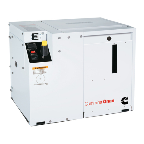
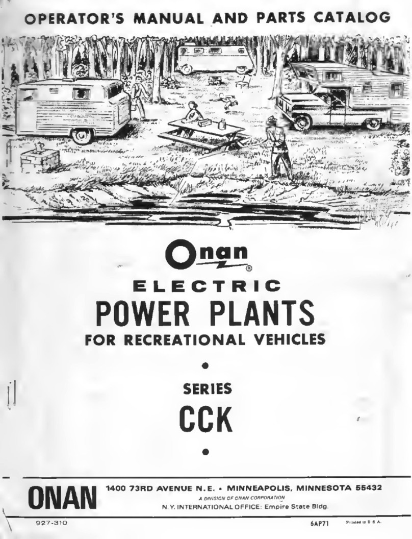
Onan BGE User manual

RV
Electric
Generating
Set
Thismanualmust
be
given
tothecustomer,
along withtheOperator’s Manual
Manual
GenSets
u
LISTED
0
Installation
965-0630
10-86
Printed
in
USA

Safety
Precautions
This
symbol
warns
of
immediate
hazards which will result in severe
personal injury or death.
This symbol refers
to
a hazard
or
-
AW*R"'G
i
unsafepractice
which
can result in
Severe personal injuryor death.
This
symbol
refers
to
a
hazard
or
*'AUT'''
j
unsafepractice which can result in
personal injury orproduct
or
property
damage.
Fuels,electrical equipment,batteries,exhaustgasesandmoving
partspresentpotentialhazardsthatcould result inserious, per-
sonalinjury.Takecareinfollowingtheserecommendedprocedures.
Do
not work on this equipment when mentally or physically
fatigued.
UseExtremeCautionNearFuel. A constantpotential explosive
or firehazardexists.
Do
not
fill
fuel tank near unitwith enginerunning.
Do
notsmoke
or use openflamenearthe unit orthe fuel tank.
Be sure all fuel supplieshavea positiveshutoffvalve.
Usea non-metallic, non-conductive,flexible section of fuel line
betweenthe generator setandstationaryfuel lineinvehicle.
LPG:
The propane fuel supply lines MUST comply with all
requirementsofNFPA501CSection3-5.paragraphs
1.1
and
1.2
as well as CanadianGas Association Bulletin 6149.2-78. The
installer must review and comply with all applicable codes
regardingfueltanks, supplylines.and pressuretestingcomplete
systemforleaksafterinstallationiscompleteandPRIOR
to
initial
operationof the generatorset
Havea fireextinguishernearby. Besureextinguisherisproperly
maintainedand be familiar with its proper use. Extinguishers
rated ABC by the NFPA are appropriate for all applications.
Consultthe local fire department for the correcttype
of
extin-
guisherfor various applications.
GuardAgainst Electric
Shock
Remove electric power before removing protective shields or
touching electrical equipment Use rubber insulative mats
placedon dry woodplatfqrmsover floors
that
aremetalor con-
crete when around electrical equipment
Do
not wear damp
clothing (particularly wet shoes)
or
allow
skin
surfaces
to
be
dampwhen handlingelectricalequipment
Jewelryisagoodconductorofelectricityandshouldberemoved
when working
on
electricalequipment
DO
NOT CONNECT GENERATOR
SET
DIRECTLY
TO
ANY
BUlLDlNGELECTRICALSYSTEM.Hazardoevoltages
can
flow
fromthegeneratorsetintotheutilityiine.Thiscreates apotential
forelectrocutionor propertydamage.
Connect
onlythroughan
approveddeviceandafterbuilding mainswitch isopen. Consult
an electrician
in
regard
to
emergency power use.
Use extremecaution when working onelectrical components.
Highvoltages causeinjuryordeath.
Follow all state and local electrical codes. Have all electrical
installationsperformedby a qualified licensed electrician.
rr
Do
Not
SmokeWhile ServicingBatteries
6
Batteries emit a highly-explosive gas that can be ignited by
electrical arcing or by smoking.
Exhaust
Gases
Are Toxic
Neversleepinthe vehiclewiththe generator set running unless
the vehicle is equipped with an operating carbon monoxide
detector.
Provide an adequate exhaust system to properly expel dis-
charged gases. Check exhaust system regularly for leaks.
Ensure that exhaustmanifoldsare secureand notwarped.
Besurethe unitis well ventilated.
Keep the UnitandSurroundingArea Clean
Removeall oil deposits. Removeall unnecessarygreaseand oil
fromtheunit.Accumula:ed greaseand
oil
cancaussoverheating
andsubsequentenginedamageandmaypresentapotentialfire
hazard.
When cleaning generatorset. providecoveror other protection
so
thatcleaningandrinsewater, andothercontaminantsarenot
allowedintothe generator. aircleaner,control box,fuelsolenoid,
or electrical connec:ors. Generator set operation and internal
components can beadverselyaffected.
Do
NOTcleanthegeneratorsetwhileunitisoperating.This can
resultin personalinjury
or
product
or
propertydamage.
Do
NOT
use high pressure air. water, or steam for cleaning
generatorsetandcompartmentDirtandotherforeignmattercan
beforced intogenerator, engineandcontrol housings.Genera-
tor set operation and internal componentscan be adversely
aff9cted.
Do
NOTuse highstrengthsolvents. They candamageelectrical
connectors.
Do
NOTstoreanythinginthegeneratorcompartmentsuchasoil
orgascans,oilyrags,chains, wooden blocksportablepropane
cylinders,etc.
A
fire couldresult orthe generatorset operation
[cooling, noise andvibration) may be adversely affected. Keep
thecompartmentfloor clean anddry.
Protect
AgainstMoving
Parts
Avoid movingpartsof the unitLoosejackets, shirts or sleeves
should not be permitted becauseof the danger of becoming
caught
in
movingparts.
Makesureallnutsandboltsaresecure. Keeppowershieldsand
guardsinposition.
If
adjustments
must
be made while the unit is running, use
extremecautionaroundhotmanifo!ds. movingparts, etc.
General
Do
not work on this equipment when mentally or physically
fatigued, orafterconsuminganyalcohol or drugthat makesthe
operationof equipmentunsafe.
RV-G.LP-4
4-
*-
,
e
Redistribution or publication of this document,
by any means, is strictly prohibited.

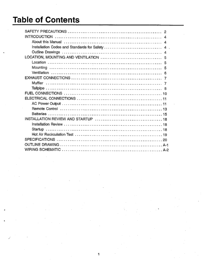
Table
of
Contents
'.
..
._
SAFETY PRECAUTIONS
................................
Inside Front Cover
INTRODUCTION
.......................................................
2
GENERALSPECIFICATIONS
...........................................
4
MOUNTING
............................................................
5
ConventionalCompartmentMount
.....................................
5
Under-Floor
Mount
..................................................
8
VENTILATION AND ACOUSTICS
.......................................
10
Ventilation
.........................................................
10
Acoustics
..........................................................
11
EXHAUSTSYSTEM
...................................................
13
General
............................................................
13
Muffler
Recommendations
...........................................
13
Exhaust Installation Guidelines
.......................................
13
Tailpipe Recommendations
..........................................
13
FUEL SYSTEM
.......................................................
16
General
.............................................................
16
Gasoline
Fuel
System
...............................................
16
ELECTRICALCONNECTIONS
.........................................
19
DC
Wiring
..........................................................
23
Pre-Start Checks
...................................................
26
Initial Start-upInspection
............................................
26
Installation Review
..................................................
28
..
Propane
(LPG)
Fuel
System
17
AC
Wiring
..........................................................
19
..........................................
INSTALLATION CHECKSAND START-UP
..............................
26
1
Redistribution or publication of this document,
by any means, is strictly prohibited.

Introduction
Each
RV
generatorset
must
be installedproperly
if
it
is
to operatereliably,quietly,and most importantly
-
safely.
Therefore,readtheentiremanual and housing/exhaust
.kit
instructions before starting the installation.
This
manual details installation procedures
for
the Onan
BGE
and BGELgeneratorsets.For operationand main-
tenance procedures, refer to the Operator’s Manual
.*
which accompanieseach
unit.
Listed
and certified,
this
generatorsetmeetsorexceeds
all requirements of the National ElectricalCode,Article
551
(NFPA
70)
as
well
asANSI/RVIA Standard EGS-1.
UL
Standard 1248,and CSA
Bulletin
946. Recreational
vehicleinstallationsMUST comply
with
thesespecifica-
tions aswell asANSI 11
9.2,
Standardfor Recreational
Vehicles. The recreational vehicle manufacturer and
generatorsetinstaller
MUST
alsocomply
with
anylocal
codes such as CaliforniaAdministrativeCode
Title
25,
which pertainsto the generatorset installation.
UL
listing
and
CSA
certification
applies
to60
Hz
models
only.
Requirements
fo
be considered prior to the installation
are
listed
below. Each
is
covered
in
thefollowingtext
or
associated
kit
instructions.
0
Level and supportive mounting surface.
0
Adequate cooling
air.
0
Discharge
of
circulatedair.
0
Discharge
of
exhaust gases.
0
Electrical connections.
0
Fuel installation.
0
Accessibilityfor maintenanceand service.
0
Noise levels.
The
following
list
of installation codes and safe.,
recommendationspertainstotheinstallation
and
opera-
tion
of
this
RV
generator set. The address of each
agency
is
listed
so
that
you
can obtain a copy
for
your
own use.
‘
INSTALLATION
CODES
AND
SAFETY
RECOMMENDATIONS
I
i
1.
ANSI-Al19.2 Recreational
Veh.
ANSI/RVIA-EGS-1
Industry
Assoc.
14650
Lee Road
Chantilla
VA
22021
2.
NFPA
70
(N.E.C.)
National Fire
470
Atlantic Ave.
Boston
MA
0221
0
NFPA-501
C
Protection Assoc.
3.
CSA Electrical Canadian Standards
Bulletin
#946
Assoc.
-
Housing
&
Const. Materials Section
178
Rexdale
Blvd.
Rexdale
Ont.
Canada
M9W
1
R3
4.
UL
Standard
1248
Underwriters
Lab
Inc.
333
Pfingsten
Road
Northbrook
IL
60062
5.
California Stateof California
Administrative DocumentsSection
Code
-
Title 25
Chapter
3
North Highlands
CA
P.O.
Box
101
5
95660
I
AWARNING
I
Incorrect installation, service,
or
replacement of parts can result
in
severe
personal injury and/or equipmentdamage. Servicepersonnel must be qualified
to perform electrical
and
mechanicalcomponentinstallation.
2
Redistribution or publication of this document,
by any means, is strictly prohibited.
'.
.*
._
BGE
GOVERNOR
SPARK ADJUSTMENTS
SUMMER/WINTER
CARGURETOR ADJUSTMENT
ADJUSTMENTS
FUELPUMPINLET
AC CIRCUITBREAKERS
REMOTESTART
CABLECONNECTION
LOCATIONOP~ONAL
SPARK
BGEL
PLUG
VAPORIZER
\\
ADJUSTMENTS
AC CIRCUITBREAKER
FUELFILTERAND
SOLENOIDASSEMBLY
NEGATIVE
(-)
BA'K
CABLECONNECTl POSITIVE
(+)
BATTERY
TO
PLATE CABLECONNECTION
LOCATIONOPTIONAL REMOTESTART
CABLECONNECTION
.
M-1604-1
FIGURE
1.
BGEAND BGEL GENERATOR
SETS
3
Redistribution or publication of this document,
by any means, is strictly prohibited.
General
Specifications
.-
ENGINE
Onan opposed2-cylinder,4-cycle,air-cooled,gasoline-fueled forthe
BGE
model
and propane-fueled for
the
BGEL
model. Remotestart,negative ground,12-volt,
automotive-type
starter.
'
GENERATOR
Onan-built,four-pole,revolving field,permanentlyaligned
to
engine.
Frequency
.......................
-50
Hz..
........................
60
Hz
'Watts..
..........................
.3500
............................
4000
Volts..
....................
.11.0/220
or
1201240..
....................
120
Amps..
..................
.31.8/15.9
or 29.2114.6..
..................
.33.3
Phase
..............................
10
.............................
.10
c
.
..
CONTROL
Front-mountedcontrolfeaturesfixed battery charger
and
remote
start
capability.
.
GENERATOR
SET
Dimensions*
..
Height
..............
:.
................................
14.0
in.
(356
mm)
Length..
..............................................
25.0
in.
(635
mm)
Width..
...............................................
18.8
in.
(478
mm)
60
Hz.
...................................................
218 Ib (99
kg)
SO
Hz..
..................................................
228
Ib
(104
kg)
60
Hz
.........................................
-480
ft3/min
(1
3.6
m3/min)
50
Hz
.........................................
.400 ft3/min
(1
1.3m3/min)
BGE
...
1
.............................................
1
/4
in.
barbfitting
BGEL..
..................................................
-1
/4
in.
NPTF
Battery Voltage
..................................................
.12 volts
Recommended Battery Capacity'.
................
.360 cold cranking amperes
Cranking Current
.............................................
100
amperes
rlmin
at:
60 Hertz
..........................................................
7800
50
Hertz
.........................................................
1500
Weight
Air
Requirements:
Fuel
Inlet Connection
*Under-Floormountgeneratorsetwith compartment
housing
has
slightlylarger
dimensions.
See
Mounting
section.
Redistribution or publication of this document,
by any means, is strictly prohibited.
Mounting
Read the entire manual and housing/exhaust kit
instructions before installingthe generator set The
generatorsetisdesignedfortwovery differenttypes
of
installations;conventionalcompartmentmountinstalla:
tions and under-floor mount installations. Choosethe
appropriatesectiondescribingeach and carefully fol-
lowthe instructionsgiven.
CONVENTIONAL
COMPARTMENT
MOUNT
Ina conventional installationthe generator set isactu-
ally installedon aframeworkthat ispart of the recrea-
tionalvehicle
(RV).
Thisframeworkmustbeconstructed
inaccordancewiththe safety-approvedspecifications
contained inthe following CompartmentConstruction
section..
Unlessgeneratorset
is
toberemovedfromunderneath,
plan the locationfor an access opening to be large
enough
to
permitset removal. Allow additional clear-
ance for easy access
to
the oil fill, drain, filter and oil
dipstick as well as the air cleaner element, circuit
breaker,governoradjustments,carburetoradjustments,
Start/Stop switch, and DCfuse. The locations of each
are shown in Figure
1.
Designthecompartmentlargeenoughforthegenerator
set, with
0.6
inch
(15
mm)
minimumclearancebetween
the generator set and compartment walls and ceiling
(andacousticalmaterial,if used). See Figures
2
and
3.
Compartment
Construction
1.
Installthe generator set
in
its own compartment.
Separatethecompartmentareafromthelivingquar-
tersandanyfuelsupply(gasoline
or
propane)witha
vapor-tight wall. See Figures
2
and
3
for minimum
clearancesand compartmentsize.
2.
Linethecompartmentwallswith26-gaugegalvan-
izedsteel
or
amaterialofcomparablestrength,dur-
ability andfire resistance (see NFPA
70, NEC
and
CaliforniaTitle
25
for
completedetails).
3.
Constructthecompartmentfloor inamanner
so
as
to prevent oil, fuel or water accumulation. Com-
partment drainage can be accomplished
by
1
/2
inch
(13
mm)
diameterholesasshown
on
thecom-
partmentfloordrawings, Figure
3.
Fire presents the hazard of
*
jaWAR"G1
severepersonalinjury or death.
To
prevent a fire hazard,
do
not position the
muif/er directlybelow
a
drain
hole.
Do
NOT
useabsorbentsoundproofingmaterialon
compartmentfloor. The floor should have minimal
openingsto reducesound level.
4.
Equipbasewith an oil drain holeto the outsideof
compartment.
Do
not mountthe muffler belowthe
oil drainvalve.
Exhaustgases present the haz-
ard of severepersonal injury or
death. Make thecomparfmentwallsvapor-tightto
theinteriorof thevehicletopreventexhaustfumes
fromentering ihe vehicle coach.
5.
Securethegeneratorsetmountingplatetosupport
frameusing
318-1
E
UNC,
grade
5
screws.Theback
two mountingholesaresuppliedwith weld nutsto
facilitateinstallingscrews.Thefront
two
holescan
be secured with 318-1
6
screws, lockwashersand
nuts. The front holes are square to allow use of
3/8-16 cage nutsif desired.
See
Figure
3.
1-1
Road vibrationscan causecom-
ponent damage
to
generator set
if unit mounting plate is not fastened securely
to
vehicle compartment, Use screws
of
sufficient
length
to
allow a minimum of
1-1f2
threads
to
extend through nut
to
ensure maximum holding
power.
5
Redistribution or publication of this document,
by any means, is strictly prohibited.
;E,
ym
&::
OIL FILTER REMOVAL
*-AIR FILTER
FUELINLET
-
114
INCH
1317.0
1
DISCHARGE
(
OPTIONAL
EXHAUST OUTLET
NOTES:
1.
DIMENSIONING INCLUDES
0.6
INCH
(15
mm)
MINIMUM CLEARANCEREQUIRED
BEMlEENSETANDlNSUIATlONORCOM-
PARTMENTWALLS.
IMUMSHOWN. ALLOW
EXTRA
SPACEAT
OIL
FILL SIDE AND EQUALLY ON BOTH
ENDS.
3.
ALLOW MINIMUM
OF
0.6
INCH
(15
mm)
CLEARANCEBETWEENTOP
OF
SET
AND
INSULATlON
OR
COMPARTMENT
CEILING. MINIMUMHEIGHT
14.60
INCHES.
4.
WEIGHT
-
218
LBS.
(99
kg).
50
Hz-228
5.
DIMENSIONS
IN
(
)
INMILLIMETRES.
2.
IF
COMPARTMENT
IS
LARGERTHANMIN-
Lb1104
kg.
I
OIL
DRAIN VALVE
FOL
.62
1.0.
HOSE
“L
FUEL
INLET
\
0
25
nos€
¶4RB
ALT FUEL
PUMP
.75
INCHCONDUITWITH
AC. PIGTAILS
36.0
INCHES
(0.92
m)
LONG
VIEW
A-A
500-2126
FIGURE
2.
BGElBGEL COMPARTMENT MOUNT OUTLINE (BGE SHOWN)
6
Redistribution or publication of this document,
by any means, is strictly prohibited.

X
19.75
(501.6)
I
so
sa.
HOLE
(127)
2
PLACES
NOTES.
CONVENTIONALCOMPARTMENT
MOUNT
BGE-BGEL
WlTH
END-MOUNTEDMUFFLER
CUT-OUT
FOR
COOLING
1.
DIMENSIONS INCLUDE
0.6
INCH
(15
mm)
AIR DISCHARGE MINIMUM CLEARANCE REQUIRED
BETWEENSETANDiNSUWTlON
OR
COM-
PARTMENTWALLS.
IMUMSHOWN. ALLOW EXTMSPACE AT
OIL FILLSIDES AND EQUALLY ON
BOTH
ENDS.
3.
ALLOW MINIMUM
OF
0.6
INCH
(15
mm)
CLEARANCEBETWEENTOPOF
SET
AND
ING.
MlNiMUMHEIGHT-
14.60
INCHES(371
mm).
.
2.
IFCOMPARTMENTISLARGERMANMIN-
INSULATION
OR
COMPASTMENT CEIL-
4.
DIMEF.!SIDNS
(
]ARE
IN
MILUMETRES.
5.
SWAREHOLES
(5.5il/127)
ARESUITABLE
FOR
USE
OF
38
IWCH
CASE
MU.
.JOBDRAINHOLE
(127)
2
PLACES
FIGURE
3.
COMPARTMENT
FLOOR
PLAN
.
7
Redistribution or publication of this document,
by any means, is strictly prohibited.
UNDER-FLOOR
MOUNT
Foran under-floormountinstallation,thegeneratorset
ismountedinahousingbelowthefloorandoutsidethe
coachof therecreationalvehicle.Thishousingassem-
bly should be as supplied
or
approved by Onan, and
must be installedin accordancewith safety approved
specifications. Review the following text for general
applicationinformation,andreviewtheproperhousing/
exhaust kit instructionsfor further specificsregarding
under-floormountinstallations.
The vehicle constructionmust be ableto supportthe
weight
of
thegeneratorset (seeGeneralSpecifications).
It is the vehicle manufacturer’s and the installer’s
responsibilitytoprovideandassure
a
structurallysound
supportframe, by usingtubing, anglebrackets, or with
steel reinforced plywood
or
other compositionboard.
Reinforcementof plywood
or
particleboardcanbewith
3
inch
(76
mm)
or
largerwashers
or
afull metalplate.
.-
General
Generator SetLocation:
Whenchoosingalocationfor
mountingtheunder-floormountgeneratorset,consider
thefollowingnotonlyformounting,butforprotection
of
the generatorset as well.
Figure
4
showsthe mostcommonmountingareas of a
RV
generatorsetinarecreationalvehicle.
If
thegenera-
tor set is mounted
on
the curb side, location
l
or
2,
protectthegeneratorendofthegeneratorsetfromroad
splashanddebris.
If
mountedonthedriver’sside,
loca-
tion
3
or
4,
protect the engine end of the generator.
(Installationshouldbeverifiedbyaroadtestinmudand
slush). Referto shadedareasof Figure
4.
Leave an area between the generator set and the
recreationalvehicleskirtfor anair inlet if
it
is notsub-
jected to road splash. See
V€NTlLATlON
for more
detailedinformation.
Air
inlet openings
to
thegeneratorsetcompartment must notallow
dirt, rock, water, orslushtodirectly hit the generator
set.
Oustand
saltentrance into the compartment must
be
minimized. Payspecial
attentiontoprotection
of
thegenerator, control, choke,andgovernor
Access Opening:
Provide an access opening
og
the
side of the recreationalvehicle for the generator set.
Makeitlargeenoughtoallowforchecking
or
addingoil,
foradjustinggovernorandcarburetor,andforaccessto
the control paneland
AC
circuit breaker.The opening
shouldalsoprovideaccessfor oilandairfilter replace-
ment
so
that the generator set does not have to be
lowered for these procedures. See Figure
1
for
locations.
Mounting Clearance:
Ifthecompartmentdoordoesnot
.
openthefullwidthofthegeneratorsetandtothebottom
of thevehicleskirt, provide
2
inches
(51
mm) minimum
betweenthetrayandtheskirtoftherecreationalvehicle.
Thisdistanceallowsloweringthegenerator setwithout
hittingthe vehicle skirt. Figure
5
shows basicdimen-
sions
of
the under-floormount generator set.
8
Y
Housing Assembly
Therecreationalvehiclemustbeadaptedfortheunder-
floor housing.Theconstructionofthevehiclemustsup-
port the weight of the generator set. It is the vehicle
manufacturer‘sresponsibilityto provide a structurally
soundframe and carriagebolts
or
equal to attachthe
housingkit.
failure to meet Onan approval for
modifications
of
housing kits or for
non-Onan kit housing installationsmay void intent
of
ULKSA
approval. Liability for damage or injury and
warranty expenses
becomes
the responsibility of
the
person making themodifications.
Use template suppliedwith housing kit to insurethat
panels are installed square to each other. Failureto
mountpanelssquaremayresultinsparkplugbreakage.
Reviewthe exhaustsystem kit installationinstructions
andcomponentparts. Planclearancesformovementor
removalof exhaustcomponentswhen generatorsetis
loweredfor inspection/maintenancepurposes.
areas.
Baffi&
might berequired
to
protectcertain areas.
~
REFER
TO
INSTRUCTIONS
EXHAUST
KIT
INSTRUCTIONS
FIGURE
4.
COMMON
MOUNTING
AREAS
OF
GENERATOR
s
Redistribution or publication of this document,
by any means, is strictly prohibited.
OIL
FILL AM0
CHECK
r
8
NOTES
ALT
NELPUMP
1.
DIMENSIONS INCLUDE
0.E
INCH
(15
mm)
MIN REQUIRED CLEAWNSE BETWEEN
MENTWALLS.
2.
IF
COMPARTMENT
IS
LARGER THAN MIN
SHOWN.
ALLOW
!EXTRA
SPACE AT OIL
FILL
SIDE
AND
EQUALLYON BOTH
ENDS.
Lb1104
kg.
SET AND INSULATION
OR
COMPART-
NEL
$NET
m
2:
WE
8410
3.
WEIGHT
213
LB
(93
kg)
50
Hz-228
4.
DIMENSIONS
IN
(
)
ARE
IN
mm.
.75
INCHCONDUITWITH
AC. PIGTAILS
36.0
INCHES
A.C.
CIRCUIT
BREAKERS
RU.a
159LOl
YIN
CLCkUNCC
rOR
UIT
5WW
.
'\
VIEW
A-A
'w
500-2135
FIGURE
5.
UNDER-FLOOR
MOUNT
BGEIBGEL(BGE
SHOWN)
9
Redistribution or publication of this document,
by any means, is strictly prohibited.

Ventilation
and
Acoustics
VENTILATION
The most importantfactors
of
ventilationfor an
RV
air-
cooled generator set are sufficient incoming air (for
combustionand cooling) and adequateexhausting of
heatedair.
All
Onangeneratorsetsforrecreationalveh-
icles
useVacu-Flo@cooling.
Acentrifugalfan inascrollhousingontheengine(Fig-
ure
6)
drawsairfromthegenerator endof thecompart-
ment,throughthegenerator(generatoralsohasacool-
ing fan), and over the cooling surfaces of the engine,
thendischargesthe heated air outthrough theVacu-
Floe
dischargeopening.
Make sure nothing obstructs or restricts discharged
airflowandthatrecirculation
of
airisminimal.
A
dustor
noisedeflector
if
added mustbeaminimumof
6
inches
(150
mm) belowthe generatorset and open on three
sides.
Exhaust gas presenfsthe hazard
of
(BWARNINGI
severe personal injury
or
death.
Since discharged cooling air can contain some
exhaust gas, never use discharged cooling air for
heating.
Thefree airinletareaiscritical
for
propergenerator set
operation and cooling.
A
minimumfree air inletarea of
85
in2
(548
cm2)with no restrictionsisrequired. Refer-
ence: thegenerator set airdischargerateis
480
ft3/min
(1
3.6
m3/min).
-
FIGURE
6.
VACU-FLO@
COOLING
SYSTEM
Whenplanningtheairinlettothegeneratorset,allowfor
airflow restrictions caused by grilles and duct work.
Some expanded metal grillesprovideonly
60
percent
freeairinletareapersquarefoot. Eventhemostefficient
grilleonlyprovidesabout
90
percentfreeinletareaper
squarefoot The free inletarea of the materialcan be
obtainedfrom the material supplier. Multiplythe grille
area times thepercent
of
free area
of
thegrillto obtain
thefree inletarea.
Inletairductingshouldprovideadirectfree-airflowpath
togeneratorset,withminimalbends;andmaterialsused
shouldbesmoothand non-restrictiveto airflow.
Air inletopeningsshouldbelocatedas highaspossible
to allow for convection coolingof heatedair from the
generator set compartmentafter unitshutdown.Other-
wise, hard starting might result due to vapor locking
(gasolinefuel), hotcombustionair, etc.
Fuel or fuel leakage presents the
IBWAR”G1
hazardoffire
or
explosionwhichcan
causeseverepersonalinjuryor death. The ventilation
system shouldprovide a constant flowofair
to
expel
anyaccumulation offuelvapor. Compartmentsmust
be
vapor-tight to the vehicle interior
to
keep fumes
fromentering the vehicle.
To
obtainthe
85
in2
(548
cm2) freeair inletarea, Onan
recommendsbringingincoolingairthtoughtherecrea-
tionalvehicleskirt. This canbeaccomplishedbyusing
theaccessdoor,ductingintothegeneratorendfromthe
side wall, or using the horizontal area between the
recreationalvehicleskirt and the generatorset along
withtheverticalarea(if roadsplash
is
notaproblem
-
seetheMOUNTINGsection).SeeFigure7forreference
totheseareas. Iftheskirtofthevehicledoes notextend
toorbelowthe
top
ofthegeneratorsetdriptray,provide
an extension.
You
can bring air from under the coach for cooling.
However,runtestswhiletherecreationalvehicle
is
both
parked and while the vehicle is moving at highway
speedsto ensure proper cooling with this method.
A
temperature rise of
8°F
(4.4OC)
between the outside
ambient and
air
in
the top openings of the generator
housing
is
acceptable.
I
..
..
,
b
..
10
Redistribution or publication of this document,
by any means, is strictly prohibited.

I
I
Duct
MINIMUMFREEAIRFLOWTO
GENERATOR
SET
COMPARTMENT
(MAY
BE
CUMULATIVE):
85
IN2
(548
cmt)
Skirt
RV
Floor7
1
,Skirt
Air
In
AIR INLET ACCESS DUCTFROM
BETWEEN
RV
SKIRT
Air
Out
DOORAIR SIDEWALL
AND
GENERATOR
SET
INLET
TO
GENERATOR
FIGURE
7.
AIR
INLET
ALTERNATIVES
FOR
UNDER-FLOOR
,
MOUNT
GENERATOR
SET.
ACOUSTICS
The Onanhousingkitfortheunder-floormountgenera-
tor set containsacoustical materialto minimizenoise.
Additionalinsulationisnot necessary. If, however,you
are constructing your own compartment or housing,
usethefollowingguidelines.
Forthe conventionalcompartmentmount, if compart-
ment penetratesfloor, besure alljointsand comersof
the compartmentare vapor-tightto the interior. Lining
the compartmentis less effectiveif openings, cracks,
doors,andjointsarenotsealed.Also,sealcompartment
door edge to eliminate noise leaks around the door
perimeter.
Coverthesoundreflectivesurfaces,back,topandsides
(not compartment base) with fiberglassor other self-
extinguishing acoustical material. Acoustical material
and adhesiveshouldberatedfor useat
2OOOF
(90°C)
minimum.
Ratherthan usingonesinglematerial,
a
combination
of
materialscan reducenoiseconsiderably. Forinstance,
a sheet of lead or viscoelastic materialand a layer of
acousticalmaterialsismoreeffectivethaneitheralone.
To reduce line of sight noise, a sound panel (baffle)
shouldbeaddedbehindtheairinlet. Thepanelmustbe
spaced
to
allowfor minimumfreeairinlet
of
85
in2
(548
cm2).
RefertoFigure
8
toaidyourgeneratorsetcompartment
design and noise reduction plans. Size ducting to
ensurethat minimumfreeairflowof
85
in2
(548
em*) is
still attainedafter acousticalmaterial isadded.
High
temperatures in the compart-
l3iE@@I
ment
can
present the hazard
of
fire
which
canresulfinseverepersonal injury
or
death.
To
meet
UL,
ANSl
and
CSA
femperafureriserequirements
for
recreational vehicles, insulafion
must
not
reduce
fhe
0.6
inch
(15
mm)
clearance specified.
11
Redistribution or publication of this document,
by any means, is strictly prohibited.

12
Redistribution or publication of this document,
by any means, is strictly prohibited.

Exhaust
System
GENERAL
Plan eachindividual exhaustsystemcarefully.
A
proper
installation
is
not
only
vapor-tight,
but
usually quieter
and safertoo.Be sureto checkall applicablestandards,
local codesand regulations.
Refer to the following
text
for recommendationsto fol-
low when installing the exhaust system.Then refer
to
the installation instructions supplied
with
the exhaust
system
kit
for
specific mounting procedures.%ee
Fig-
ures
9
and
10
for
exhaust
kit
options.
..
.-
MUFFLER RECOMMENDATIONS
Onan supplied mufflerisparkarresters are
forest
ser-
vice approved and meet coderequirements.(Failure
to
provideand maintain asparkarrestercan be
in
violation
of
the
law.)
Use
only
ONAN
UL/CSA tested
mufflers.
Liability for damage or
injury
and warranty expenses
duetouse
of
unapprovedmufflers
or
installationmodifi-
cationsbecomes
the
responsibilityof theperson instal-
ling
substitute
muffler
or
performing the modifications.
Contactan Onan distributorfor approvedexhaustsys-
tem parts and installation instructions.
EXHAUST INSTALLATION
GUl
DELlN
ES
Theexhaustsystem
must
be no closerthan
3
inches
(76
mm)
from combustible material (wood,
felt,
cotton,
organic fibers, etc.),
or
be
so
located, insulated
or
shielded,that
it
does not raise the temperature of any
combustiblematerialmorethan
117OF
(65OC)abovethe
ambient air inlet temperature.
The
exhaust
system
must
extend a
minimum
1
inch
(25
mm)
beyondtheperimeterof
the
vehicle.
If
thegenerator
set tailpipe
is
on the same
side
of the coach asthe
compartment.
try
to
terminate the tailpipe aft of
the
generator set air intake to reduce the
possibility
of
exhaust recirculation,
by
directing
the
exhaust down
and to the rear.
Exhaust gas presents the hazard of
severepersonal injury
or
death. Use
only Onanspecifiedexhaustequipment withgenerator
setand supportthesystemper
kit
instructions.
Exhaustgas presents thehazardof
iAWARNiNG
1
severepersonal inibry or death.
Do
notterminateexhaustgasunder vehicle.
Do
nottermi-
nateexhaustsystemdirectly under any vent, window,
or opening which can be opened and which is not
pennanenilysealedfromthevehiclelivingspace. Keep
allopeningsclosedwhenthegeneratorsetisrunning.
Excessive exhaust back
pressure
cancauseenginedamage. If tai/pipe
deflector is
used,
makesureitislargeenougbtopre-
vent backpressure.
Water vapor cancauseenginedam-
-/
age. Do notconnectthegeneratorset
exhaust to the vehicle exhaust.system since water
vapor from one enginecandamagethe other.
TAILPIPE RECOMMENDATIONS
An
exhausttailpipe
is
NOT
supplied because of varia-
tion
in
lengthrequirementsbetween motor homemanu-
facturers.After muffler
is
installed and
prior
to installing
exhaust tailpipe, refer to
the
following recommenda-
tions
for additional
tips
and safetyconsiderations.
Use
1-318
inch
I.D.
18
gauge
rigid
steel
tubing
for
tailpipe.
I
Exhaustgas presents the hazard
oi
~AWARNING
severepersonal injury or death.
Do
not use flexible exhaust tailpipe since it can leak or
break dueto roadshock or vibration.
Do
notterminate
exhaust sysiem under the vehicle. Direct exhaust
gases away from any window, door, or compartment
openings.
Do
notoperatethegenerator set withoutan
exhausttailpipe.
Use U-bolt type automotive muffler clamps marked
1
-
318
and double rubber, U-shaped shock
mounted
hangers for supporting the exhaust system.
If
tailpipe
extendsbeyond
1-1
/2
feet
(0.46
m)
from muffler.attach
an automotive tailpipe hanger for additional support
The exhaustsystemshould be supportedat or nearthe
perimeter ofthe vehicleto prevent the pipe from being
damaged and pushed
up
under the
skirt.
Angularmounting of muifierand tail-
exhaust system damage. Properly mounted hanger
brackets wili absorb much road
shock
vibration and
prolongtheusefulnessofexhaustsystemcomponents.
Mount muffler and iailpipe hanger brackets directly
abovethecomponentsupported,notatanangle.
Do
not
twist therubbersectionsof any hangers.
:
igCAUT'oN
pipe hanger brackets can result in
13
Redistribution or publication of this document,
by any means, is strictly prohibited.
..
HANGER
BRACKET
(3
FOOTll
METRE
FROMDOWNPIPE.
OR
AT
PERIMETER
OF
VEHICLB
.
..
EXHAUST
ACCESSORY
KIT
542-0471
SHOWN
us-1146
EXS1147
f
IGURE
9.
EXHAUST
SYSTEM
KK
EXAMPLES
FOR
CONVENTIONAL
COMPARTMENTMOUNT GENERATOR
SET
14
Redistribution or publication of this document,
by any means, is strictly prohibited.

EXHAUST
ACCESSORY
KIT
542-0482
SHOWN
TAILPIPE
NOT
FURNISHED
BY
ONAN
EXHAUSTACCESSORY
KIT
542-0469
SHOWN
EXHAUSTACCESSORY
KIT
542-0470
SHOWN
Exs-1149
TAILPIPE
NOT
%--
FURNISHED
BY
ONAN
FIGURE
10.
EXHAUST
SYSTEM
KIT
EXAMPLES
FOR UNDER-FLOOR
MOUNT
15
Redistribution or publication of this document,
by any means, is strictly prohibited.
Fuel
System
Model
60
Hz
50
Hz
GENERAL
This
installation manual covers gasoline and
LPG
(liquid-propane gas)
fuel
systems.
The
Onan
BGE
model
is
gasoline-fueled,and
the
Onan
BGEL
model
is
liquid
LPG
fueled. Separate procedures are given for
each.
No
Load
Half
Load
Full
Load
0-4
gallhr
0.6
gal/hr
0.8
gallhr
(1.5
Ilhr)
(2.3
I/hr)
(3.0
Ilhr)
0.35
gal/hr
0.53
gallhr
0.73
gal/hr
(1.3
Ilhr)
(2.0
Ilhr)
(2.8
Ilhr)
*
b.
Fuel presents the hazard of fire
or
explosionwhichcanresultin severe
personal injury or death.
Do
not smoke or allow any
ignition sources in the installation area. Keep a type
ABC
fireextinguishernearby. Theventilationsystemof
theinstallationareamustprovideaconstantflowof air
toexpelanyaccumulationof fuel vaporwhilethevehi-
cleis intransit. Compartmentsmust be vapor tight to
fhevehicleinterior topreventanyfumes fromentering
the vehicleinterior.
GASOLINE
FUEL
SYSTEM
.
Fuel System Provisions
Generatorsetinstallationsmay
be
designedtosharethe
vehicle fuel
supply
tank
with
the vehicle
engine.
AI1
connections to the vehicle
fuel
tank
must
be done
in
accordance with chassis
(vehicle)
manufacturer's
detailed installation instructions. See Fuel
Line
In-
stallation.
The generator set includes a
fuel
shut-off valve as a
safety feature and
is
an integral part of
the
fuel
pump.
Should
the
vehicle fueltank become pressurized,
the
positivefuel shut-off
prevents
floodingof
the
generator
set
when
the
set
is
not operating.
Forlhe possibility
of
contaminatedfuel,Onanrecommendsanin-line
luel filter.
.
Recommended Fuel
Use clean,fresh, unleaded or regular grade gasoline.
Using
unleaded gasoline
results
in
extended periods
between service, longer spark
plug
life,
and
reduced
carbon.clean-out maintenance.
If
regular gasoline
is
used,lead deposits
must
be
removed from
the
cylinder
heads as required
to
'alleviate engine power loss.
Unleaded gasolinemay
be
safely
used
after
lead depos-
its
have been removed.
.
.
Do
not alternate between leaded
k&%!@l
(regular) and unleaded gasoline.
Lead deposits can cause engine damage if
not
removedbefore usingunleadedgasoline.
Fuel Consumption
It
should be noted that
under
varying
electrical loads,
fuel
consumption of
engines
for recreational vehicle
generator
sets
variesaccordingly.
Fuel
Line
Installation
Recreationalvehicle
fuel systems
aredesignedto oper-
ate
in
a
criticalpressure range.It
is
very
important
dur-
ing
the installation
of
the
generatorsetthat
the
vehicle
fuel
supply
design
NOT
be
altered.
The
fuel
fill
tube,
fill
limitervent, vapor canister,vapor
lines
and gas
fill
cap
should
never
be changed,removed or replaced
without
PRIOR
approval
from
thevehicle manufacturer. Check
thefiller
cap
to
ensure
thatthe
pressure
vacuum
relief
valve
is
functioningproperly.Replace
if
required.
If
separateconnection
is
not suppliedforthegenerator,
addasecondfuelpickup inthetank.Thispickupshould
not
extend
belowthebottom
1
/4
of tank
so
thevehicle
can
still
be
run,
after generator
runs
out of fuel.
.
Do
NOTtee
off
thevehiclefuel
line,
doing
so
may cause
poor operation of thegenerator or
the
vehicle. Consult
with
vehicle manufacturerforfurtherspecificsregard-
ing
asharedfuel
supply.
Unauthorizedfuelsystemmod-
ifications could
result
in
dangerous operating con-
ditions.
ACA~ON
Connecfingfhegeneratorsetfuelline
a
with
a
fee
to
the
main fuel.line
can
resun
in
fhe
generafor set starving for fuel when
ihe
vehicle
is
operatedat highway
speeds.
Thegenerafor
setfuelpumphasneitherthe
capacity
nor thepower to
overcomefhe
draw
ofthevehicleenginefuelpump. Use
a
separafe
fuel
line
for
thegeneraforset.
Gasolinepresentsthehazardofexplo-
[-I
sion
or
firewhich
can
resulf insevere
personalinjuryordeath.
Do
not connectthegenerator
setfuel line tothepressurizedpart of thevehiclefuel
system.
Flooding
of
thegeneratorsetengineand
com-
partmenf
can
occur,resulfingina firehazard.
tnstall
an
approved,
flexible
non-metallic (non-
conductive)andnon-organicfuel
line
betweenthe
veh-
ickfuel
system
and thegenerator
set
to
absorbvibra-
tion.
Onan recommends using
a
seamlesssteeltubing
and flared connectionsfor long
runs
between
the
fuel
tank
and
the
flexible
connectorto
the
generatorset.
Run
fuel
linesatthe
same
height asthetop
level
of tank
toa point asclosetothe
engine
aspossible.
This
redu-
cesthedangeroffuelsiphoningoutofthetankiftheline
should break.
.
16
Redistribution or publication of this document,
by any means, is strictly prohibited.

Keep fuel linesawayfrom hot
engine
or exhaustareas.
This
reduces chance
of
vaporlock. Install lines
so
that
they are accessible and protected from damage. Use
metal strapswithout sharp edges
to
securethem.
No
&ad
Half
Load
0.5
gal/hr
0.8
gal/hr
(1.9
I/hr)
(3.0
Vhr)
Flexible
line
must
be
long
enough to allow for set
movement
in
order to prevent
binding,
stretching
or
breaking.
PROPANE
(LPG)
FUEL
SYSTEM
(60
Hz
Only)
+-
Fuel
System
Provisions
'
.-
.
Onan
liquid
LPG
generatorsetscontain afiltercartridge
and magnet
in
the fuel solenoid valve to protect
the
solenoid valve and regulator valves from
dirt
and con-
taminants. The solenoid valve and
filter
is
shown
in
Figure
11.
Figure
12
shows the flow
diagram
for
the
liquid
LPG
fuelsystem components
used
on thegenera-
tor
set
Full
Load
1.3 gal/hr
(4.0
I/hr)
Generatorsetoperation
using
liquid
LPG
is
very
sensi-
tiveto altitude,temperature,and
BTU
contentof
the
gas.
Variation
in
any oneof thesefactorsdirectlyaffectsthe
performanceof thegenerator
set.
Becauseof
this,
minor
adjustments
might
be
required
after the installation,
refertoGeneratorSetService
Manual
if
adjustmentsare
required.
.,
Recommended
Fuel
Use clean,fresh commercial propane or
HD-5
grade
liquid
propane gas
in
a
mixture
of
at
least
90
percent
propane.Propane
fuels
otherthan
HD-5
gradecancon-
tain morethan
2.5
percentbutaneand can
result
in
poor
fuel vaporization
and
poor
engine
starting
in
low
ambienttemperatures(below32°For
OOC).
Fuel Consumption
It
should
be
noted that under varying electrical loads,
fuel consumption of engines for recreational vehicle
generator set varies accordingly. Average fuel con-
sumption
at
various loads
is
shown
in
thetable below.
LPG
FUEL
CONSUMPTION
Propane Fuel
Lines
and
Supply
Tank
.
The installer
must
review
all
codes that apply to the
particularinstallation.Paragraph
3-5.1
(Gas
Piping
Sys-
tems)
of
NFPA
Pamphlet
501C
deals specifically
with
propanefuel
linesbutdoesnotnecessady
coverallapplicable
codes and regulations. You
can
obtain this
pamphlet
from
the
address
listed
in
thebeginning of
this
manual.
When
installing
the fuel
lines,
keep the following
in
mind:
1.
Install all propanefuel
lines
so
they areaccessible,
yet
protected
from
damage.
2.
3.
4.
FUEL
FILTER
BODY
FIGURE
11.
FUEL
SOLENOlO
VALVE
AND
FILTER
Use
metal
straps
withoutsharpedgesto securefuel
lines.
Keep
fuel
lines
away from hot engine or exhaust
areas.
Do
NOT
run
fuel
lines
in
conjunction
with
electrical
wiring.
Most propane
(LPG)
liquid
withdrawal generator set
installationsaredesignedto sharethevehiclepropane
fuel
supplytank(s).
The
vehicle
propanefuel
supply
tank
MUST
have a dip tubeto
ensure
liquid
withdrawal.
An
excess
flow
valve
MUST
be
mounted internal
to
the
propane
fuel
supplytank(s)
per
NFPA
501
C,
Paragraph
3-4.4.
This
excess
flow
valve
and propane fuel lines
MUST besized
so
the
excess
flow
valve
will
close
with
a
completely
severed
(broken)propane fuel line. For
operation at the lowest ambient temperature, a valve
rated at
2.6
gallonsper hour
(9.9
Vhr)
flow rateand
6.5
pounds
per
square
inch
(45
kPa)differential
pressure
is
recommended. Consultthe
Natural
LP GasAssociation
for
the
limitationsof excess
flow
valves.
17
Redistribution or publication of this document,
by any means, is strictly prohibited.
Install an approved flexible non-metallic (non-
conductive)andnon-organicfuel linebetweentheveh-
iclefuel system andthe generatorset to absorbvibra-
tion.Onan recommends usinga seamless steel tubing
and flared connection
for
long runs between the fuel
tankandtheflexible connectorto the generator set.
aldotIurV~~)
Mu3
confonn
to
ASME
or doland
CTC
slandards. (Working pressure
A
manualshut-0%valve MUSTbemountedonthepro-
panefuelsupplytank.Thissupplytankvalve
MUST
be
fully open when operatingthe generatorset
to
ensure
theexcessflowvalve
will
closewithasevered(broken)
propanefuel line.
Must
Close
with
Completeline
Breakage.ConsultNational
LP
Gas
AssocialionPublication
113-78
For Limitations.
VblQZ
.-A
hydrostatic pressure relief valve MUST be installed
betweenthe propanefuel supplytank manualshut-off
valve and the propane fuel solenoid valve and filter
assembly
.
This relief valve protects the propane fuel line from
pressurebuildupifboththesupplytankmanualshut-off
valveandthefuelsolenoidvalveareclosedatthesame
time.
Testing
Fuel
System
for
Leaks
The completedpropanefuel system installationMUST
becheckedandtestedforleaksbeforethegeneratorset
isoperated.ThefuelsolenoidMUST beenergizedfrom
a separate
12
volt
DC
source beforetesting the fue
systemforleaks.Thetest
MUST
conformtoprocedure:
listedin
NFPA-58,
Paragraph
318,
or
ULrecommended
test procedureas follows:
After assemblyandprior
lo
initialoperation,
all
iuel
system
connec-
tions,hose,valves,regulators,andfittingsmust
be
testedandproven
free
of
anyleaks usinga soapand water
or
equivalentsolutionwhile
thesystem
is
under
a
gas
or
air
pressure
of
not
less
than
90
pounds
persquare inch
(620
kPa).
Other approved methods of detecting leaks
may
be
used if appropriate. Test shall
NOT
be made with a
flame.
.
..
Liquid
LPG
fuelpresents
fhe
hazard
EiSSiEI
'
of
explosion
or
firewhich can result
in severe personal injury
or
deafh.
Do
not smoke
or
allow any ignitionsources in the installationarea.
CARBURETOR
*l/enluri
lype
with
bolh
a"Main"and
!et adjustments.
when
carburetorprovides suclion
Io
fuel
outlet.
"
C.
I
'Idle-
.w
FIGURE
12
FLOW
DIAGRAM
OF
UQUID
LPG
FUEL
SYSTEM
18
Redistribution or publication of this document,
by any means, is strictly prohibited.

This manual suits for next models
1
Table of contents
Other Onan Portable Generator manuals

Onan
Onan KVC Series User manual

Onan
Onan Ensign 4500 User manual

Onan
Onan 25.0 DEH-53R Series Instruction Manual

Onan
Onan LK Series Instruction Manual

Onan
Onan MEP-003A User manual

Onan
Onan BF Series User manual

Onan
Onan NH User manual

Onan
Onan aj series User manual

Onan
Onan DJB User manual

Onan
Onan HDCAC User manual

Onan
Onan CCK User manual

Onan
Onan CCK Series User manual

Onan
Onan GenSet NHL User manual

Onan
Onan MJA Series User manual

Onan
Onan MicroLite 2800 Series User manual

Onan
Onan K5000 User manual

Onan
Onan Protec Series User manual

Onan
Onan EM Series Instruction Manual

Onan
Onan DYD Series User manual

Onan
Onan MCCK Instruction Manual