3
Q4SXINIB and 06SXINIB EXCITER
WIRING
DIAGRAM
06SX
Spec
B
Static
Exciter
Wiring
Diagram
in
Pictorial
(With
residual
reset
switch)
h(
~~
-<
~.
w~
,,~
·-·~r
~o
Io
.
'"
"'
..
<"
,,'"
..
~
......
--
---1
"
I
---
------~----
-----
-..l
I'
I
04SX
Spec
B
Static
Exciter
Wiring
Diagram
in
Pictorial
(With
residual
reset
switch)
"
~
...
~;
;~
~~
...
to
a~
.,,,
......
.,!
~
...
~
'"
...
..
j;
1
;i
~~
j
~I
~I
I
-l
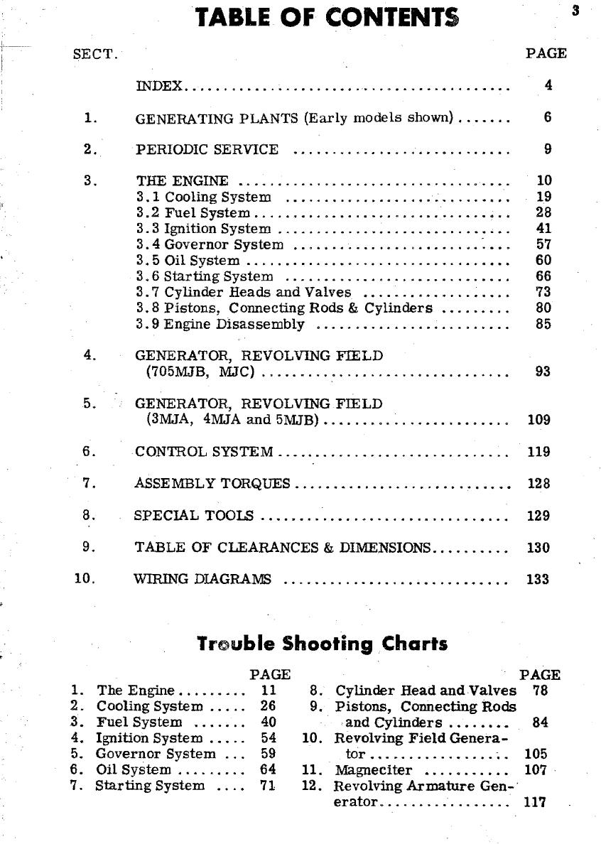
TABLE
OF
CONTENTS
SECT.
INDEX
.................................•........
1.
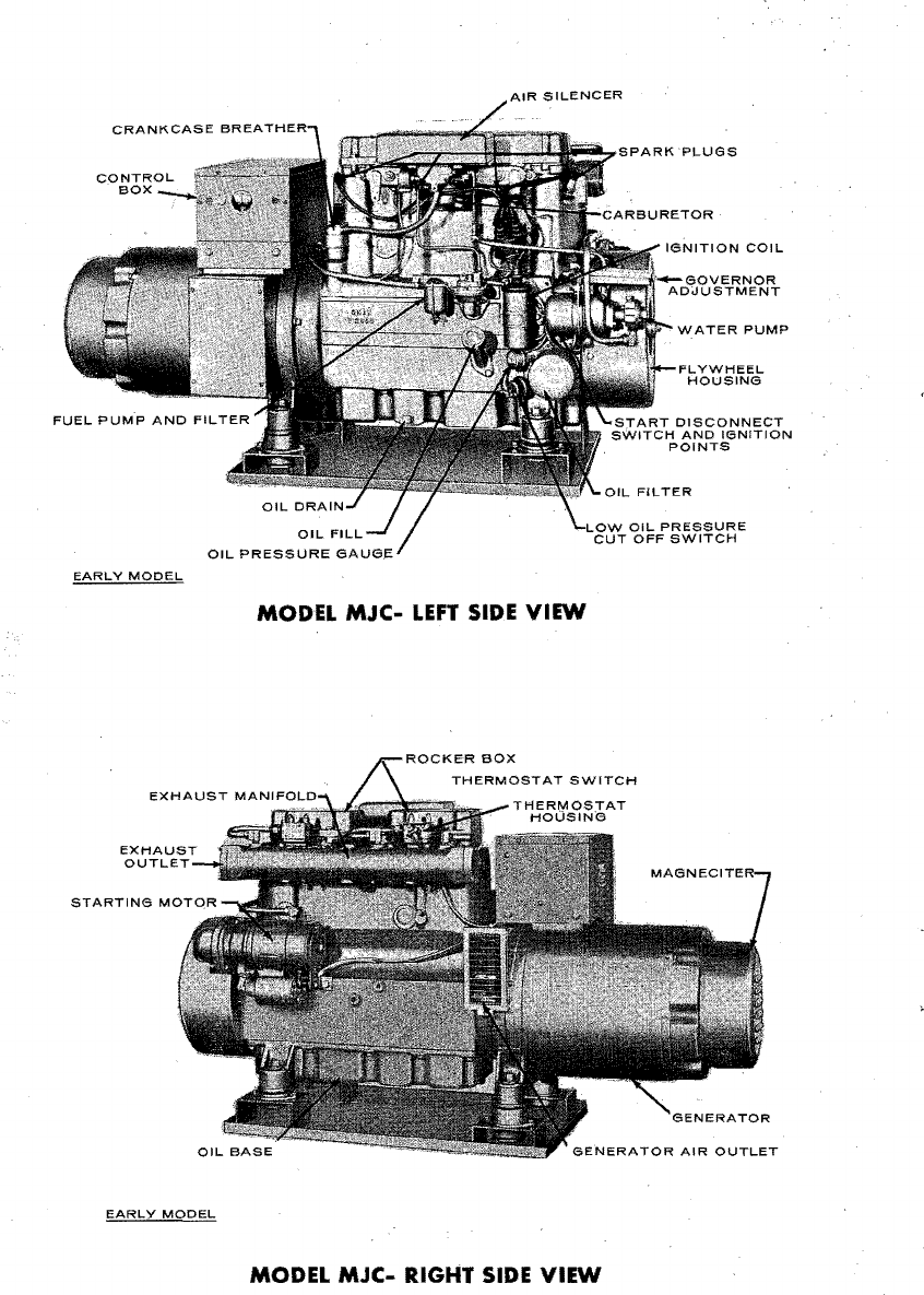
GENERATING PLANTS
(Early
models
shown)
.....
"
2.
PERIODIC SERVICE
...................•........
3. THE ENGINE
•................................•.
3.
1 Cooling
System
............................
.
3.2
Fuel
System
..............................•..
3.3
Ignition
System
...................•.......••.
3.4
Governor
System
........................
~
•..
3.
5
Oil
System
..............................•.••
3.
6
Starting
System
............................
.
3.7
Cylinder
Heads
and
Valves
••................•
3.8
Pistons,
Connecting
Rods
&
Cylinders
.•.......
3.9
Engine
Disassembly
........................
.
4. GENERATOR, REVOLVING
FIELD
(705MJB, MJC)
...............................
.
5. GENERATOR, REVOLVING
FIELD
(3MJA, 4MJA
and
5MJB)
•.......................
6. CONTROL SYSTEM
.............................
.
7. ASSEMBLY TORQUES
...........................
.
8.
SPECIAL
TOOLS
.............................•...
9. TABLE
OF
CLEARANCES & DIMENSIONS
.••......•
10.
~G
DIAGRA~
..................•..........
Trouble
Shooting
Charts
PAGE
1.
The
Engine.
. . . . . .
..
11
2.
Cooling
System
..
.
..
26
3.
Fuel
System
.......
40
4.
Ignition
System
...
. . 54
5.
Governor
System
...
59
6.
Oil
System
...
. . . .
..
64
7.
Starting
System
....
71
8.
9.
10.
11.
12.
Cylinder
Head
and
Valves
Pistons,
Connecting
Rods
and
Cylinders.
. . . ••
••
Revolving
Field
Genera-
tOr
••.........•....
~.
Magneciter
•...•......
Revolving
Armature
Gen-'
erator....
..
......
.....
PAGE
4
6
9
10
19
28
41
57
60
66
73
80
85
93
109
119
128
129
130
133
PAGE
78
84
105
107,
117