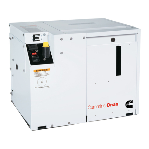
Onan GenSet NHL User manual

Operator's
@LISTED
Manual
'
6.3
kW
GenSet
LiquidLPG Fuel
RV
Electric GeneratingSet
940-0125
(SPEC
P)
1-83
Printed
In
U.SA

Redistribution or publication of this document,
by any means, is strictly prohibited.

Safety
Precautions
This symbol warns of immediate
hazards which will result in severe
This symbol refers to a hazard or
unsafe practice which can result in
This symbol refers to a hazard or
unsafe practice which can result in
personal injury or death.
severe personal injury or death.
personal injury or product or property damage.
Fuels,electricalequipment,batteries,exhaustgasesandmoving
partspresentpotentialhazardsthatcould resultinserious,per-
sonalinjury.Takecareinfollowingtheserecommendedprocedures.
Do not work on this equipment when mentally or physically
fatigued.
UseExtremeCautionNearFuel. A constant potentialexplosive
or fire hazardexists.
Donot
fill
fueltank near unitwith engine running. Donotsmoke
or useopen flame nearthe unit or the fueltank.
Besure all fuel supplies have a positiveshutoffvalve.
Usea non-metallic,non-conductive,flexiblesectionof fuel line
betweenthe generator setandstationaryfuel line invehicle.
LPG: The propane fuel supply lines MUST comply with all
requirementsofNFPA501CSection3-5,paragraphs1.1 and1.2
as well as Canadian Gas Association Bulletin B149.2-78. The
installer must review and comply with all applicable codes
regardingfueltanks,supplylines,andpressuretestingcomplete
systemfor leaksafterinstallationiscompleteandPRIORtoinitial
operationof the generator set.
Haveafire extinguishernearby. Besureextinguisherisproperly
maintained and be familiar with its proper use. Extinguishers
rated ABC by the NFPA are appropriate for all applications.
Consult the local fire departmentfor the correct type of extin-
guisherfor variousapplications.
I
GuardAgainst ElectricShock
Remove electric power before removing protective shields or
touching electrical equipment. Use rubber insulative mats
placed on dry wood platformsoverfloors thataremetalor con-
crete when around electrical equipment. Do not wear damp
clothing (particularly wet shoes) or allow skin surfaces to be
damp when handlingelectrical equipment.
Jewelryisagoodconductorofelectricityandshouldberemoved
when working on electrical equipment.
DO NOT CONNECT GENERATOR SET DIRECTLY TO ANY
BUILDINGELECTRICALSYSTEM. Hazardousvoltagescanflow
fromthegeneratorsetintotheutilityline.Thiscreatesapotential
for electrocution or propertydamage. Connect only through an
approveddeviceandafterbuilding mainswitchisopen. Consult
an electrician in regardto emergency poweruse.
Use extreme caution when working on electrical components.
Highvoltages cause injury
or
death.
Follow all state and local electrical codes. Have all electrical
installationsperformed by a qualifiedlicensedelectrician.
Do
NotSmokeWhile ServicingBatteries
Batteries emit a highly-explosive gas that can be ignited by
electricalarcing or bysmoking.
ExhaustGasesAre Toxic
Neversleep inthevehiclewiththegeneratorset running unless
the vehicle is equipped with an operating carbon monoxide
detector.
Provide an adequate exhaust system to properly expel dis-
charged gases. Check exhaust system-regulady-for leaks.
Ensurethat exhaust manifoldsare secure and notwarped.
Be surethe unit is well ventilated.
--
Keepthe UnitandSurrounding Area Clean
Removealloildeposits.Removeall unnecessarygreaseandoil
fromtheunit.Accumulatedgreaseandoilcancauseoverheating
andsubsequentenginedamageandmaypresenta potentialfire
hazard.
When cleaning generatorset, provide cover or other protection
so
thatcleaningandrinsewater, andothercontaminantsarenot
allowedintothegenerator,aircleaner,controlbox,fuelsolenoid,
or electrical connectors. Generator set operation and internal
componentscan be adverselyaffected.
Do
NOTcleanthe generatorset while unit isoperating.Thiscan
resultinpersonal injury or product or propertydamage.
Do
NOT use high pressure air, water,
or
steam for cleaning
generatorsetandcompartment.Dirtandotherforeignmattercan
beforced into generator,engineandcontrol housings.Genera-
tor set operation and internal components can be adversely
affected.
Do NOT usehighstrengthsolvents.They candamageelectrical
connectors.
DoNOTstoreanythinginthegenerator compartmentsuchas oil
orgas cans, oily rags, chains,woodenblocks,portablepropane
cylinders,etc.
A
fire could resultor the generator set operation
(cooling, noise and vibration) may be adversely affected. Keep
the compartmentfloor clean and dry.
ProtectAgainst MovingParts
Avoid movingparts of the unit. Loosejackets,shirts or sleeves
should not be permitted because of the danger of becoming
caught inmoving parts.
Makesureallnutsandboltsaresecure.Keeppowershieldsand
guards inposition.
If adjustments
must
be made while the unit is running, use
extremecaution around hot manifolds,moving parts, etc.
0
General
Do not work on this equipment when mentally or physically
fatigued,orafterconsumingany alcohol ordrug that makesthe
operation of equipment unsafe.
RV-G.LP-1
Redistribution or publication of this document,
by any means, is strictly prohibited.
Redistribution or publication of this document,
by any means, is strictly prohibited.

TO
THE
OWNER
Welcometothegrowing familyof
Onan
Powerusers.
.
-
We are proudto have you as a customer.
Read this manual carefully and observe all safety
ruleswithin. Operatinginstructions, adjustmentsand
periodic maintenance procedures are given
so
that
you.. .theowner,cankeepyourunitrunninglikenew
andexpect manyyears of dependable servicefromit.
Remember.
..
any machine, regardlessof design or
type, will perform only
in
relation to the services
it
received.
If
yourgenerator set needsspecialattention, ask your
Onan dealer for assistance; the Onan Parts and
Service Organization has been factory-trained to
provide up-to-date know-how for keeping your
RV
electric generating set “on the road”.
A
reader comment form is located next to the rear
cover. Your comments and questions about this
manual will help us produce a better publication in
the future. Please detach and fill out this card and
send back to Onan Corporation. Postageis prepaid.
TABLE
OF
CONTENTS
General Information
..........................
2
Specifications
.................................
3
Installation Checks
...........................
4
Operation
....................................
6
Engine Troubleshooting
......................
11
Maintenance
.................................
12
Assembly Torques..
..........................
14
Periodic Maintenance Schedule
...............
16
Adjustments..
................................
17
Control Troubleshooting..
....................
20
Remote Accessories
..........................
22
TO PREVENT FIRE
OR
ACCIDENT HAZARD.
..
THIS UNIT MUST BE INSTALLED ACCORDING
STALLATION PROCEDURES OBSERVING ALL
MINIMUM CLEARANCES.
TO AVOID POSSIBLE PERSONAL INJURY
OR
EQUIPMENT DAMAGE, ANY INSTALLATION
AND ALL SERVICE MUST BE PERFORMED BY
QUALIFIED PERSONNEL.
TO
THE MANUFACTURER’S DETAILED IN-
1
Redistribution or publication of this document,
by any means, is strictly prohibited.

General
Information
YOUR
MANUAL
This manual contains operation and other informa-
tion to properly maintain, service, and make adjust-
ments on your NHLgenerator set. Study and follow
theinstructionscarefully.
A
well-planned serviceand
maintenance program will result in longer unit life
andbetter performance. Becausethemost important
partof repair isdiagnosis, atroubleshooting chartis
included.
Throughoutthe manual, engine endof the generator
set is
the
front. Left and right sides are determined
when facing the engine (front) end.
COIL
EX
MA
When contacting your Onan dealer, distributor, or
thefactory about
the
generator set, alwayssupplythe
complete modelnumberandserial number asshown
on the nameplate (se
Model
Designation
following).
This information isnecessarytoidentifyyourgenera-
tor set among the many types manufactured by
Onan.
1
Onan electric sets are given acomplete runningtest
under various load conditions and are thoroughly
checked before leavingthe factory. Upon receiving
your unit, check it thoroughly for any damage that
may have occurred during shipping. Tighten loose
parts, replace missing parts and repair any damage
before operating the unit.
AIR
CLEANER
\
START-STOP
''
/
SWITCH
START-S
)c
DCFUS
LPG
FUEL
INLET
SPARK
PLUG
1
01
OILFILL
VIBRATION
ISOLATORS
(FAIL-SAFE)
LDRAIN
TOP
iES
TYPICAL
NHL
FOR
RECREATIONALVEHICLES
2
Redistribution or publication of this document,
by any means, is strictly prohibited.
Specifications
This manualcontainsSI metric equivalents that follow immediatelyin parentheses
after the
U.S.
customary units of measure.
GENERAL
Nominal Dimensions of Set
Height
.............................................................................
19.50
in.
(495
mm)
Width
..............................................................................
20.00
in.
(508
mm)
Length
.............................................................................
33.37
in.
(848
mm)
Weight
.............................................................................
305
Ibs.
(138
kg)
Manufacturer.
......................................................................................
Onan
Number of Cylinders..
..............................................................................
.TWO
Displacement (cubic inches)
.............................................................
.60
in3
(983
Cm3)
Cylinder Bore
............................................................
:.
.........
3-9/16
in.
(90.49
mm)
Piston Stroke..
..........................................................................
3
in.
(76.20
mm)
Compression Ratio
..............................................................................
.7.0
to
1
Engine Speed
..................................................................................
1800
rpm
Engine Design..
.........................................................
..Four Cycle, Air Cooled, L-Head
Horizontally Opposed
Starting System
.............................................................
Exciter Cranking (Generator)
.
Ignition
..........................................................................................
Battery
Recommended Fuel
.................................................
Propane (Commercial or HD-5 Grade)
Average Fuel Consumption
(at rated load
&
speed)
..................................................
1.70
Gallons per Hour
(6.44
L)
GENERATOR DETAILS
Manufacturer.
......................................................................................
Onan
Design
..........................................................
Revolving Armature, Four Pole,
1800
rpm
Rating (in watts
60
Hertz)
...................................................................
6,300(6.3
kW)
Voltage
...................................................................................
120
or
120/240
120
Volt..
...............................................................................
.52.5
Amperes
240
Volt
........................................................................
26.25
Ampereseach leg
Phase..
...........................................................................................
Single
Wire
...............................................................................
4
Wire Reconnectible
Output Rating
........................................................................
UnityPower Factor
.
Cranking Current..
..........................................................
;.
...
100
Amperes (Nominal)
Oil Capacity..
.....................................
3
US.
Quarts
(2.8
lit)
Plus
1/2
Quart for oil filter change
Recommended Battery..
...................................................
.I2
Volt
74
Amp/Hr
(266.40
kC)
Battery Charge Rate (Fixed).
...............................................................
1-1/2
Amperes
Ventilation Requirements (Total-No Restrictions).
.....................................
120
sq. in.
(774
cm')
Spark Plug Gap
.......................................................................
,020
in
(0.51
mm)
Breaker Point Gap (Cold Setting).
......................................................
.016
in.
(0.41
mm)
IgnitionTiming Reference (Cold Setting)
........................................................
20"
BTC
Valve Tappet Clearance
Intake..
.............................................................................
Exhaust..
...........................................................................
ENGINE DETAILS
.
Current Rating (amperes)
CAPACITIES AND REQUIREMENTS
TUNE-UP SPECIFICATIONS
.005
in.
(.I27
mm)
.013
in.
(0.330
mm)
3
Redistribution or publication of this document,
by any means, is strictly prohibited.
Installation
Checks
INSTALLATION
Nearlyall Onan electric generating setsare installed
by the motor home manufacturer. Although the
manufacturer must follow safety codes when instal-
ling, certain installation problems could arise after
the unit is installed and subjectedtovibration. There
are a few areas that you as the operator should be
concerned with. If indoubtabout any aspect of your
generator set's operation or safety, contact your
nearest authorized Onan Service Center. A daily
inspection of your installation should include the
following:
EXHAUST
Check for leaks around manifolds, gaskets, and
welds. Make sure exhaust lines are not heating sur-
rounding areas excessively. If
so,
have corrected
immediately. Remember EXHAUST GASES CON-
TAIN DEADLY CARBON MONOXIDE. Be sure all
holes to the inside of
RV
from set compartment are
sealed to prevent poisonous exhaust gases from
entering vehicles.
All
exhaustshieldingsuppliedwithgenerator
set MUST be properly installed to prevent
overheatingof compartmentwalls or the possibliityof fire.
1.
2.
3.
19.50"
Do not terminate exhaust under vehicle, as
carbon monoxide gas
is
poisonous. Direct
exhaustgasesaway from window and door openings.
LIQUID PROPANEFUEL SYSTEM
Leaking propane will cause fumes
i
which could EXPLODE. Check
aroundall fuelsystem componentsand fuellinecon-
nectlons for loose or leakingjoints. Make sure fuel
lines are not rubbing against anything which could
causethem
to
break.Ifatall connectionsare
OK
ina
"staticcondition",recheck alljointsand Connections
usinga soap and water mixture withset running.
ELECTRICAL
AC
Output:
All
AC leads (MI,M2,
M3
and M4) termi-
nate in generator sets junction box. These wires
should beconnectedtodistributionbox with multis-
trand wire enclosed in a flexible conduit. Check all
wires (toandfromthe generator set) for fraying and
looseconnections. For information on load connec-
tions referto operation section following.
Battery Connections:
Batterypositive
(+)
connection
connectstostartsolenoid. Batterynegativeconnects
to location on rear of generator. Check terminals on
set and battery for clean and tight connections.
.-
r---
33*37"
1/2
MIN CLEARANCE TO TOP
7
-I
'I
I
I
I
I
I
I
I
I
1"
I
CLEARANCE
I
I
112
DRAIN HOLES IN ALL
-
FOUR CORNERS
MINIMUM
CLEARANCE
\
\
\
t
\
\
DRIPPAN
MINIMUM SCROLL COMPARTMENT OIL DRAIN
OUTLET DIAMETER FLOOR CLEARANCE
9.69
x
4.00" 1-112"
DIMENSIONSIN
(
)
ARE MILLIMETERS
4.
VACU-FLO SCROLLEXTENDS BELOW MOUNTING PLATE
APPROXWEIGHT
305
LBS
Al.OO"(25)
MINCLEARANCEREQUIREDAROUNDSETAND
50
(13)
MINABOVECARBTO COMPARTMENTWALLS
OR
SOUND
INSULATION (OIL FILTER MAY PROTRUDE INTO
1.00'' (25)
CLEARANCE).
MASS
138
kg
5.
FOR CUSTOMERSCOMPARTMENTHOLE
SIZE
FOR SCROLL:
51
WIDTH:
4.00
(102)
5.2
LENGTH:
9.69
(246)
FIGURE
1.
INSTALLATIONOUTLINE
4
Redistribution or publication of this document,
by any means, is strictly prohibited.

Onan recommends using a separate battery
for
operation
of
the
generator set
in
addition to the regular vehicle starting battery.
Refertoindividualinstaliationguideforadditionalinformationon
batterysharing.
Grounding:
Generator must be effectively bondedto
recreational vehicle chassis.
VENT1
LATl
ON
The biggest enemy of electric generating sets in-
stalled
in
motor homes
is
excessiveheat. Makesure
theset's air inletandoutlet are notpluggedwithdust,
dirt, bugs, leaves
or
anything that could restrict
cooling
air.
WAR^^^^
Don't usedischargedcooling airforcompart-
7)
ment heating since it could contain
poisonous exhaust gases.
For
additional information on installation contact
your Onan Service Representativeor request Instal-
lation Guide
#940-0625.
wARNING
Do not terminate exhaust under vehicle, as
71
carbon monoxide gas is poisonous. Direct
exhaust gases away from window and door openings.
Vehicle chassis (frame) groundand the battery and generator set
ground should
all
be electrically connected
to
be at
0
ground
potentlal. All Onan units are designed for negative around
-
-
-
apollcatlon. On
all
listed models with exhaust shielding
j-1
supplied with unit, shielding MUST be
properly installed toprevent overheating
of
Compartment walls or
the possibility of fire. Refer to appropriate installation guide for
each model for details.
Mountthe battery in
a
separatecompartment
fromtheset orany spark-producingdevice
to
preventfire or explosion.
Do not smokewhile servicing batteries. Lead
acid batteries give
off
explosive gaseswhile
being charged.
DO NOT DISCONNECT BATTERY CABLES
FROM
BATTERY
WHILE
GENERATOR SET
ISCRANKING
OR
RUNNING;SPARKS MAY CAUSEAN EXPLO-
SION.
IMPORTANT
Certainstates(particulariyCalifornia) havestate
ordinances pertaining to the type and usage
of
exhaust
muffler/spark arrestersoninternal combustlon engines orengine
driven equipment when used in a recreational vehicle such as
electric generating sets. Besureyourinstallationmeets
all
Federal,
Stateandlocalcodespertainingtoyourunit. Failuretoprovideand
maintain a spark arrester may be
in
violation
of
the law.
I
WARNING^
EXHAUST
GAS
IS
DEADLY!
Exhaustgases containcarbonmonoxide,anodorlessandcolorlessgas. Carbon
monoxideispoisonousandcancauseunconsciousnessanddeath.Symptoms
of
carbonmonoxidepoisoning can include:
Dizziness
Nausea Muscular Twitching
Headache
e
Vomiting
Weaknessand Sleepiness
Throbbingin Temples
e
Inability to ThinkCoherently
IF
YOU
OR
ANYONE ELSE EXPERIENCEANY OF THESESYMPTOMS, GET OUT
INTO THEFRESH
AIR
IMMEDIATELY.
If
symptomspersist, seekmedical atten-
tion. Shut down the unit and
do
not operate until it has been inspected and
repaired.
Neversleepinvehiclewiththegeneratorsetrunningunlessthevehicleinterioris
equippedwithanoperatingcarbonmonoxidedetector.Protectionagainstcarbon
monoxideinhalationalsoincludesproper exhaustsysteminstallation and visual
and audible inspection
of
the complete exhaust system at the start
of
each
generatorset operation.
5
Redistribution or publication of this document,
by any means, is strictly prohibited.
Operation
BEFORE STARTING
Inspection:
Inspect the engine visually before star-
ting. Check for looseormissing partsoranyshipping
damage.
CRANKCASE
OIL
The set oil capacity is 3 US.quarts
(2.8
lit) plus
1/2
quart for oil filter change. Fill the crankcase untilthe
oil reachesthe “FULL” mark on theoil levelindicator
(Figure
2).
Do
NOT OVERFILL. (Overfilling may
cause foaming and engine shutdown.) Always
change the oil filter when changing oil. Refer to
Periodic Maintenance Schedule
in
MAINTENANCE
section for service interval.
CAP AND OIL
LEVEL INDICATOR
OIL
LEVEL
-
ALWAYSREPLACE
CAP TIGHTLY,
OR
OIL LEAKAGE MAY
OCCUR.
KEEP OIL
AT THIS LEVEL
-
-
---
-
NEVER OPERATE
-
-
-
-
-
ENGINEWITH OIL
BELOW THIS LEVEL
U
FIGURE
2.
CHECKING
OIL
LEVEL
Be sure to fill the crankcase with oil to the “FULL”
mark on the oil level indicator. Use oil with the API
(American Petroleum Institute) designation
SE
or
SE/CC. Oil should be labeled as having passed
MS
Sequence Tests (also known as having passed
ASTMG-1V Sequence Tests). Refer to oil chart for
recommended viscosity and temperature.
Oil consumption may behigher with amultigrade oil
than with a single grade oil if both oils have com-
parable viscosities at
210”
F
(99
“C). Therefore,
single gradeoils aregenerally moredesirable, unless
anticipating a wide range of temperatures.
Useof thesamegradeandqualityofoilasthat usedin
your recreationalvehicleengineisacceptableas long
as unit is serviced regularly and oil meets re-
quirements shown
in
chart.
Do NOT check
oil
while the generator set
is
operating.
Hot
oil could cause burns by
blowing
out
of
oil
fill
tube due to crankcase pressure.
EFORE
NEXT
OIL
CHANGE
Check oil leveldaily and change oil every
100
normal
operating hours. SeeFigure3forlocationof oildrain.
Ifoperating inextremely dustyordirtyconditions,the
oil might haveto bechangedsooner. Whenaddingoil
between changes, use the same brand as in the
crankcase. Various brands of oil might not be com-
patible when mixed.
-
--
FIGURE
3.
OIL
DRAIN
AND
FILL
LIQUIDPROPANE GAS FUEL
RECOMMENDATIONS
Useclean, fresh commercial propaneor
HD-5
grade
liquid propane gas ina mixture of at least
90%
pro-
paneorgreater. Propanefuelsotherthan
HD-5
grade
maycontain morethan
2.5%
butane. Use
of
propane
fuel mixtures containing more than
2.5%
butane will
result
in
poorfuelvaporization andenginestartingin
low ambient temperatures. Liquid propane gas that
has not been properly stored and transported may
containa large portionof contaminates. Always pur-
chase propanefrom a reputable dealer.
6
Redistribution or publication of this document,
by any means, is strictly prohibited.
LP gas, propane and butane are extremely
ffammable substances which
MUST
be
handled
withextremecare.DoNOToperate
thegeneratorsetinan
enclosedarea.
Do
NOTsmoke.
Ail
bulk tank@)
are
pressurized
but
require vaporization
to
operate appliances
or
use as a vehicle
enginefuel source. Keep
a
typeABC
fire
extinguisherhandy.
Leakage
of
propane in
or
around the com-
partment
is
a
definite hazard. The system
shouldprovide aconstantflow
of
airtoexpel anyaccumulation
of
fuel vapor while the vehicle
is
in transit. Compartments must be
vapor tight tothe interior
to
keepfumes
from
within thevehicle.
START1
N
G
Push the start-stop switch to the start position.
Releasetheswitch when engine starts. Ifenginefails
to start, inhibitor oil used at the factory may have
fouled thespark plugs. Removetheplugs, clean ina
suitablesolvent, drythoroughlyandre-install. Heavy
exhaust smoke when the engine is first started is
normal and caused bythe inhibitoroil.
STOPPl
N
G
Push the start-stop switch to the stop position and
hold until unitstops completely.
BREAK-IN PROCEDURE
Controlled break-in with the proper oil and a con-
scientiously applied maintenance program will help
toassuresatisfactory servicefromyour Onanelectric
generating set. Break-in as follows:
1. One half hour at 1/2 load (with one air condi-
tioner) and approximately
500
watts additional
load.
2. One half hour at 3/4 load (with one air condi-
tioner) and approximately 1500-2000watts addi-
tional load.
3. Change crankcase oil after the first
50
hours of
operation.
APPLYING LOAD
If practical,allow settowarm upbeforeconnecting a
heavy load. Continuous generator overloading may
cause highoperating temperatures that can damage
thewindings. Keeptheloadwithin nameplate rating.
LOAD CONNECTIONS
1.
Generator set load wires (Ml, M2, M3 and M4)
terminate ingenerator sets's junction box. Con-
nect and join wires within junction box in an
approved manner for desired voltage code. See
Figure4.
2. Wires must be adequate size, properly insulated
and supported.
3. Mountswitches andcontrolssecurely to prevent
damage from vibration and road shocks. All
switches must be vibration proof to prevent
accidentalopening orclosingwhilethevehicle is
in motion.
4.
All wiring must meet applicable local electrical
codes. Have a qualified electrician install and
inspectthewiring.
EXERCISE
Infrequent
use
results in hard starting. Operate
tm
generator set one30-minute period each
v*;.tek.
Run
longerif batteryneeds charging. Exercising for one
long period each week
is
better than several short
periods.
BATTERY CHARGING
Thebatterycharge rateiscontrolled byafixed value
resistor that allows a tricklecharge rate of
1
-
1-1/2
amps under all conditions.
HIGHOPERATING TEMPERATURES
1.
See that nothing obstructs air flow to and from
the set.
2.
Keep cooling fins clean. Air housing should be
properly installed and undamaged.
3. Keep ignitiontiming properly adjusted.
LOW OPERATINGTEMPERATURES
1.
Use correct SAE oil for temperature conditions.
Changeoilonlywhen engine iswarm. Ifan unex-
pected temperature drop causes an emergency,
movevehicle to awarm location.
2. Useof commercial propane or HD-5 grade liquid
propane gas ina mixture of at least
9O0%
propane
orgreaterwillpermitreliablegenerator set opera-
tion downto
-1OOF
(-24OC). Propanefuels other
than commercial or HD-5 grade may contain
more than
2.5%
butane resulting in poor fuel
vaporizationandenginestartingincolderambient
temperatures.
3. Keep ignition system clean, properly adjusted
and batteries ina well charged condition.
4. Partially restrict cool airflow, but use care to
avoid overheating.
A carburetorair preheater kit
is
available
for
coldweather opera-
tion -below
45"
F
(7OC),
which helps prevent carburetor icing.
OrderKit
No.
140-1673.
EXTREMELY DUSTY
OR
DIRTY
1.
Keep unit clean. Keep cooling surfaces clean.
2. Service air cleaner as frequently as necessary.
3. Change crankcase oil every
50
operating hours.
4. Keep oil and gasoline in dust-tight containers.
5.
Keepgovernor linkage clean.
6.
Cleangenerator brushes, slip rings,andcommu-
tator, do
not
remove normaldark brownfilm. Do
not
polish.
HIGHALTITUDE OPERATION
Foroperation at altitudes of2500 feet
(775
m) above
sea level, close carburetor main jet adjustment
slightly to maintain proper air-to-fuel ratio (refer to
the
ADJUSTMENTS
section). Maximum power will
bereducedapproximatelyfourpercentforeach1000
feet
(310
m) above sea level after thefirst 1000feet.
Redistribution or publication of this document,
by any means, is strictly prohibited.
G
E
NL
EE
RA
AD
TS
0
R
G
E
NL
EE
RA
AD
TS
0
R
POWER REQUIREMENTS
FOR
APPLIANCES
Appliance or Approximate
Tool
Running Wattage
Refrigerator..
........................
.;
600-1000
Electric broom
..........................
200-500
Coffee percolator.
.......................
550-700
Electric frying pan
....................
1000-1350
Hair dryer..
.............................
350-500
Electric stove (per element)
.............
350-1000
Electric iron..
..........................
500-1200
Radio
....................................
50-200
Electric water heater..
................
1000-1500
Space heater
.........................
1000-1500
Electric blanket..
.........................
50-200
Television
...............................
200-600
Electric d
ril
I
.............................
250-750
Battery charger..
......................
Up to
800
Electric water pump
.....................
500-600
Air Conditioner..
......................
.1400-2200
Converter
...............................
300-350
Microwave oven
........................
.700-1500
JOIN BOTH BLACK LEADS
HERE
FOR
FULL RATING
SINGLE CIRCUIT
120
VOLT
CB2
::
fz
BLACK
+
'17
UNGROUNDEDLOAD WIRE
0
t
120
v
TO
VEHICLE
BLACK
1
LOAD
120
v
I
M2
a
M4
GROUNDED LOAD WIRE
1-
WHITE
-
L
1
120
VOLT LOAD
WIRE CONNECTIONS
CBl
Ml
n
BLACK UNGROUNDED LOADWIRE
-
t
1
M2
130
v
1,
-
WHITE
.c
I
240
V
GROUNDED LOADWIRE
4
I
-
Y3
CB2
120v
I
I
t t
BLACK UNGROUNDED LOADWIRE
120/240
LOAD
WIRE
CONNECTIONS
TO
VEHICLE
LOAD
FIGURE
4.
SINGLE-PHASE,
"-3C"
VOLTAGE CODE GENERATOR CONNECTIONS
8
Redistribution or publication of this document,
by any means, is strictly prohibited.
Current fed to
generator series field,
cranks engine.
I
Operate startswitch untilgenerator speed buildsup.
Battery current fed to
ignitioncoil and LPG
fuel solenoid valve
Generator supplies current to
ignition, coil and LPGfuel
solenoid valve Recharges battery.
-
-
FIGURE
5.
SEQUENCE
OF
OPERATION
SEQUENCE
OF
OPERATION
Figure
5
shows the operation sequence of the NHL
electric generating set. Figure
6
shows the flow dia-
gram for the
LPG
liquid
fuel system components
used on this
RV
generating set.
9
Redistribution or publication of this document,
by any means, is strictly prohibited.
CARBURETOR
Venturitypewith botha"Main" and "Idle"
jet
adjustments.
I
REGULATOR
Two
stagedesignthat will ONLY flow fuel
when carburetor provides suction
to
fuel outlet.
SOLENOIDVALVE
A "Normally Closed" valvewhich allows fuel
flow ONLY when engine iscranking or running.
This valve also back flows to prevent hydrostatic
pressure build up invaporizer and regulator.
FUELFILTER
Changes propane fu
generatorset.
Protectsengine and fuel systemcomponents
from contaminates. An internal magnetstops all
magnetic particlesthat may collect on fuel lock
solenoid plungerand foul
its
action or plug
fuel filter.
CustomerSuppliedand Installed Hardware
CustomerMust Satisfy UL1248 NFPA
58.
CSA946.
CAN1-B149.2-78 and Any LocalCodes That Apply.
\
PRESSURERELIEFVALVE
Locate invapor space internal
to
fueltank. (Relief pressure
between274 and 375 PSI depending
ontank specified and expected
ambient).
HYDROSTATICRELIEFVALVE
Must be located after manual shutoff
valve. Relief pressure between
400 and
500
PSlG MUST be properly
vented.
MANUALSHUTOFFVALVE
Must
Be MountedonTank
X
Pipings,
Hoses
and Fittings
Must beApproved For LPG Fuel
FUELTANK
(Generator Set
and Other Vehicle ADDkmCeSl System Use.
\
INTERNALEXCESS
FLOW
VALVE
Must conformto ASME or docand
CTC standards. (Working pressure
between
240
and 375 psi depending
ontank selected). For Limitations,
Must Close with Complete Line
Breakage. Consult National LP Gas
Association Publication113-78
FS-1465
FIGURE
6.
FLOW DIAGRAMOFLPG"LIQUID" FUELSYSTEMCOMPONENTS
10
Redistribution or publication of this document,
by any means, is strictly prohibited.

EngineTroubleshooting
I
I
1
I
I
I
1
1-1
l~l..~l,,,~,l,,,,l,
I
~~
Faulty Spark PlugWires
FUEL SYSTEM
I
II
I I
.pI
1
1
Poor Air C
i
rcula
ti
on
I
I0I.I
1
I
I
Dirty or Oily Cooling
Fins
I
LL
I
INTERNAL ENGINE
I
.I
1.1
1-
Wrong Bearing Clearance
COOLING SYSTEM (AIR COOLED)
.-. .
~!
11
Redistribution or publication of this document,
by any means, is strictly prohibited.
Maintenance
BATTERYCARE
To increase battery life, the operator can perform a
number of routine checks and some preventive
maintenance.
1.
2.
3.
4.
5.
6.
Keepthe battery case clean and dry.
Make sure the battery cable connections are
clean and tight. Use a terminal puller when re-
moving cables for any reason.
Coat the battery terminals with a mineral grease
or petroleum jelly to reduce corrosion and
oxidation.
Identifyeachbatterycabletobepositiveor nega-
tive before making any connection. Always con-
nect theground (negative) cable last.
Maintain the electrolyte level of adding water
(drinkingqualityorbetter)as neededforfillingto
split level marker. (The water ingredient of the
electrolyte evaporates, but the sulphuric acid
ingredient remains. Therefore, add water, not
electrolyte.
Avoid overcharging when recharging. Stop the
boost charge when the specific gravity is 1.260
and the electrolyte is
80"
F (26.7"C).
LPGFUELFILTERAND SOLENOIDVALVE
Onan liquid LPG generator sets contain afilter car-
tridge and magnet within the fuel solenoid valve to
protect the solenoid valve and regulator valves from
dirtand metallicparticles. LPGfuel that hasnotbeen
properly stored andtransported maycontain a large
portion of contaminates. Always purchase propane
from a reputable dealer. If the fuel filter becomes
plugged,the generator setwilloperate erractically at
heavier loads and/or in colder weather due to high
fuel demand and lower tank pressure to push liquid
propane through the filter inthe fuel solenoid valve.
Fuelsolenoid valve and filter is shown in Figure 7.
COOLING SYSTEM
The generator set iscooled byaflywheel blower fan
which pulls air over the cylinders and cooling fins.
The air path
is
directed by sheet metal shrouds and
plates. These shrouds and plates must always be
installed properly
so
unitdoes not overheat.
Check and clean (if necessary) the cooling fins at
leastevery
200
hoursof operation. Removeany dust,
dirtoroilwhich mayhaveaccumulated. Check com-
partmentair inletandgeneratorsetairoutletforbuild-
up of dirt, chaff, etc.
SOLENOID
COVER
w-
RETAINER
&-
O-RING
e-,
MAGNET
RETAINER
l$-
SPRING
BASE,BOWL
@
FIGURE
7.
FUELSOLENOIDVALVE AND FILTER
AIR
CLEANER ELEMENT
Check and clean element at least every 100 hours.
Loosen wing nut to remove. Clean by tapping base
lightly on a flat surface. Replace element at least
every
200
operating hours; clean or replace more
often industy conditions. See Figure
8.
FIGURE
8.
AIR CLEANER ELEMENT
12
Redistribution or publication of this document,
by any means, is strictly prohibited.

SPARK PLUGS
Replacespark plugsevery
100
hoursorat leastonce
a
year. A badlyleaded plugwillcausemisfiring, poor
operation orstopping when a load is applied.
Badlyorfrequentlyfouledplugindicatestheneed
for a majortune-up.
Each time the spark plugs are removed, inspect,
clean and regap (Figure
9).
If the plug looks dis-
colored or hasfouled, replace it.
A873
FIGURE
9.
CHECKING SPARK PLUG GAP
GOVERNOR LINKAGE
The linkage must be able to move freely through its
entire travel. Every
50
hours of operation, clean the
joints and lubricate as shown in Figure
10.
Also
inspect the linkage for binding,excessive slack and
wear.
TO LOOSEN, PULL KEEP GOVERNOR
JOINT APART, CLEAN LINKAGE LUBRICATED
AND LUBRICATE WITH WITH GRAPHITE
GRAPHITE
FIGURE
10.
GOVERNORLINKAGE
0
UT-
0
F-S
E
RV
I
CE PROTECTI
0
N
Protect a generator set that will beout of service for
more than
30
days from damage caused by rust or
corrosion. Use the following procedure to properly
protectthe set.
1.
Run the generator set with at least a
50%
load
until thoroughlywarm (usually about
1
hour).
2.
3.
4.
5.
6.
7.
8.
9.
10.
Close the manual shut-off valve on the vehicIe
propanesupplytank andallowthegeneratoiset
to
run
out of fuel andstop.
Drain the oil from oil base while engine is still
warm. Replace the oil filter if
so
equipped.
Replace drain plug and refill. Attach a warning
tag stating type and viscosity of oil used.
Removespark plugs. Pour
1
ounce of rust inhibi-
tor oil (or SAE
#IO)
into each cylinder. (Spray
canswork well for this application). Turnengine
over by hand at least
2
complete revolutions.
Replacethe spark plugs.
Replace the air cleaner at least on an annual
basis.
Plug the exhaust outlet to prevent entrance of
moisture, dirt, bugs, etc.
Clean and oil all exposed engine parts including
carburetor and governor linkage.
Wipe generator brushes, slip rings, housing,etc.
.
Do
notapply any lubricant or preservative.
Removethe battery and store inacooldryplace.
Coatthebatteryterminalsandcableconnections
withvasoline orgreaseto prevent any corrosion.
Rechargethebatteryatleastmonthlyormaintain
with a trickle type battery charger.
Provide a suitable cover if the unit isexposed to
the elements.
RETURNING THE UNIT
TO
SERVICE
1.
Remove the cover and all protective wrapping.
Wipe the oil film off all exposed engine parts.
Removethe plugfrom the exhaust outlet.
2.
Visually inspect the unit for any damage. Check
to be sure the carburetor and governor linkage
arefree. Removethegeneratorendbellbandand
check to besure the brushes work freely intheir
holders.
3.
Check the tag to ensure oil of the proper brand
andgrade has been installed. Check theoil level.
4.
Install the battery (be sure battery is fully
charged), observing proper polarity. Ground is
negative.
5.
Remove spark plugs, clean and gap. Turn the
engine over by hand several times. Reinstall
spark plugs.
6.
Open the manual shut-off valve on the vehicle
propane supply tank.
7.
Removeall loadandstart thegenerator set atthe
unit. Initial start may be slow due to oil or rust
inhibitor inthe cylinders. Excessive smoke and
rough operation will occur until the oil or rust
inhibitor is burned off.
8.
Apply a
50%
loadaftertheset runssmooth. Allow
the generator set to warm up
(1
hour) with the
load connected. Check speed and voltage.
9.
Unit is now ready for service.
13
Redistribution or publication of this document,
by any means, is strictly prohibited.

GENERATOR MAINTENANCE
The generator normally needs littlecareother than a
periodic check of the brushes, commutator and
collector rings. If a major repair job onthegenerator
should become necessary, have the equipment
checked by acompetent electrician who isthorough-
ly familiar with the operation of electric generator
equipment.
Brush
Replacement
Installnewbrusheswhentheoldonesareworn tothe
dimensions shown in Figure11. Removethe end bell
bandtoexpose the brushholders. Removethe three
screws holding each brush holder
in
place (Figure
11).Removetheoldbrushesandcleantheholders
so
the new brushes can move easily in their holders.
Installthe newbrushesinthesame manneras theold
ones. Always use the correct brush as listed in the
PARTS CATALOG. Never substitute a brush which
may appear to bethe same for it may havedifferent
characteristics, New brushes are shaped to fit and
seldom needsandingtoseat properly. If some brush
sparking occurs after replacing brushes, run the set
under a light load until the brushes wear to a good
seat.
Collector rings acquire a glossy brown finish in
normaloperation.
Do
notattempt to maintainabright
newly machined appearing surface. Ordinary clean-
ingwith a dry, lintfree cloth isusually sufficient.Very
fine sandpaper (#200) may be used to removeslight
roughness.
ASSEMBLY TORQUES
Gearcase Cover.
............................
8-1
0
Rear Bearing PlateScrews..
................
25-28
Connecting Rod Bolt..
.....................
14-16
Flywheel Cap Screw
.......................
35-40
Other 5/16” Cylinder Block
Stud and Nuts
............................
8-10
Oil Base Mounting Screws..
................
18-23
Manifold Mounting Screws
.................
18-23
Oil Pump
.....................
:...............7-9
Exhaust Manifold
..........................
18-23
CYLINDER HEAD STUD NUT
TORQUE PROCEDURE
This generator set engine uses
a
special “graph-oil’’
head gasket and two compression washers and a
hardened flat washer on each
of
the top 6 longer
cylinder head studs as shown in Figure 12. The bot-
tom 4 shorter cylinder head studs use ONLY a har-
dened flat washer and NO compression washers as
shown in Figure 12. The final torque value varies
depending on whether compression washers are
usedor not.
Follow
thecylinder headtorquetighteningsequence
shown
in
Figure12. Start out tightening all nutsto
5
Ib.ft.
(7
Nom), then
10
Ib.
ft. (14 Nom), etc., untilthe
correcttorque isreached.Thetopsix nutsshould be
tightenedto12Ib.ft. (Nom) andthebottom four nuts
should betightened
to
15Ib. ft. (20 Nom).
BOLT TORQUE FT.-LB.
MEASURE FROM
TOP
FACE
OF
BRUSH
BLOCK
TO
TOP
OF
BRUSH
11/16”
I
I
REPLACE
I
1“
I
1
1/16”
I
FIGURE
11.
BRUSH
LENGTH
14
Redistribution or publication of this document,
by any means, is strictly prohibited.
Afterthecylinderheadstudnutshavebeentightened
once,
it
will be necessary to tighten each cylinder
head nuttothe specified torquea second time.
Fol-
lowthesamesequenceshown
in
Figurel2.Failureto
retorquecould result
in
ablown head gasket.
If
graph-oil gasket is removed at a
later date, the gasket surface must
be below
100°F
before removal. At temperatures
above
100"
F,
the gasket will become gummy and
difficultto remove from thesurfaceof theblock and
cylinder head.
LEFTCYLINDER
RIGHT
CYLINDER
NUMBERS INDICATECORRECT
TIGHTENING SEQUENCE FOR
CYLINDER HEAD NUTS
TORQUENUTSINPROPER SEQUENCE
TO SPECIFIED TORQUEVALUES LISTED,
TWICE BEFORERUNNINGTHEGENERATORSET.
EXHAUST
SPARK
ARRESTEWMUFFLER
Exhaust spark arresters are necessary for SAFE
OPERATION.Allrequireperiodicclean-out (every50
to 100 operating hours) to maintain maximum effi-
ciency. Some state andfederal parks requirethem.
To
clean spark arrester remove
1/8"
pipe plug
in
bottomof muffler. Run set under loadfor
5
minutes.
Replace plug. Inspect exhaust system (visually and
audibly) for leaks daily (at least every
8
hours of
runningtime).
Do NOT
operate generator set
if
-
exhaust system is damaged or
excessively noisy. Have
if
inspected and repaired
immediately by anauthorized Onanservicecenter.
COMPRESSION HEATTREATED NUTS
ARDENED WASHERS
-
HEAD GASKET
4
SHORT STUDS (BOTTOM)
6 LONGSTUDS (TOP)
TORQUETOP
SIX
NUTS
TO
12
LB.
FT.
(COLD) TORQUE BOTTOM FOUR
NUTSTO
15
LB. FT.
FIGURE
12.
CYLINDER
HEAD
STUD
NUT
TORQUESEOUENCE
'
c
15
Redistribution or publication of this document,
by any means, is strictly prohibited.
Periodic Maintenance Schedule
SERVICE THESE ITEMS
Regularly scheduled maintenance isthekey to lower the condition of the crankcase oil, the filters, etc.
operating costs and longer service
life
for the unit. frequently untilthe properservicetime periodscan be
The following schedule can be used as a guide. established.
However, actual operating conditions under which a
unit is run should be the determining factor in For any abnormalities in operation, unusual noises
establishing a maintenance schedule. When from engine or accessories,
loss
of power,
operating in very dusty or dirty conditions, Some of overheating, etc., contact your nearest authorized
the service periods may have to be reduced. Check Onan dealer.
8
50
100
200
400
Always allow generator set to
cool
EiEJ
off before performing any mainte-
nance or installation work on the set, Working on a
hot set could cause severe burns.
General Inspection
Check Oil Level
AFTER EACH CYCLE
OF
INDICATED
HOURS
x1
X
Change Crankcase Oil
Check Air Cleaner
Check Spark Plugs
x2
x2
x4
Check Breaker Points
Change Oil Filter
Clean Cooling Fins
x3
x2
x2
Replace Breaker Points
Clean Crankcase Breather
Replace Air Cleaner
x4
x2
x2
.
Check Generator Brushes (Reolace if Necessarv) As Reauired
I
~~
~~ ~~
'*
X1
-
With set running,visually and audibly check exhaust sytem
for
leaks
X2
-
Perform more often in extremely dusty conditions
X3
-
Replace
if
necessary
X4
-
Replaceannually or priorto storage
WARNING
All
exhaust system connections
MUST
be checked regularly for any leaksand
i
tightenedasnecessary.
Do
NOT
terminateexhaustpipeundervehicleor nearany
window or door openings. Inspectthe vapor tight sealsaroundallopeningsmade inthe set's
compartmentfor wiring, conduit, etc.,
to
prevententrance
of
any noxiousfumes
to
motorhome
interior.
16
Redistribution or publication of this document,
by any means, is strictly prohibited.
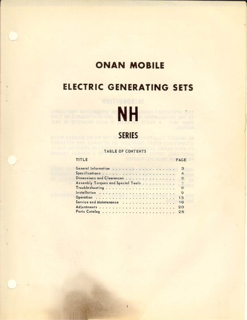
Table of contents
Other Onan Portable Generator manuals

Onan
Onan MEP-003A User manual

Onan
Onan KVC Series User manual

Onan
Onan DYH Series Instruction Manual

Onan
Onan MCCK Instruction Manual

Onan
Onan NH User manual

Onan
Onan MDKBH Series User manual

Onan
Onan DJB User manual

Onan
Onan LK Series Instruction Manual

Onan
Onan BF Series User manual

Onan
Onan Protec Series User manual
Popular Portable Generator manuals by other brands

Champion Global Power Equipment
Champion Global Power Equipment 201181 quick start guide

Porter-Cable
Porter-Cable BSI525 instruction manual

Rohde & Schwarz
Rohde & Schwarz SMBV100B quick start guide

Generac Power Systems
Generac Power Systems GP Series owner's manual

Briggs & Stratton
Briggs & Stratton 6344 installation instructions

Westinghouse
Westinghouse iGen2550c user manual